


Components
Tools, APP Software Used etc.
|
|
embedded C |
Description
Digital Wall Clock on PCB using AVR Microcontroller Atmega16 and DS3231 RTC
Project Overview
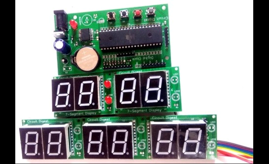
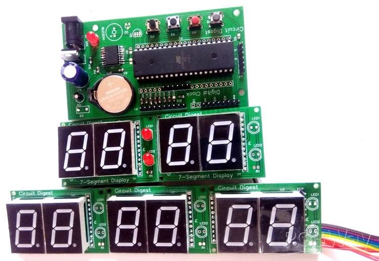
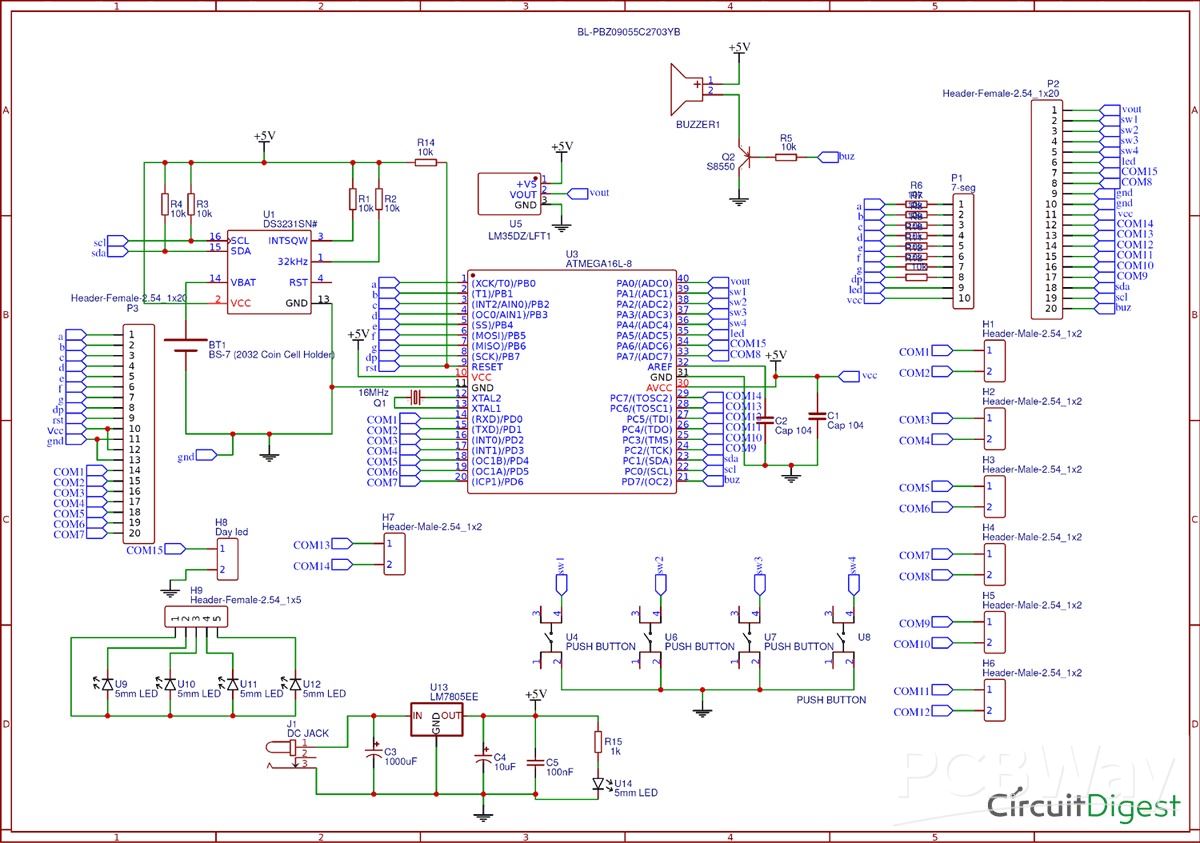
This digital wall clock project is a modular, PCB-based timekeeping system using an ATmega16 microcontroller and a DS3231 real-time clock (RTC) IC, designed to deliver a large, clear display of the current time and date with high accuracy.
Project Architecture
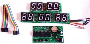
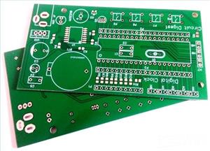
- The system uses two main PCBs: a control unit (with the microcontroller and RTC) and a display unit (housing five smaller boards, each with two 0.8-inch 7-segment displays, totalling ten digits).
- The DS3231 RTC is employed for its precise internal crystal oscillator, providing long-term accuracy without the need for manual correction.
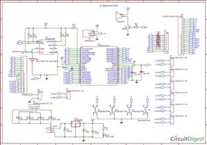
- Multiplexing is used to efficiently control all ten 7-segment displays with fewer microcontroller pins. Segment LEDs are connected in parallel, and display selection is achieved via dedicated control lines split among PORTA, PORTC, and PORTD.
Main Features and Operation
- The large, bright seven-segment displays show hours, minutes, date, month, and year, making the clock easily visible even from across the room.
- Time and date information is continuously read from the DS3231 RTC via I2C communication and displayed.
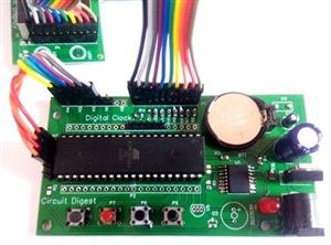
- Four push buttons on the control PCB allow intuitive setting of time and date by navigating and incrementing/decrementing values.
- A 3V coin cell keeps the RTC module powered even if main power is lost, ensuring the clock does not lose time during outages.
- There is scope for expansion: additional displays could show seconds or temperature readings as the PCB is designed with options for such upgrades.
Circuit and Assembly
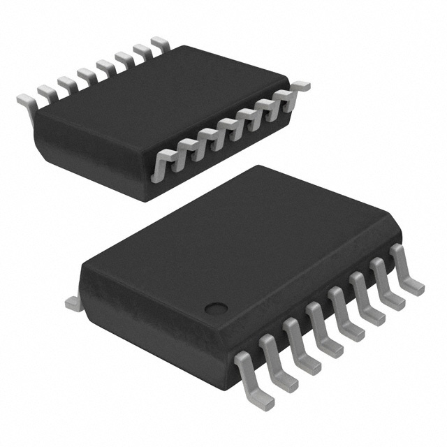
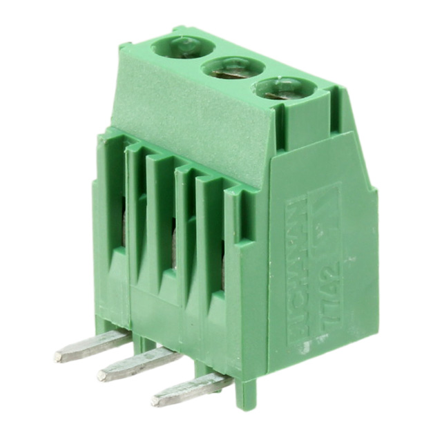
- The control PCB includes the ATmega16 (or pin-compatible ATmega32), DS3231, push buttons, a 7805 voltage regulator, and support components (resistors, capacitors, transistors, buzzer optional).
- Each display sub-board contains two 7-segment displays and indicator LEDs, and all sub-boards connect in parallel to the data bus, with separate enable lines.
- The project includes Gerber files for PCB manufacturing, with step-by-step handling from ordering, assembling, and code uploading.
Practical Use
- Uploading code to the microcontroller and connecting the modules as per the provided circuit will result in a fully operational wall clock.
- The clock is robust, visually appealing, easy to set, and maintains time accurately without regular adjustment, making it ideal for schools, offices, or DIY home use.
This Digital Wall Clock Project uses microcontroller programming, PCB design, multiplexed display control, and reliable real-time clock hardware to create a professional-quality digital wall clock.
Code
Code
C/C++
/*
 * DigitalClock.c
 *
 * Created: 2/28/2019 3:34:56 AM
 *  Author: Saddam
 */
#include<avr/io.h>
#define F_CPU 8000000UL
#include<util/delay.h>
#include<avr/interrupt.h>
int day=6,dd=1,mm=3,yy=19;
unsigned int sec, min=13, hr=4;
const unsigned int num[]={0X40,0X79,0X24,0X30,0X19,0X12,0X02,0X78,0X00,0X10};
int d0,d1,d2,d3,d4,d5,d6,d7,d8,d9;
volatile unsigned int count,count1;
#define digit 13
#define dataPort PORTB
#define controlPortD PORTD
#define controlPortC PORTC
#define controlPortA PORTA
#define controlPortD_Mask 0x83
#define controlPortC_Mask 0x03
#define controlPortA_Mask 0x7F
#define segmentOff -1
#define sw PINA
#define set 4
#define ok 3
#define up 2
#define down 1
#define setEvent (sw & (1<<set))
#define okEvent (sw & (1<<ok))
#define upEvent (sw & (1<<up))
#define downEvent (sw & (1<<down))
#define LEDPORT PORTA
#define secLed 5
#define BUZPORT PORTD
#define buzzer 7
char blinkFlag;
volatile char onFlag=0x00;
#define timeFormat 24
enum
{
hour=1,
minute,
date,
month,
year,
};
char segOn[12]={0x04,0x08,0x10,0x20,0x40,0x80,0x40,0x80,0x10,0x20,0x04,0x08};
void display();
void updateTime();
ISR(TIMER1_OVF_vect)
{
display();
TCNT1 = 64000;
}
void selectSeg(int count)
{
if(count < 5)
{
controlPortA&=controlPortA_Mask;
controlPortC&=controlPortC_Mask;
controlPortD&=controlPortD_Mask;
controlPortD|=segOn[count];
}
else if(count == 5)
{
controlPortA|=segOn[count];
controlPortC&=controlPortC_Mask;
controlPortD&=controlPortD_Mask;
}
else if(count == -1)
{
controlPortA&=controlPortA_Mask;
controlPortC&=controlPortC_Mask;
controlPortD&=controlPortD_Mask;
}
else
{
controlPortA&=controlPortA_Mask;
controlPortC&=controlPortC_Mask;
controlPortD&=controlPortD_Mask;
controlPortC|=segOn[count];
}
}
void segment(int count, int seg)
{
if(blinkFlag == seg)
    {
    if(onFlag)
    selectSeg(segmentOff);
    else
    selectSeg(count);
    }
else
{
selectSeg(count);
}
}
void display()
{
count1++;
if(count1>400)
{
count1=0;
onFlag=!onFlag;
}
count++;
if(count>digit)
count=0;
switch(count%digit)
{
case 0:
segment(count,minute);
dataPort=num[d0];
break;
case 1:
segment(count,minute);
dataPort=num[d1];
break;
case 2:
segment(count,hour);
dataPort=num[d2];
break;
case 3:
segment(count,hour);
dataPort=num[d3];
break;
case 4:
segment(count,date);
dataPort=num[d4];
break;
case 5:
segment(count,date);
dataPort=num[d5];
break;
case 6:
segment(count,month);
dataPort=num[d6];
break;
case 7:
segment(count,month);
dataPort=num[d7];
break;
case 8:
segment(count,year);
dataPort=num[d8];
break;
case 9:
segment(count,year);
dataPort=num[d9];
break;
}
}
void timer1_init()
{
// set up timer with prescaler = 8
TCCR1B |= (1 << CS11);
//TCCR1B &= ~(1 << CS10);
//TCCR1B &= (1 << CS11);
//TCCR1B &= ~(1 << CS12);
TCNT1 = 63500;
TIMSK |= (1 << TOIE1);
sei();
}
int bcdtochar(char num)
{
return ((num/16 * 10) + (num % 16));
}
int dectobcd(char num)
{
return ((num/10)<<4) + (num % 10);
}
void RTC_start()
{
TWCR=(1<<TWINT)|(1<<TWSTA)|(1<<TWEN);
while((TWCR&0x80)==0x00);
}
void device()
{
TWDR=0xD0;                                         //RTC write (slave address)
TWCR=(1<<TWINT)|(1<<TWEN);
while(!(TWCR&(1<<TWINT)));
TWDR=0x00;                                        // word address write
TWCR=(1<<TWINT)|(1<<TWEN);
while(!(TWCR&(1<<TWINT)));
}
void RTC_stp()
{
TWCR=(1<<TWINT)|(1<<TWEN)|(1<<TWSTO);           //stop communication
}
void RTC_read()
{
TWCR=(1<<TWINT)|(1<<TWSTA)|(1<<TWEN);
while((TWCR&0x80)==0x00);
TWDR=0xD0;                                         //RTC write (slave address)
TWCR=(1<<TWINT)|(1<<TWEN);
while(!(TWCR&(1<<TWINT)));
TWDR=0x00;                                         //RTC write (word address)
TWCR=(1<<TWINT)|(1<<TWEN);
while(!(TWCR&(1<<TWINT)));
TWCR=(1<<TWINT)|(1<<TWSTA)|(1<<TWEN);              //start RTC  communication again
while ((TWCR&0x80)==0x00);
TWDR=0xD1;                                        // RTC command to read
TWCR=(1<<TWINT)|(1<<TWEN);
while(!(TWCR&(1<<TWINT)));
}
void sec_init(unsigned char d)
{
TWDR=d;                                       //second init
TWCR=(1<<TWINT)|(1<<TWEN);
while(!(TWCR&(1<<TWINT)));
}
void min_init(unsigned char d)
{
TWDR=d;                                       //minute init
TWCR=(1<<TWINT)|(1<<TWEN);
while(!(TWCR&(1<<TWINT)));
}
void hr_init(unsigned char d)
{
TWDR=d;                                        //hour init
TWCR=(1<<TWINT)|(1<<TWEN);
while(!(TWCR&(1<<TWINT)));
}
void day_init(unsigned char d)
{
TWDR=d;                                          //days init
TWCR=(1<<TWINT)|(1<<TWEN);
while(!(TWCR&(1<<TWINT)));
}
void date_init(unsigned char d)
{
TWDR=d;                                          //date init
TWCR=(1<<TWINT)|(1<<TWEN);
while(!(TWCR&(1<<TWINT)));
}
void month_init(unsigned char d)
{
TWDR=d;                                         //month init
TWCR=(1<<TWINT)|(1<<TWEN);
while(!(TWCR&(1<<TWINT)));
}
void yr_init(unsigned char d)
{
TWDR=d;                                         //year init
TWCR=(1<<TWINT)|(1<<TWEN);
while(!(TWCR&(1<<TWINT)));
}
int sec_rw()
{
int g[3];
TWCR|=(1<<TWINT)|(1<<TWEA);                         //RTC second read
while((TWCR & 0x80)==0x00);
return bcdtochar(TWDR);
}
int min_rw()
{
TWCR|=(1<<TWINT);                                   //RTC minute read
TWCR|=(1<<TWEA);
while((TWCR & 0x80)==0x00);
return bcdtochar(TWDR);
}
int hr_rw()
{
TWCR|=(1<<TWINT)|(1<<TWEA);                         //RTC hour read
while((TWCR & 0x80)==0x00);
return bcdtochar(TWDR);
}
int day_rd()
{
TWCR|=(1<<TWINT)|(1<<TWEA);                         //RTC day read
while((TWCR&0x80)==0x00);
return bcdtochar(TWDR);
}
int date_rw()
{
TWCR|=(1<<TWINT)|(1<<TWEA);                      //RTC date read
while((TWCR & 0x80)==0x00);
return bcdtochar(TWDR);
}
int month_rw()
{
TWCR|=(1<<TWINT)|(1<<TWEA);                     //RTC month read
while((TWCR & 0x80)==0x00);
return bcdtochar(TWDR);
}
int yr_rw()
{
TWCR|=(1<<TWINT);                                 //RTC year read
TWCR&=(~(1<<TWEA));
while((TWCR & 0x80)==0x00);
return bcdtochar(TWDR);
}
void setTime()
{
RTC_start();
device();
sec_init(0);
min_init(dectobcd(min));
hr_init(dectobcd(hr));
day_init(dectobcd(day));
date_init(dectobcd(dd));
month_init(dectobcd(mm));
yr_init(dectobcd(yy));
RTC_stp();
}
void RTC()
{
RTC_read();
sec=sec_rw();
min=min_rw();
hr=hr_rw();
day=day_rd();
dd=date_rw();
mm=month_rw();
yy=yr_rw();
RTC_stp();
}
char getPara(char count)
{
while(1)
{
updateTime();
if(!upEvent)
{
count1=0;
onFlag=0x00;
count++;
if(blinkFlag == hour)
{
if(timeFormat == 12)
{
if(count>12)
count=0;
}
else
{
if(count > 23)
count=0;
}
hr=count;
}
else if(blinkFlag == minute)
{
if(count>59)
count=0;
min=count;
}
else if(blinkFlag == month)
{
if(count > 12)
count=1;
mm=count;
}
else if(blinkFlag == date)
{
if(mm == 4 || mm == 6  || mm == 9  || mm == 11)
{
if(count > 30)
count=1;
}
else if(mm == 1 || mm == 3  || mm == 5  || mm == 7 || mm == 8  || mm == 10  || mm == 12)
{
if(count >31)
count=1;
}
else
{
int y=2000+yy;
if(y/4 == 0 && y/400 == 0)
{
if(count > 29)
count=1;
}
else
{
if(count > 28)
count=1;
}
}
dd=count;
}
else if(blinkFlag == year)
{
if(count >99)
count=0;
yy=count;
}
_delay_ms(200);
}
else if(!(downEvent))
{
count--;
if(blinkFlag == year)
{
if(count<0)
count=99;
}
_delay_ms(100);
}
else if(!okEvent)
{
_delay_ms(1000);
return count;
}
}
}
void settingTime()
{
blinkFlag=1;
hr=getPara(hr);
blinkFlag++;
min=getPara(min);
blinkFlag++;
dd=getPara(dd);
blinkFlag++;
mm=getPara(mm);
blinkFlag++;
yy=getPara(yy);
blinkFlag=0;
}
void updateTime()
{
d0=min%10;
d1=min/10;
d2=hr%10;
d3=hr/10;
d4=dd%10;
d5=dd/10;
d6=mm%10;
d7=mm/10;
d8=yy%10;
d9=yy/10;
}
int main(void)
{
unsigned long int Time;
DDRB=0xff;
DDRA=0xE0;
PORTA=0x1E;
DDRD=0xff;
DDRC=0xff;
timer1_init();
    while(1)
    {
RTC();
updateTime();
_delay_ms(500);
LEDPORT|=1<<secLed;
_delay_ms(500);
LEDPORT&=~(1<<secLed);
if (!setEvent)
{
settingTime();
setTime();
}
    }
}
Sep 15,2025
488 views
Digital Wall Clock on PCB using AVR Microcontroller Atmega16 and DS3231 RTC
Build a striking digital wall clock using ATmega16 and DS3231 RTC—modular, precise, and perfect for DIY timekeeping on a custom PCB.
488
0
1
Published: Sep 15,2025
Standard PCB
Download Gerber file 3
PCBWay Donate 10% cost To Author
Only PCB
*PCBWay community is a sharing platform. We are not responsible for any design issues and parameter issues (board thickness, surface finish, etc.) you choose.


Under the
Attribution-MIT
License.


Raspberry Pi 5 7 Inch Touch Screen IPS 1024x600 HD LCD HDMI-compatible Display for RPI 4B 3B+ OPI 5 AIDA64 PC Secondary Screen(Without Speaker)
BUY NOW


Topic

- Comments(1)
- Likes(0)
Upload photo
You can only upload 5 files in total. Each file cannot exceed 2MB. Supports JPG, JPEG, GIF, PNG, BMP
0 / 10000
 More by Rinme Tom
-
 Battery Powered Attendance system using Face Recognition on ESP32-CAM Board
Project OverviewThis project presents a face–recognition–based attendance system built using the ESP...
Battery Powered Attendance system using Face Recognition on ESP32-CAM Board
Project OverviewThis project presents a face–recognition–based attendance system built using the ESP...
-
 Design and Build an Arduino Based Touch Capacitive Piano with Recording and Replay
Project Overview: Power Bank Circuit on PCBThis project is a clean, compact, and integrated power ba...
Design and Build an Arduino Based Touch Capacitive Piano with Recording and Replay
Project Overview: Power Bank Circuit on PCBThis project is a clean, compact, and integrated power ba...
-
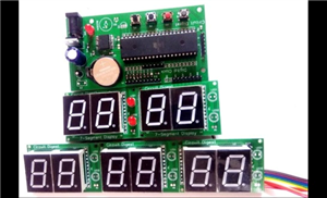 Digital Wall Clock on PCB using AVR Microcontroller Atmega16 and DS3231 RTC
Project Overview This digital wall clock project is a modular, PCB-based timekeeping system using an...
Digital Wall Clock on PCB using AVR Microcontroller Atmega16 and DS3231 RTC
Project Overview This digital wall clock project is a modular, PCB-based timekeeping system using an...
-
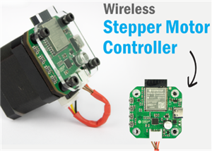 Wireless Stepper Motor Controller with ESP32 and TMC2240
Project OverviewThis wireless stepper motor controller integrates an ESP32-S3 microcontroller with a...
Wireless Stepper Motor Controller with ESP32 and TMC2240
Project OverviewThis wireless stepper motor controller integrates an ESP32-S3 microcontroller with a...
-
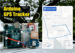 Arduino Location Tracker using SIM800L GSM Module and NEO-6M GPS Module
Project OverviewThis in-depth tutorial illustrates how to develop an affordable real-time GPS tracki...
Arduino Location Tracker using SIM800L GSM Module and NEO-6M GPS Module
Project OverviewThis in-depth tutorial illustrates how to develop an affordable real-time GPS tracki...
You may also like
-
-
ARPS-2 – Arduino-Compatible Robot Project Shield for Arduino UNO
1262 0 4 -
A Compact Charging Breakout Board For Waveshare ESP32-C3
1776 3 7 -
AI-driven LoRa & LLM-enabled Kiosk & Food Delivery System
1756 2 0 -
-
-
-
ESP32-C3 BLE Keyboard - Battery Powered with USB-C Charging
1929 0 1 -


