


|
|
Arduino® Nano V3Arduino
|
x 1 | |
|
|
ERA-2AEB8661XPanasonic
|
x 1 | |
|
|
Piezoelectric Buzzer |
x 1 |

|
Arduino nanoArduino
|
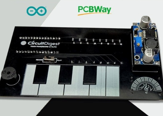
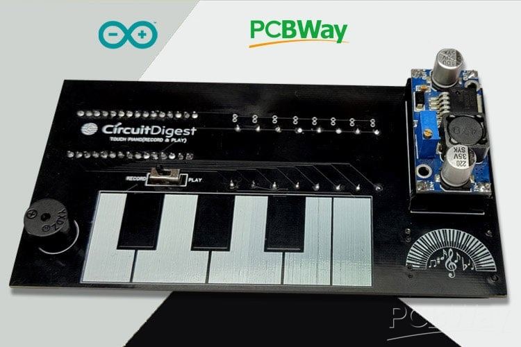
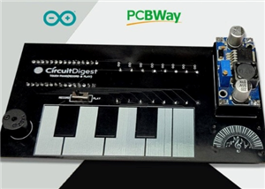
Design and Build an Arduino Based Touch Capacitive Piano with Recording and Replay
Project Overview: Power Bank Circuit on PCB
This project is a clean, compact, and integrated power bank design implemented on a single PCB, using a 18650 lithium cell as the energy source. It combines both battery‐charging and boost‐converter circuits to enable both charging the battery and powering a mobile device from the same board.
Key Features
Single-PCB Integration: Instead of using separate modules for charging and boost conversion, all components (battery charger, boost converter, power switching) are mounted on one PCB. This makes for a neater, more compact design.
Charging Circuit: Utilises the TP4056 IC to manage charging of the 18650 battery cell. Includes safety/regulation features typical of TP4056 circuits.
Boost Converter: Uses the XL6009 IC to step up the battery’s nominal 3.7 V to ~4.5-6 V for USB output to charge a mobile device. A potentiometer lets the user adjust the output voltage.
Mode Switching: A slide switch is included so the user can select whether the device is in “battery-charging” mode or “USB-output” mode (for charging a mobile device).
Components & Layout Highlights
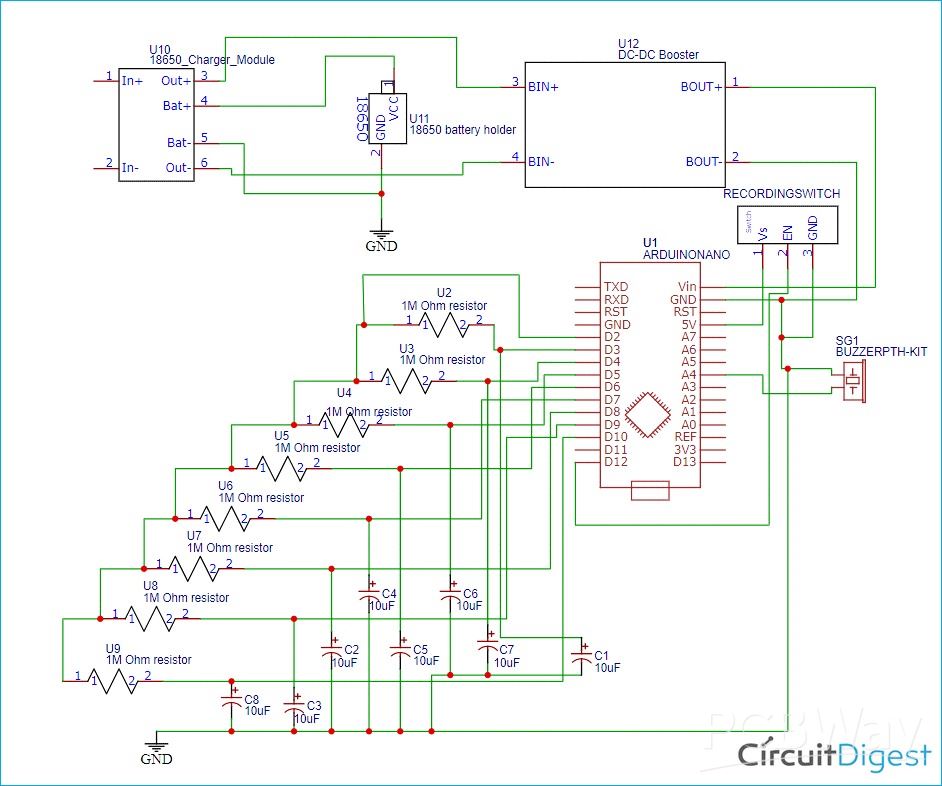
- Core Components: TP4056 charger IC, XL6009 DC-DC boost converter, inductor (33 µH), diodes (1N5824), assorted capacitors (10 µF, 47 µF, 100 µF, 220 µF), resistors, potentiometer, USB connectors, LEDs.
- PCB Design Tool: Designed using EasyEDA. Gerber files, schematics, and all layout layers (top, bottom, silkscreen, etc.) are made available.
- Fabrication: The design is compatible with standard PCB fabrication (e.g. from manufacturers like JLCPCB), supporting typical materials, copper layers, and finishing. The project includes photo-views of the PCB before manufacturing.
Why This Project Is Valuable
- Offers a hands-on PCB project that merges both charging & boosting, helping learners understand power electronics, component selection, and switching/regulation.
- Demonstrates real PCB design workflows: schematic capture, layout, public sharing of Gerber files, ordering PCBs, and component placement.
- Ideal for those wanting to build a custom power bank, or to adapt/extend the design (e.g. changing cell type, output voltage, enclosure).
#include <CapacitiveSensor.h>
#include "piano_tones.h"
#define common_pin 2 // The common ‘send’ pin for all resistors
#define buzzer A4 // The output pin for the piezo buzzer
#define recordbtn 12 // The recording button
// This macro creates a capacitance sensor object for each resistor pins
#define CPin(pin) CapacitiveSensor(common_pin, pin)
char button = 0;
int analogVal;
char REC = 0;
int recorded_button[200];
int pev_button;
int sensitivity = 2000;
int recorded_time[200];
char time_index;
char button_index = 0;
unsigned long start_time;
int note_time;
// Each key corresponds to a note, which are defined here. Uncomment the scale that you want to use:
//int notes[]={NOTE_C4,NOTE_D4,NOTE_E4,NOTE_F4,NOTE_G4,NOTE_A4,NOTE_B4,NOTE_C5}; // C-Major scale
//int notes[]={NOTE_A4,NOTE_B4,NOTE_C5,NOTE_D5,NOTE_E5,NOTE_F5,NOTE_G5,NOTE_A5}; // A-Minor scale
//int notes[]={NOTE_C4,NOTE_D4,NOTE_E4,NOTE_F4,NOTE_G4,NOTE_A4,NOTE_C5,NOTE_D5}; // C Blues scale
//int notes[] = {1300, 1500, 1700, 1900, 2000, 2300, 2600, 2700};
int notes[]={NOTE_C7,NOTE_D7,NOTE_E7,NOTE_F7,NOTE_G7,NOTE_A7,NOTE_B7,NOTE_C8};
//int notes[] = {1915, 1700, 1519, 1432, 1275, 1136, 1014, 956};
// Sound on startup
int soundOnStartUp[] = {
  NOTE_E7, NOTE_E7, 0, NOTE_E7,
  0, NOTE_C7, NOTE_E7, 0,
  NOTE_G7, 0, 0,  0,
  NOTE_G6, 0, 0, 0
};
// Defines the pins that the registers are connected to:
CapacitiveSensor keys[] = {CPin(3), CPin(4), CPin(5), CPin(6), CPin(7), CPin(8), CPin(9), CPin(10)};
void setup(){
  Serial.begin(9600);
// Turn off autocalibrate on all channels:
for(int i=0; i<8; ++i) {
keys[i].set_CS_AutocaL_Millis(0xFFFFFFFF);
}
// Set the buzzer as an output:
pinMode(buzzer, OUTPUT);
pinMode(recordbtn, INPUT);
noTone(buzzer);
delay(10);
    int sizeed = sizeof(soundOnStartUp) / sizeof(int);
    for (int thisNote = sizeed; thisNote > 0 ; thisNote--) {
       tone(buzzer, soundOnStartUp[thisNote]);
       delay(100);
    }
noTone(buzzer);
delay(10);
}
void loop() {
  Serial.println(digitalRead(recordbtn));
  while (digitalRead(recordbtn) == 1) //If the toggle switch is set in recording mode
  {
    recordButtons();
    playTone();
  }
  while (digitalRead(recordbtn) == 0) //If the toggle switch is set in Playing mode
  {
  for (int i = 0; i < sizeof(recorded_button) / 2; i++)
  {
    delay((recorded_time[i]) * 10); //Wait for before paying next tune
    if (recorded_button[i] == 0)
      noTone(buzzer); //user didnt touch any button
    else
      tone(buzzer, notes[(recorded_button[i] - 1)]); //play the sound corresponding to the button touched by the user
  }
  }
}
void recordButtons(){
  // Set the sensitivity of the sensors.
  long touch1 =  keys[0].capacitiveSensor(sensitivity);
  long touch2 =  keys[1].capacitiveSensor(sensitivity);
  long touch3 =  keys[2].capacitiveSensor(sensitivity);
  long touch4 =  keys[3].capacitiveSensor(sensitivity);
  long touch5 =  keys[4].capacitiveSensor(sensitivity);
  long touch6 =  keys[5].capacitiveSensor(sensitivity);
  long touch7 =  keys[6].capacitiveSensor(sensitivity);
  long touch8 =  keys[7].capacitiveSensor(sensitivity);
   pev_button = button;
   // When we touched the sensor, the the button will record the corresponding numbers.
  if (touch1 > sensitivity)
    button = 1;
  if (touch2 > sensitivity)
    button = 2;
  if (touch3 > sensitivity)
    button = 3;
  if (touch4 > sensitivity)
    button = 4;
  if (touch5 > sensitivity)
    button = 5;
  if (touch6 > sensitivity)
    button = 6;
  if (touch7 > sensitivity)
    button = 7;
  if (touch8 > sensitivity)
    button = 8;
  // When we didn't touch it, no tone is produced.
  if (touch1<=sensitivity  &  touch2<=sensitivity  &  touch3<=sensitivity & touch4<=sensitivity  &  touch5<=sensitivity  &  touch6<=sensitivity &  touch7<=sensitivity &  touch8<=sensitivity)
    button = 0;
  /****Rcord the pressed buttons in a array***/
  if (button != pev_button && pev_button != 0)
  {
    recorded_button[button_index] = pev_button;
    button_index++;
    recorded_button[button_index] = 0;
    button_index++;
  }
/**End of Recording program**/
  }
void playTone(){
   /****Rcord the time delay between each button press in a array***/
  if (button != pev_button)
  {
    note_time = (millis() - start_time) / 10;
    if(note_time!=0){
      recorded_time[time_index] = note_time;
    time_index++;
    start_time = millis();
      }
Serial.println(time_index);
  }
  /**End of Recording program**/
  if (button == 0)
  {
    noTone(buzzer);
  }
  if (button == 1)
  {
    tone(buzzer, notes[0]);
  }
  if (button == 2)
  {
    tone(buzzer, notes[1]);
  }
  if (button == 3)
  {
    tone(buzzer, notes[2]);
  }
  if (button == 4)
  {
    tone(buzzer, notes[3]);
  }
  if (button == 5)
  {
    tone(buzzer, notes[4]);
  }
  if (button == 6)
  {
    tone(buzzer, notes[5]);
  }
  if (button == 7)
  {
    tone(buzzer, notes[6]);
  }
  if (button == 8)
  {
    tone(buzzer, notes[7]);
  }
  }
Design and Build an Arduino Based Touch Capacitive Piano with Recording and Replay
*PCBWay community is a sharing platform. We are not responsible for any design issues and parameter issues (board thickness, surface finish, etc.) you choose.


Raspberry Pi 5 7 Inch Touch Screen IPS 1024x600 HD LCD HDMI-compatible Display for RPI 4B 3B+ OPI 5 AIDA64 PC Secondary Screen(Without Speaker)
BUY NOW


- Comments(1)
- Likes(0)
 More by Rinme Tom
-
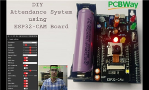 Battery Powered Attendance system using Face Recognition on ESP32-CAM Board
Project OverviewThis project presents a face–recognition–based attendance system built using the ESP...
Battery Powered Attendance system using Face Recognition on ESP32-CAM Board
Project OverviewThis project presents a face–recognition–based attendance system built using the ESP...
-
 Design and Build an Arduino Based Touch Capacitive Piano with Recording and Replay
Project Overview: Power Bank Circuit on PCBThis project is a clean, compact, and integrated power ba...
Design and Build an Arduino Based Touch Capacitive Piano with Recording and Replay
Project Overview: Power Bank Circuit on PCBThis project is a clean, compact, and integrated power ba...
-
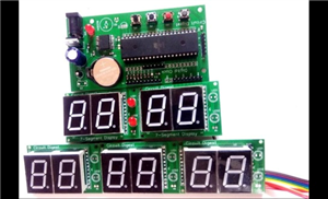 Digital Wall Clock on PCB using AVR Microcontroller Atmega16 and DS3231 RTC
Project Overview This digital wall clock project is a modular, PCB-based timekeeping system using an...
Digital Wall Clock on PCB using AVR Microcontroller Atmega16 and DS3231 RTC
Project Overview This digital wall clock project is a modular, PCB-based timekeeping system using an...
-
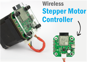 Wireless Stepper Motor Controller with ESP32 and TMC2240
Project OverviewThis wireless stepper motor controller integrates an ESP32-S3 microcontroller with a...
Wireless Stepper Motor Controller with ESP32 and TMC2240
Project OverviewThis wireless stepper motor controller integrates an ESP32-S3 microcontroller with a...
-
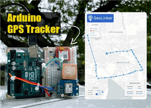 Arduino Location Tracker using SIM800L GSM Module and NEO-6M GPS Module
Project OverviewThis in-depth tutorial illustrates how to develop an affordable real-time GPS tracki...
Arduino Location Tracker using SIM800L GSM Module and NEO-6M GPS Module
Project OverviewThis in-depth tutorial illustrates how to develop an affordable real-time GPS tracki...
-
-
ARPS-2 – Arduino-Compatible Robot Project Shield for Arduino UNO
2462 0 5 -
A Compact Charging Breakout Board For Waveshare ESP32-C3
2900 3 7 -
AI-driven LoRa & LLM-enabled Kiosk & Food Delivery System
3116 2 1 -
-
-
-
ESP32-C3 BLE Keyboard - Battery Powered with USB-C Charging
3162 0 2 -


