


DIY - PCB Christmas Forest
Created a small "PCB Christmas Forest" which is going to light up my study table this Christmas.
In this video, I am going to show you guys how to design these PCBs and assemble them to create a small PCB Christmas Forest.
Designing The PCBs
Sorting Out Images

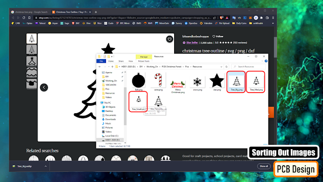
To start the designing process, I need transparent PNG images of the Christmas Tree, Star, Snowflake, Candy Cane etc.
So I went online, and did an "image search" and downloaded few black-and-white images of all the items that I need to design these PCBs.
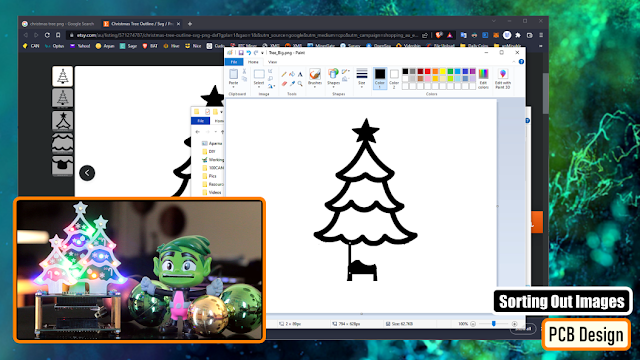
Using the good old "MS Paint" I edited all these PNG files.
I removed the rounded base and made the base flat so that it easily sits on the base plate. Then I removed a small portion from the bottom to expose a bit of copper. Pouring a blob of solder on this plate will hold the PCB nice and tight from the front side on the baseplate.
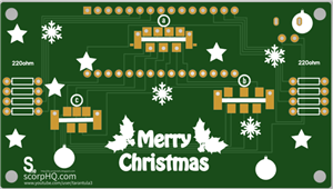
In my design I have 3 different sizes of the trees. If you look closely, they are all extracted from the same tree by removing the bottom layer each time and hence generating a new size of the tree.
Generating DXF File
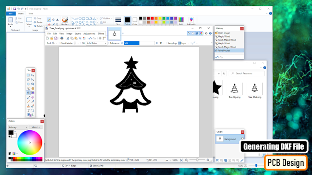
For the customized shapes of the PCBs, we need to generate "DXF files" to set the "Board Outlines". I am using the "paint.net" application to fill in the white spaces of the tress as I only need the borders and nothing else from the original images. Then, I uploaded the images to "https://convertio.co/" and generated the DXF files. This website allows 10 free conversions in a day unless you have a paid account with them.

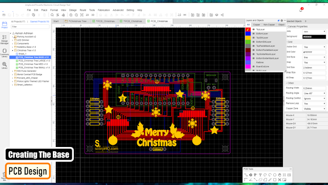
Creating the Trees

Now, lets add a "New PCB" to our project and remove the default board outlines.
Then import the DXF files via File > Import > DXF menu. Make sure you have the "BoardOutLine" selected under layers when you import the dxf file.
Now lets import the image that will go on the Top Silk Layer. Put the image over the board outline and move it to the "TopSilkLayer". Then lets go ahead and decorate our tree. Once all set, lets hide the Top Silk Layer so that we can work on the rest of items.
Using the Rectangle tool from the "PCB Tools Plate" I added a rectangle to the bottom of the PCB. I exposed the copper, so that I can use this to hold the tree on the baseplate by poring a blob of solder on it.
Next I randomly added few LEDs here and there at the bottom side of the board. Then I added few exposed copper rectangles at the back side of the board and connected them the LEDs. Remember this is just an example, the attached gerber is totally different from what you see onscreen.
So, this is how the tree looks like in 3D.
Creating the Baseplate
Now to create the baseplate, we again need to add a "New PCB" to our project and remove the default board outlines.
Then go to Tools > Set Board Outline.. and select the "Round Rectangular" from the "Type" selection. Specify the height, width and the radius of the edge and hit the "Apply" button.
Then go-ahead and add the rest of the components one by one either to the "TopLayer" or the "BottomLayer" of the board and connect them using wires. I grabbed the back and the front exposed rectangles from the tree and added them to the baseplate. This way the spacings will remain intact when we solder the trees on the baseplate. That's it easy as that. Now just go ahead and download your gerber file and send it for fabrication.
So, this is how my baseplate looks like. Bit complex, but it has the exact same logic that I just showed you guys.
Ordering Process
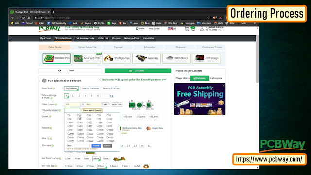
Once I had my design ready, I just had to upload the gerber file to the PCBWay's website and select the type, color and any other customization that I want and then just send it for fabrication.
For my project, I choose the black, red and the green colors.
The Code

The code I wrote is very simple. I have just turned on and off the LEDs after a 500ms delay. The top white LEDs turn on and off in the opposite order to the rest of the LEDs.
This code is just an example, you can write all sorts of funky stuff and load it to your Arduino board.
Testing on Breadboard

I tested my code on a breadboard before soldering the LEDs to the board. I wanted to see if the Arduino Nano can handle that many LEDs at once and I also wanted to check if combining different color LEDs on a same pin of Arduino will have any adverse effect.
The result was pretty promising:
- I was able hook up 3 LEDs without any issues to all the Digital (except D13) and Analogue pins of the Arduino.
- I was "not" able to combine yellow and orange LEDs with any other color on the same pin of Arduino.
Soldering
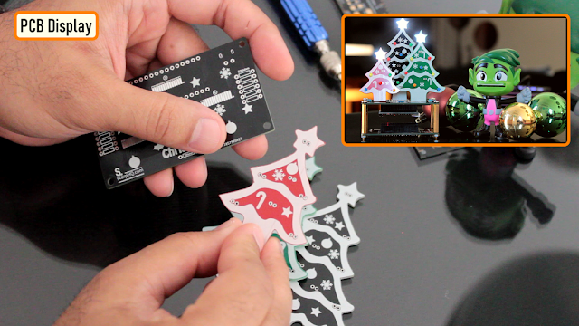
So, this is what came in the mailbag. Have a look at the quality, its absolutely mind-blowing.
Based on my design, the black one will stay at the back, the green one on right and the red one on the left hand side of the baseplate.
Please make sure when you solder the trees, solder the small (red) one first, then the green one and finally the big black one at the back. This way, you will be able to solder them very easily, without going over or under the trees.
Now, lets start soldering.

Lets start by soldering the LEDs on the trees. Since the front side of the plate has all the decorations on it, I placed all the component markings at the back side of the plate.
I then one by one soldered all the LEDs on the front side of the plates.
Please be careful while adding the colors, as mentioned earlier you cannot hook up yellow and orange with any other color on the same pin of an Arduino. Please follow my final coloring patter.

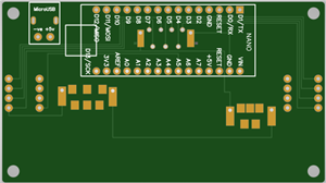
Now lets get the baseplate sorted. Lets start by soldering all the resistances to the board.
Then, lets solder 2 x female pin headers to the board. These pin headers will house the Arduino Microcontroller in it.
After that, lets solder the 2 pin micro-USB port to the board.
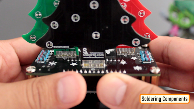
Next, its time to solder the trees to the board. With lots of flux and very little solder this is what I ended up creating.

Since a lot of the LEDs were getting hidden behind the trees, I ended up removing a lot from the final version.
Just follow the onscreen color pattern and you will have a small Christmas forest sitting on your table in less than 30 minutes.
Merry Christmas and Happy New Year...
Thanks
Thanks again for checking my post. I hope it helps you.
If you want to support me subscribe to my YouTube Channel: https://www.youtube.com/user/tarantula3
Video: https://youtu.be/wYbmAVPLWmo
Full Blog Post: http://diy-projects4u.blogspot.com/2022/12/pcb-christmas-forest.html
Code: https://github.com/tarantula3/PCB-Christmas-Forest-v1.0/blob/main/Code.ino
Image Resources : https://github.com/tarantula3/PCB-Christmas-Forest-v1.0/blob/main/Image%20Resources.zip
Gerber v2: https://github.com/tarantula3/PCB-Christmas-Forest-v1.0/tree/main
Support My Work:
BTC: 15cNh9hup8jidCVPwa1DTcxeoh2FPijVrX
LTC: LbquH9Ku78vHtcm3LZnWXpD1JQWdKzeV4v
DOGE: DEB2QBAihnBRhGsaB8P7kz559TDiucQhX6
ETH: 0x5d8c9ba0e54d8354d4af81871db26daa190d2194
BAT: 0x939aa4e13ecb4b46663c8017986abc0d204cde60
LBC: bZ8ANEJFsd2MNFfpoxBhtFNPboh7PmD7M2
COS: bnb136ns6lfw4zs5hg4n85vdthaad7hq5m4gtkgf23 Memo: 572187879
BNB: 0x5d8c9ba0e54d8354d4af81871db26daa190d2194
Thanks, ca again in my next tutorial.
DIY - PCB Christmas Forest
*PCBWay community is a sharing platform. We are not responsible for any design issues and parameter issues (board thickness, surface finish, etc.) you choose.


Raspberry Pi 5 7 Inch Touch Screen IPS 1024x600 HD LCD HDMI-compatible Display for RPI 4B 3B+ OPI 5 AIDA64 PC Secondary Screen(Without Speaker)
BUY NOW


- Comments(0)
- Likes(1)
More by Ashish Adhikari
-
 Arduino Parking Assistant V3
The ESP32-C3 Based Parking Assistant is an advanced parking sensor system that utilizes the ESP32-C3...
Arduino Parking Assistant V3
The ESP32-C3 Based Parking Assistant is an advanced parking sensor system that utilizes the ESP32-C3...
-
 100 LED Chaser Circuit Using IC555 and CD4017
A Chaser Circuit consists of a clocked IC or other electronic unit like an Arduino that drives an ar...
100 LED Chaser Circuit Using IC555 and CD4017
A Chaser Circuit consists of a clocked IC or other electronic unit like an Arduino that drives an ar...
-
 Cute Medusa 3D Printed Humidifier
Humidifiers add moisture to the air. They can help people with dry skin, allergies, and respiratory ...
Cute Medusa 3D Printed Humidifier
Humidifiers add moisture to the air. They can help people with dry skin, allergies, and respiratory ...
-
 4x4x4 PCB LED CUBE
Note from PCBWay: This project includes two PCBs, if both need to be produced, please inform your sa...
4x4x4 PCB LED CUBE
Note from PCBWay: This project includes two PCBs, if both need to be produced, please inform your sa...
-
 Getting Started With Raspberry Pi Pico
Couple of months ago, I bought a "Raspberry Pi Pico" to get some hands-on experience of it and to cr...
Getting Started With Raspberry Pi Pico
Couple of months ago, I bought a "Raspberry Pi Pico" to get some hands-on experience of it and to cr...
-
 ESP32 C3 Super Mini WiFi Fix - 3 Methods That Work
Hi everyone! I’ve recently started working with a tiny, super affordable microcontroller board calle...
ESP32 C3 Super Mini WiFi Fix - 3 Methods That Work
Hi everyone! I’ve recently started working with a tiny, super affordable microcontroller board calle...
-
 Programmable RGB Thermometer
Summer has been relentless this year. My passion for Bitcoin mining took a major hit due to the imme...
Programmable RGB Thermometer
Summer has been relentless this year. My passion for Bitcoin mining took a major hit due to the imme...
-
 All About PC817 Optocoupler
An Optocoupler also known as Photocoupler or Optical Isolator is a component that transfers electric...
All About PC817 Optocoupler
An Optocoupler also known as Photocoupler or Optical Isolator is a component that transfers electric...
-
 Make Your Own 3D Printed Diwali Diyas at Home
Diyas are the heart of major Indian festivals, most notably Diwali, the "Festival of Lights." Lighti...
Make Your Own 3D Printed Diwali Diyas at Home
Diyas are the heart of major Indian festivals, most notably Diwali, the "Festival of Lights." Lighti...
-
 Arduino Based 3D Printed Color Adjustable Minecraft Lantern
For this Halloween, I'm fusing the creative blocky world of Minecraft with the spooky glow of the co...
Arduino Based 3D Printed Color Adjustable Minecraft Lantern
For this Halloween, I'm fusing the creative blocky world of Minecraft with the spooky glow of the co...
-
 3D Printed Breathing IC555 LED Trophy
This project features a custom 3D-printed 'Mortal Kombat' trophy shell paired with a basic NE555 tim...
3D Printed Breathing IC555 LED Trophy
This project features a custom 3D-printed 'Mortal Kombat' trophy shell paired with a basic NE555 tim...
-
 Destiny Internet Ghost - Internet Notifier
The Internet has changed the way we live our lives. From communication, education, banking, entertai...
Destiny Internet Ghost - Internet Notifier
The Internet has changed the way we live our lives. From communication, education, banking, entertai...
-
 Liquid level indicator Using ULN2003
A water level indicator detects and indicates the level of water in an overhead tank and relays the ...
Liquid level indicator Using ULN2003
A water level indicator detects and indicates the level of water in an overhead tank and relays the ...
-
 All About IC UNL2003
The UNL2003 IC contains 7 High Voltage, High Current NPN Darlington Transistor Arrays each rated at ...
All About IC UNL2003
The UNL2003 IC contains 7 High Voltage, High Current NPN Darlington Transistor Arrays each rated at ...
-
 NodeMCU Based: 3D Printed Indoor Gauge Thermometer
Had some time this weekend and a desire to create something new and interesting, so went ahead and c...
NodeMCU Based: 3D Printed Indoor Gauge Thermometer
Had some time this weekend and a desire to create something new and interesting, so went ahead and c...
-
 Rechargeable Gothic Lantern
A Gothic Lantern is a captivating piece of lighting that brings the allure of the Victorian Era into...
Rechargeable Gothic Lantern
A Gothic Lantern is a captivating piece of lighting that brings the allure of the Victorian Era into...
-
 555 Adjustable Delay On Off Timer Circuit
The 555 timer IC is an integrated circuit (IC) that is used in a variety of timer, delay, pulse gene...
555 Adjustable Delay On Off Timer Circuit
The 555 timer IC is an integrated circuit (IC) that is used in a variety of timer, delay, pulse gene...
-
 3D Printed Arduino Halloween Décor
When the full moon is shining and the wolves are howling, it's time for Halloween's spooky spectacle...
3D Printed Arduino Halloween Décor
When the full moon is shining and the wolves are howling, it's time for Halloween's spooky spectacle...
-
Programmable Mist Maker - XIAO / QT PY Extension
399 0 0 -
RadioHAT - Raspberry Pi radio development platform
313 0 1 -
-
-
-
-
ARPS-2 – Arduino-Compatible Robot Project Shield for Arduino UNO
2865 0 6 -
A Compact Charging Breakout Board For Waveshare ESP32-C3
3368 3 8 -
AI-driven LoRa & LLM-enabled Kiosk & Food Delivery System
3685 2 2


