


ESP32 Joystick Hand Controller ESP-NOW
I designed an ESP32 joystick hand controller to wirelessly control the ESP32 Mecanum Wheels (ESP32-Mecanum-Wheels-Robot-and-Bluetooth-Gamepad) robot without using an app. This hand controller is bat-themed and features two thumb joysticks and 4 push-buttons. Check out the video to see how it works...
How It Works?
As seen in the video, I control the mecanum wheels robot wirelessly using joysticks. Here, no radio frequency or Wi-Fi was used for communication, communication was provided via the MAC address, which is easier and safer. There is a way to facilitate this communication ESP-NOW... We can communicate with two ESP32 boards, one-way and two-way.
Printed Circuit Board

The joystick hand controller was made by many makers, usually using an Arduino Nano board and the nRF24L01 or Bluetooth option for communication.
I preferred a bat theme while designing the PCB to have a unique design. I also preferred the ESP32 board, which many of us have heard of, but have some worries about using. In fact, the ESP32 board is more efficient than other boards in terms of communication options. Because an ESP32 board allows Bluetooth, Wi-Fi, MAC address and more wireless communication ways. I also think that it is sufficient on the number of pins compared to other boards. Finally, an ESP32 board is pretty easy to use...
Thank you PCBWay for support and sponsorship in ordering the printed circuit board. For high-quality PCBs, you can choose PCBWay. If you want to get this printed circuit board easily, you can download the PCB Gerber file or order it directly.
Components and Soldering


If you look at the bill of material (BOM), easily solderable components were preferred, so you can easily assembly your printed circuit board by following the circuit diagram designator.
You need few components for the printed circuit board:
- 1x Diode SB560
- 3x Capacitor 100uf 25V
- 2x Thumb Joystick
- 1x Regulator 7805CV
- 2x LED 3mm
- 2x Resistor 330R
- 6x Resistor 4.7K
- 1x ESP32 Devkit V1
- 2x Female Header 1x4 2.54
- 1x Connector 1x2
- 4x Momentary Switch 12mm


Breadboard Circuit
For those who want to experience communicating from ESP32 to ESP32 using ESP-NOW before ordering the printed circuit board, I built two breadboard circuits as sender and receiver. You can build your circuit and test the source code by following the shared circuit diagram.


Getting Board MAC Address


To communicate via ESP-NOW, you need to know the MAC Address of the ESP32 receiver. To get your board’s MAC Address, upload the shared following code. That’s how you know to which device you’ll send the data to. Each ESP32 has a unique MAC Address and this is used to send data using ESP-NOW.
After uploading the code, open the Serial Monitor at a baud rate of 115200 and press the ESP32 RST/EN button. The MAC address should be printed. Save your board MAC address because you’ll need it to send data to the right board. If you want to establish two-way communication between both boards, you will also need the MAC address of the second board.
One-way Point to Point Communication

Let's examine the button-to-motor source code created for the breadboard circuit to simply explain the operation of the source code and ESP-NOW. The circuit to which the button is connected uses the 'Sender' code, while the circuit to which the motor is connected uses the 'Receiver' code.
Once you understand the working principle of these simple codes, you can more easily edit the source code created for Joystick Hand Controller and L293D Motor Board.
Open the shared source code for the Sender-ESP32-Button


- The GPIO pin that the "button" is connected to is defined in the code. Then a variable is defined to read the "button state".
- Next, the MAC address of the receiver-board is entered.
- Then, create a structure that contains the type of data we want to send. Called this structure "struct_message" and it contain an integer variable type (int buttonValue). You can change this to send other types of variables (like char, float, bool).
- When the button is pressed, the value of the button is read and the button state is determined. The button state is sent with the message structure as the button value.
Open the shared source code for the Receiver-ESP32-Motor


- Define the GPIO pin that the "motor" is connected
- Define the message structure to be received from the sender. Must match the sender structure.
- Define a variable for motor state.
- The button value read from the sender is written to the motor state variable, and the motor state variable controls the pin of the motor.
Upload the sender and receiver source codes. Then test it and see how it works. If all is well, you can edit and use the source codes created and shared for Joystick Hand Controller and L293D Motor Driver board.
L293D Motor Driver Board

If you need more details about the L293D Motor Driver board, check out the PCBWay page here: ESP32-Mecanum-Wheels-Robot-and-Bluetooth-Gamepad
In this article, you can find the installation of the mecanum wheels robot and the build and use of the L293D Motor Driver board.
If you have any ideas, please let them know in the comment section. Follow to be informed about the next projects.
ESP32 Joystick Hand Controller ESP-NOW
Project images are for reference only. Actual production is based on the manufacturing files on the project page.
Please review the designer's notes (e.g., PCB thickness) and select the appropriate options.
PCBWay is not responsible
for issues caused by unsuitable parameter selections.
For more important ordering information, please refer to
Read More


Raspberry Pi 5 7 Inch Touch Screen IPS 1024x600 HD LCD HDMI-compatible Display for RPI 4B 3B+ OPI 5 AIDA64 PC Secondary Screen(Without Speaker)
BUY NOW


- Comments(16)
- Likes(19)
- 1 USER VOTES
- YOUR VOTE 0.00 0.00

-
8design
-
8usability
-
8creativity
-
8content
 More by MERT KILIC
-
 3D Printed Theo Jansen Style Octopod Robot (Arduino Based)
Hi everyone! In this project, I will show you an amazing eight-legged robot in the Octopod style! It...
3D Printed Theo Jansen Style Octopod Robot (Arduino Based)
Hi everyone! In this project, I will show you an amazing eight-legged robot in the Octopod style! It...
-
 Creative Modular LED Lighting with Magnetic Pogo Pins & Wi-Fi Control
Hi everyone! Welcome to my latest project: a modular, plug-in LED lighting system that is as fun as ...
Creative Modular LED Lighting with Magnetic Pogo Pins & Wi-Fi Control
Hi everyone! Welcome to my latest project: a modular, plug-in LED lighting system that is as fun as ...
-
 Build a simple 3D printed CNC plotter machine
Hi friends, do you remember this Mini CNC Plotter machine that uses hobby stepper motors and a few 3...
Build a simple 3D printed CNC plotter machine
Hi friends, do you remember this Mini CNC Plotter machine that uses hobby stepper motors and a few 3...
-
 Circuit Activity Board - Educational Electronics
Circuit Activity Board – A Hands-On Project to Learn Basic ElectronicsIn this project, we're going t...
Circuit Activity Board - Educational Electronics
Circuit Activity Board – A Hands-On Project to Learn Basic ElectronicsIn this project, we're going t...
-
 Build a Simple 3D Wall Lighting
Hi friends, this project shows how to make and control 3D hexagonal LED lighting panels. The project...
Build a Simple 3D Wall Lighting
Hi friends, this project shows how to make and control 3D hexagonal LED lighting panels. The project...
-
 Robot Sumo Board
Robot-sumo, or pepe-sumo, is a sport in which two robots attempt to push each other out of a circle ...
Robot Sumo Board
Robot-sumo, or pepe-sumo, is a sport in which two robots attempt to push each other out of a circle ...
-
 ESP32 Mecanum Wheels Robot and Bluetooth Gamepad Controller
In this project we will see how to make an ESP32 Mecanum Wheels Robot which is capable of moving in ...
ESP32 Mecanum Wheels Robot and Bluetooth Gamepad Controller
In this project we will see how to make an ESP32 Mecanum Wheels Robot which is capable of moving in ...
-
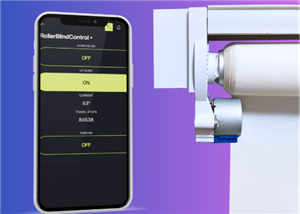
 DIY Motorized WiFi Roller Blind - ESP8266 & Blynk
In this project we will see how to control a roller blind via a smartphone application. The reason w...
DIY Motorized WiFi Roller Blind - ESP8266 & Blynk
In this project we will see how to control a roller blind via a smartphone application. The reason w...
-
 Pet Feeder Controlled Via WiFi - ESP8266
How It Works?As you can see, a 3D design was used for the pet feeder. ESP8266-based Wemos D1 Mini bo...
Pet Feeder Controlled Via WiFi - ESP8266
How It Works?As you can see, a 3D design was used for the pet feeder. ESP8266-based Wemos D1 Mini bo...
-
 ESP8266 Two Wheel Robot (NodeMCU and Stepper Motor)
Generally, robot cars are built on a chassis with 2 DC motor wheels and a bovine wheel. While surfin...
ESP8266 Two Wheel Robot (NodeMCU and Stepper Motor)
Generally, robot cars are built on a chassis with 2 DC motor wheels and a bovine wheel. While surfin...
-
 3D Printed Rotating Table Board with Arduino Nano and 28BYJ-48 Stepper Motor
This project shows how to make a 3D printed Rotating Table using Arduino and a hobby stepper motor. ...
3D Printed Rotating Table Board with Arduino Nano and 28BYJ-48 Stepper Motor
This project shows how to make a 3D printed Rotating Table using Arduino and a hobby stepper motor. ...
-
 Hand Gesture Controller for Robotic
The hand gesture controller makes it possible to control applicat...
Hand Gesture Controller for Robotic
Hand Gesture Controller for RoboticThe hand gesture controller makes it possible to control applicat...
-
 How To Make DIY Remote Control Hoverboat at Home
In this video, I showed you how to make your own hoverboat from materials available at home and chea...
How To Make DIY Remote Control Hoverboat at Home
In this video, I showed you how to make your own hoverboat from materials available at home and chea...
-
 How to Make DIY Arduino Gesture Control Robot at Home
Parts Required for Receiver (Tank):1) Robot Tank Chassis - https://bit.ly/3j8y2Q52) Arduino Nano V3 ...
How to Make DIY Arduino Gesture Control Robot at Home
Parts Required for Receiver (Tank):1) Robot Tank Chassis - https://bit.ly/3j8y2Q52) Arduino Nano V3 ...
-
 DIY Circuit Activty Board with Paperclips | MAKER | STEM
You can be creative and design your own circuit and add different sensors (other LEDs...). The idea ...
DIY Circuit Activty Board with Paperclips | MAKER | STEM
You can be creative and design your own circuit and add different sensors (other LEDs...). The idea ...
-
 ATtiny85 Wearable Activity Tracking Watch
How to make the wearable activity tracking watch? This is a wearable gadget designed to vibrate when...
ATtiny85 Wearable Activity Tracking Watch
How to make the wearable activity tracking watch? This is a wearable gadget designed to vibrate when...
-
 DIY Motorized Roller Blind with ESP32-S3 | WiFi Control, 3D Printed Gear & Blynk Cloud
This project is an updated version of my previous Motorized Roller Blind, which reached nearly 300,0...
DIY Motorized Roller Blind with ESP32-S3 | WiFi Control, 3D Printed Gear & Blynk Cloud
This project is an updated version of my previous Motorized Roller Blind, which reached nearly 300,0...
-
 How to Build a Motorized 3D Scanning Turntable for Your Phone
In this project, I’ll show you how to make a simple motorized turntable for 3D scanning. It has thre...
How to Build a Motorized 3D Scanning Turntable for Your Phone
In this project, I’ll show you how to make a simple motorized turntable for 3D scanning. It has thre...
-
Programmable Mist Maker - XIAO / QT PY Extension
1061 2 1 -
RadioHAT - Raspberry Pi radio development platform
860 0 2 -
-
-
-
-
ARPS-2 – Arduino-Compatible Robot Project Shield for Arduino UNO
3322 0 6 -
A Compact Charging Breakout Board For Waveshare ESP32-C3
3930 3 8 -
AI-driven LoRa & LLM-enabled Kiosk & Food Delivery System
4315 2 2


