IPC standards are the foundation of modern PCB design, manufacturing, and assembly. By providing a unified set of technical requirements, they help engineers improve reliability, manufacturability, and product quality throughout the entire development process. From consumer electronics to industrial control systems, medical devices, and aerospace applications, IPC standards play a critical role in ensuring consistent and repeatable results.
At PCBWay Design Service, engineers regularly review customer layouts against IPC requirements before manufacturing. Common issues such as insufficient annular rings, inadequate creepage distances, improper via structures, and non-compliant footprints can often be identified and corrected during the design review stage, reducing costly revisions later in production.
What Are IPC Standards?
IPC (Association Connecting Electronics Industries) was founded in 1957 and has become the leading standards organization for the electronics interconnection industry. With more than 300 active standards covering PCB materials, design, manufacturing, inspection, and supply chain management, IPC standards provide the foundation for modern electronics development.
Implementing IPC standards offers four key benefits:
- Improved Product Reliability – Prevent trace overheating, via failures, solder joint defects, and other common reliability issues.
- Enhanced Manufacturability – Ensure designs are compatible with standard fabrication and assembly processes, reducing scrap and rework costs.
- Standardized Industry Communication – Establish a common technical language across design, manufacturing, and quality teams.
- Compliance with Industry Requirements – Support certification and quality requirements for medical, automotive, military, and export-oriented electronic products.
Essential IPC Standards for PCB Design
Different IPC standards apply to different stages of PCB development. Understanding their intended use can significantly improve both design efficiency and product quality.
General Design Standards
- IPC-2221: The core standard for IPC PCB design, covering trace width and spacing, electrical clearance, via dimensions, stack-up structures, and basic current-carrying capacity calculations. Applicable to rigid, flexible, and rigid-flex PCBs.
- IPC-2222: A dedicated design standard for rigid PCBs, covering multilayer stack-up symmetry, board warpage control, and mechanical reinforcement. Commonly used in industrial and communication applications.
Material and Quality Acceptance Standards
- IPC-4101: Defines specifications for PCB base materials, including laminates, prepregs, solder masks, and other raw materials, helping engineers select appropriate materials for different reliability levels.
- IPC-6012/6013: Performance standards for rigid and flexible PCBs, specifying plating thickness, annular ring requirements, dimensional tolerances, and acceptance criteria for production.
- IPC-A-600: The industry standard for bare board acceptability, used to evaluate scratches, exposed copper, hole registration issues, solder mask defects, and other PCB quality concerns.
- IPC-A-610: The most widely used PCBA acceptance standard, defining solder joint quality, component placement accuracy, and assembly workmanship requirements.
Electrical and Thermal Management Standards
- IPC-2152: A current-carrying capacity standard used to calculate the current limits and thermal performance of PCB traces and copper planes, helping prevent overheating and circuit failures in high-power designs.
- IPC-2141: Provides guidance for controlled impedance PCB design, including Microstrip, Stripline, and differential impedance structures. Commonly used in high-speed digital, RF, and communication PCB applications.
Footprint and Via Reliability Standards
- IPC-7351: Defines SMT land pattern and footprint design standards, including pad dimensions and solder mask openings, helping reduce solder bridging, tombstoning, and insufficient solder joints.
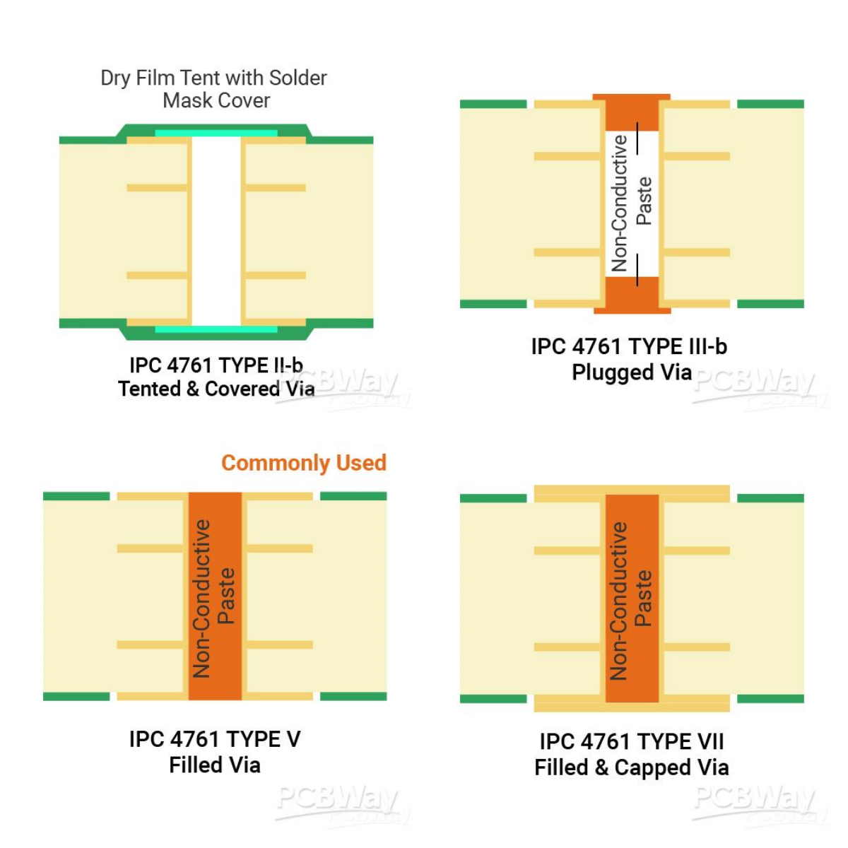
- IPC-4761: Defines PCB via protection and treatment methods, including Via Tenting, Via Plugging, Via Filling, and Via Capping. It is particularly important for HDI boards, BGA layouts, and high-reliability applications.
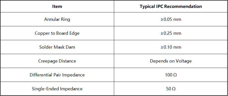
Common IPC Design Rules at a Glance
IPC Product Classes: Choosing the Right Reliability Level
IPC classifies electronic products into three reliability levels. Higher classes require stricter manufacturing tolerances, inspection criteria, and reliability standards. Selecting the appropriate class helps balance performance and production costs.
IPC Class 1 (General Electronic Products)
- Typical Applications: Disposable consumer products, toys, basic remote controls, and simple household appliances.
- Key Characteristics: Focuses on basic functionality, allows a higher level of cosmetic defects, and offers the lowest manufacturing cost.
IPC Class 2 (Dedicated Service Electronics)
- Typical Applications: Industrial controllers, computers, routers, standard medical devices, and general automotive electronics.
- Key Characteristics: Designed for long-term reliable operation while allowing minor imperfections that do not affect functionality. This is the most commonly used IPC class.
IPC Class 3 (High-Reliability Electronics)
- Typical Applications: Aerospace systems, military equipment, automotive safety systems, advanced medical devices, and mission-critical servers.
- Key Characteristics: Requires the highest level of reliability, with tighter manufacturing tolerances, stricter cleanliness requirements, enhanced plating specifications, and rigorous inspection procedures. Class 3/A is commonly used for military and aerospace applications.
IPC standards provide the design rules and acceptance criteria that guide PCB development. However, successful PCB design also requires proper component placement, routing strategies, signal integrity considerations, and manufacturability optimization. For a more comprehensive overview of the complete PCB development process, see our guide: Complete PCB Design Guidelines: Layout, Routing and Manufacturing Best Practices.
Practical Tips for Implementing IPC Standards in PCB Design
With modern PCB design software, IPC standards can be converted into automated design rules to improve efficiency and ensure compliance.
- Define the IPC Class Early: Select the appropriate IPC class based on product requirements and configure trace width, spacing, via dimensions, and solder mask clearances accordingly.
- Standardize Footprint Design: Use IPC-7351 footprint generators to create accurate land patterns and eliminate manual footprint errors.
- Enable DRC Checks: Run design rule checks throughout the layout process to automatically detect violations and reduce costly redesigns. Designers can also use the PCBWay DRC Tool to assist with PCB design validation.
- Generate Standardized Manufacturing Files: Export IPC-2581 production files and supporting DFM reports to ensure compatibility with PCB manufacturers.
Common Mistakes in IPC PCB Design
❌️ Assuming Higher Classes Are Always Better
Not all products require Class 3 standards. Over-specifying reliability requirements can significantly increase manufacturing costs.
❌️ Confusing Design and Acceptance Standards
IPC-2221 governs design practices, while IPC-A-600 and IPC-A-610 define inspection and acceptance criteria. Both are essential.
❌️ Relying on Default Software Settings
High-speed, high-voltage, and high-current PCBs require dedicated calculations and optimization based on IPC-2141 and IPC-2152.
❌️ Ignoring IPC Requirements During Prototyping
A successful prototype does not necessarily guarantee smooth mass production. IPC compliance should be considered from the beginning of the design process.
Conclusion
IPC standards remain one of the most important foundations of successful PCB development. By applying the right standards at each stage of design and manufacturing, engineers can improve reliability, reduce production issues, and streamline the path from concept to mass production.
PCBWay Design Service further supports this process through professional design review, DFM optimization, and manufacturing-oriented engineering assistance, helping ensure that PCB designs are ready for reliable production.


