

UNI-SAT 3U CubeSat – Tracking Aircraft Beyond Radar Coverage
- WHO I AM
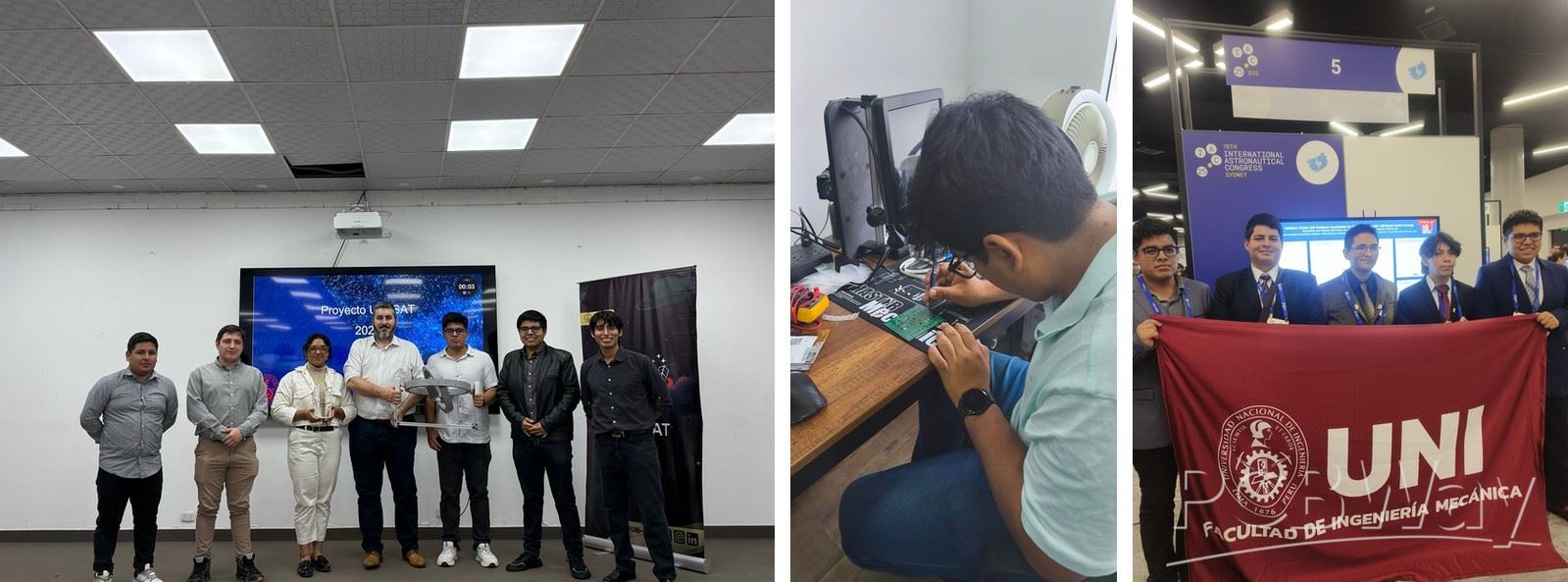
My name is Juan Salvador Palacios Bett and I lead UNI-SAT, the satellite team of the Universidad Nacional de Ingeniería (UNI) in Lima, Peru. We are seven students of Mechatronics and Telecommunications Engineering at UNI, supported by a faculty advisor. We work in our own laboratory with professional soldering stations, 3D printers and electronic test equipment, and we have taken part in national and international engineering events. We also share space technology with students and the public, and we have been invited to interviews in Peruvian media such as La República, TV Perú and the Andina news agency. Our work is already supported with academic licences from SolidWorks, MathWorks, Altium, Ansys and ESSS.
- PROJECT DESCRIPTION
UNI-SAT is a small satellite with a big mission. It follows aircraft where no radar can see them.
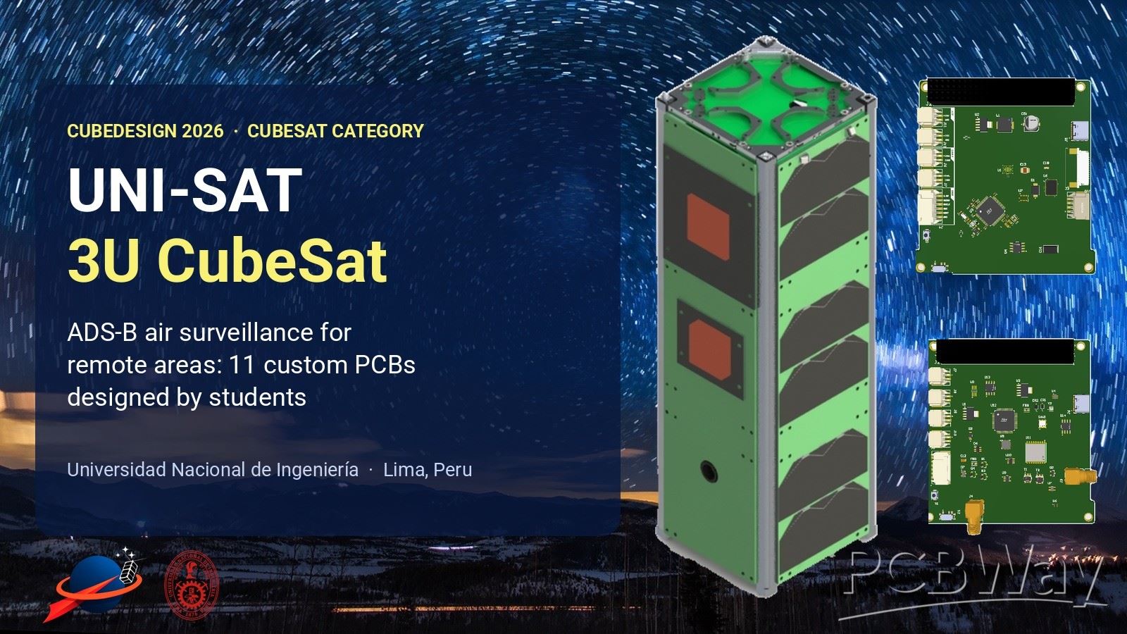
UNI-SAT is a 3U CubeSat (10 × 10 × 34 cm, about 2.1 kg) designed by seven engineering students of the Universidad Nacional de Ingeniería (UNI) in Lima, Peru, with the guidance of a faculty advisor. We are building it for CubeDesign 2026, an international university nanosatellite competition hosted by the nanosatellite laboratory of the Universidad Nacional de San Martín (UNSAM) in Buenos Aires, Argentina. The structure, the electronics, the flight software and the ground station are all designed by the team, and the heart of the satellite is a set of 11 printed circuit board designs that we created in Altium Designer.
- WHY ADS-B FROM SPACE?
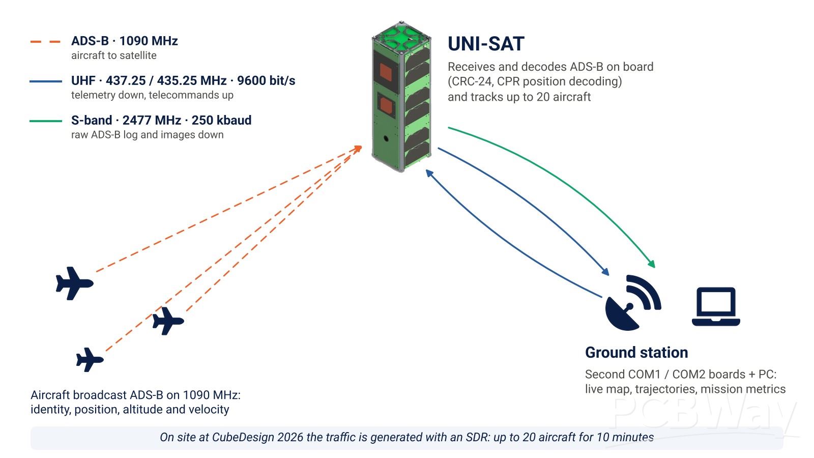
Aircraft continuously broadcast their identity, position, altitude and velocity on 1090 MHz (ADS-B). Ground receivers and radars pick these messages up near airports and cities, but over the ocean, the Amazon rainforest and the Andes there is little or no coverage. A receiver in low Earth orbit hears aircraft across thousands of kilometres and can fill those gaps. For Peru, with a long Pacific coastline, a vast rainforest and high mountains, this is a very real problem.
CubeDesign 2026 turns it into a hands-on challenge. On site, a software-defined radio generates realistic traffic of up to 20 aircraft for 10 minutes. Our satellite has to detect the messages, decode them on board, track every aircraft and deliver the data to our own ground station. It also has to prove its platform: radio links, deployment of its antenna by remote command, battery charging under a lamp, stopping a 60 rpm spin and measuring its orientation with a sun sensor.
- UNI-SAT AT A GLANCE
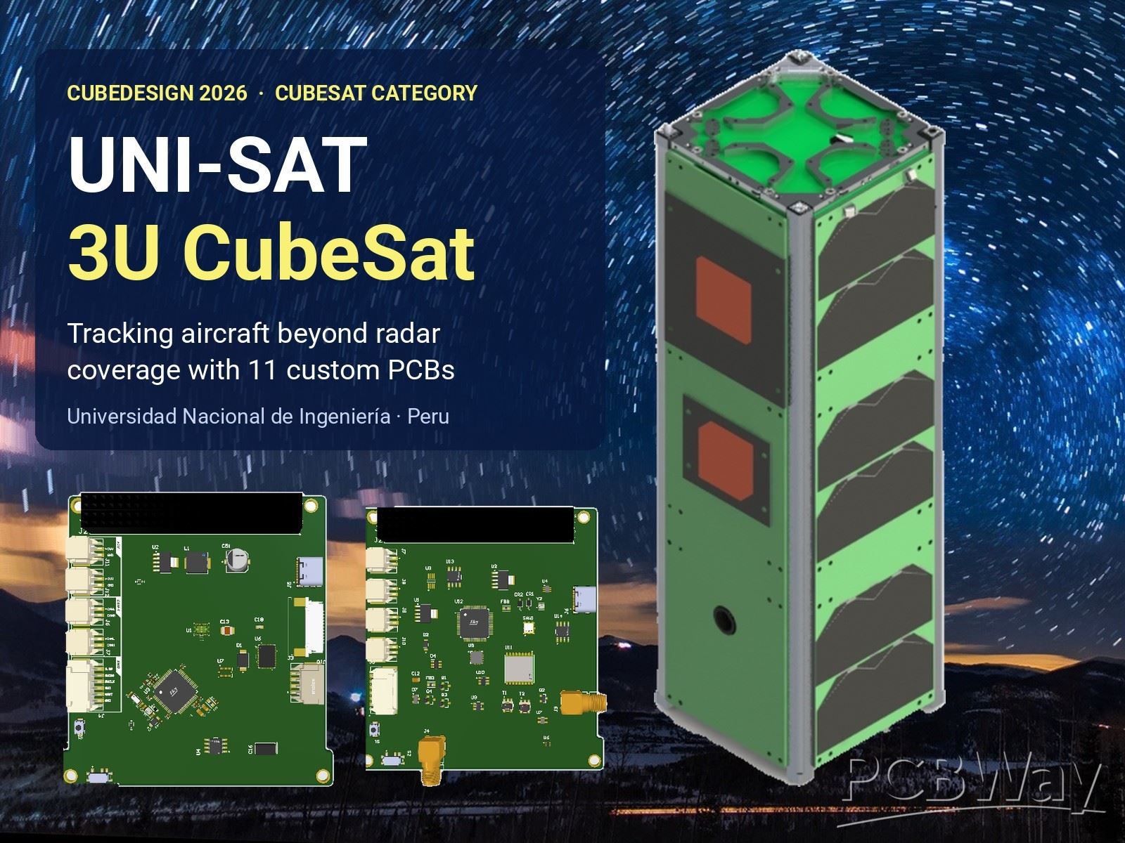
[Insert image 02_at_a_glance.jpg] *SolidWorks model: external view, the stack with the side panels removed, and the opposite corner. From top to bottom: antenna and Mechanisms board, COM1, OBC, PAYLOAD1, COM2, ADCS-2, reaction wheel, ADCS-1, PAYLOAD2, EPS and battery.*
- Format: 3U CubeSat, 100 × 100 × 340.5 mm, about 2.1 kg (estimate)
- Electronics: 11 custom PCB designs, 8 STM32 microcontrollers (one per subsystem), main and redundant CAN bus
- Payloads: ADS-B receiver and decoder with GNSS time-stamping, and a 5 MP camera
- Radios: UHF (437 MHz) telemetry and telecommands with a deployable turnstile antenna, and an S-band (2.4 GHz) high-rate downlink
- Attitude control: reaction wheel (maxon EC 20 flat motor with a brass flywheel), magnetorquers and a photodiode sun sensor
- Power: 12 triple-junction solar cells, 2S2P Li-ion battery (about 49 Wh), MPPT charger and a two-stage hardware inhibit
- Software: µC/OS-III real-time kernel on every board; ground software in C++
- HOW THE SATELLITE IS BUILT
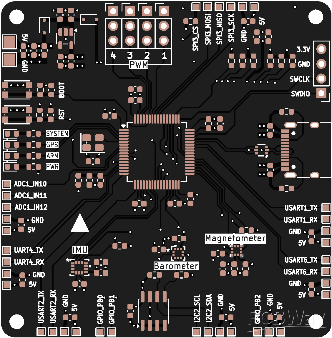
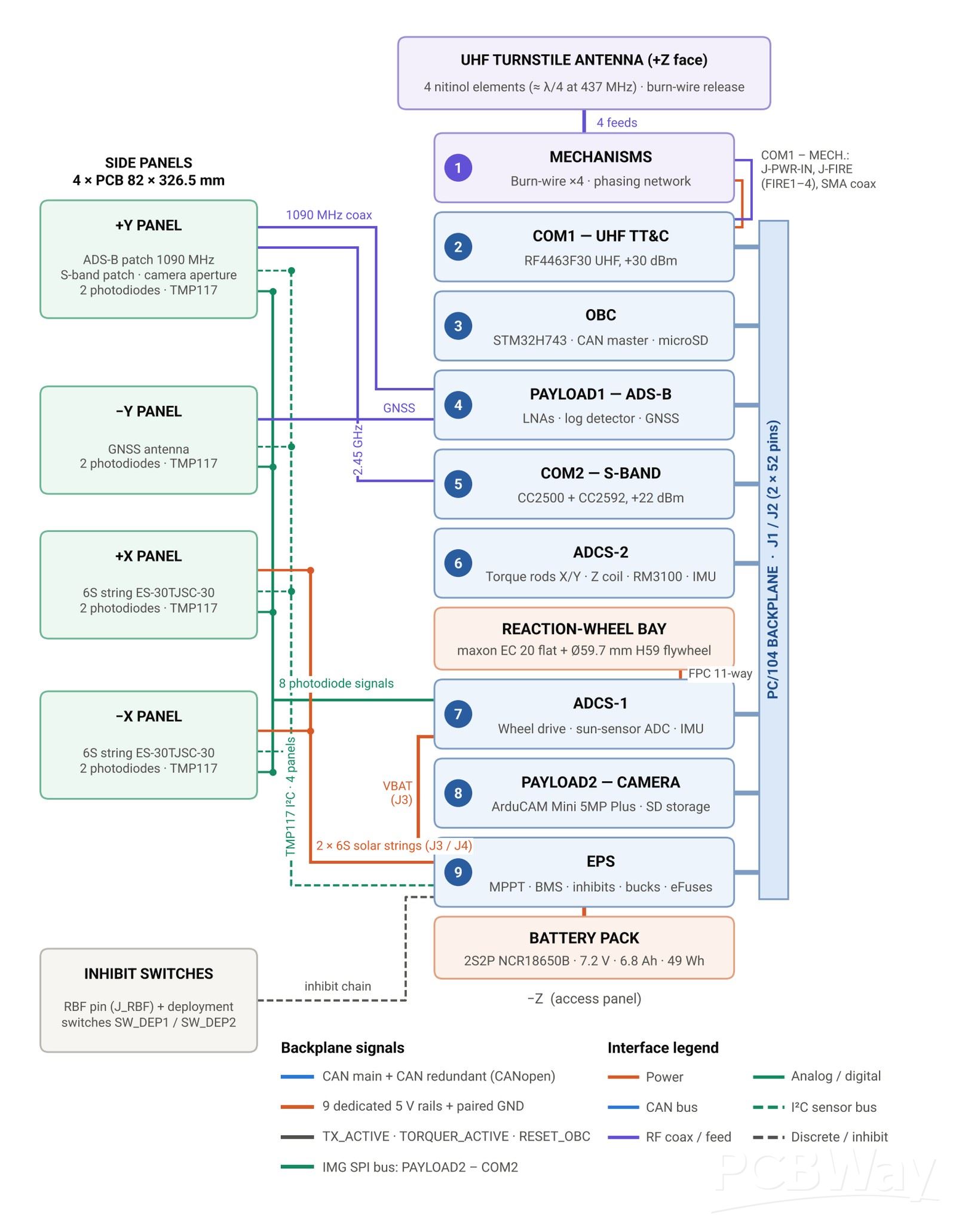
UNI-SAT uses a distributed architecture: every board has its own microcontroller, built from a common, verified schematic template (STM32, crystals, reset and boot, SWD, a USB-C debug port and two CAN transceivers). The boards talk over a main and a redundant CAN bus through the PC/104 stack connector, and the power system feeds each board through its own 5 V rail. Every board can therefore be powered, programmed and tested on its own on the bench. That is also why the quality of each individual PCB matters so much to us.
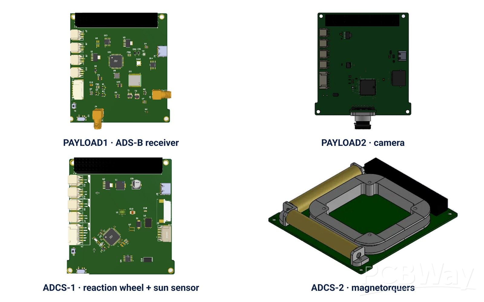
- PAYLOAD1 – ADS-B RECEIVER
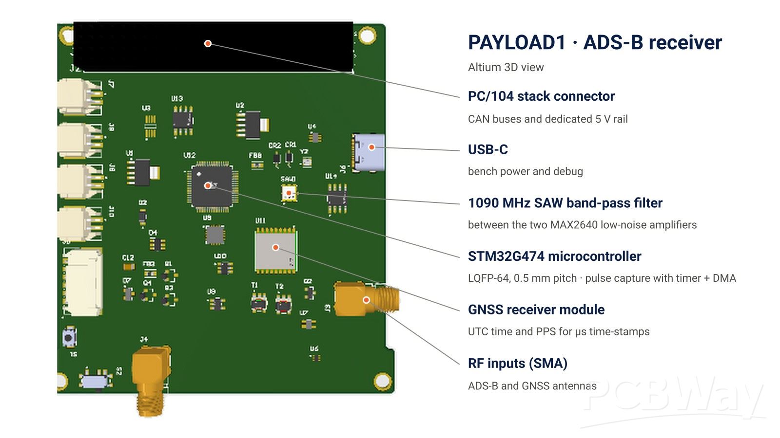
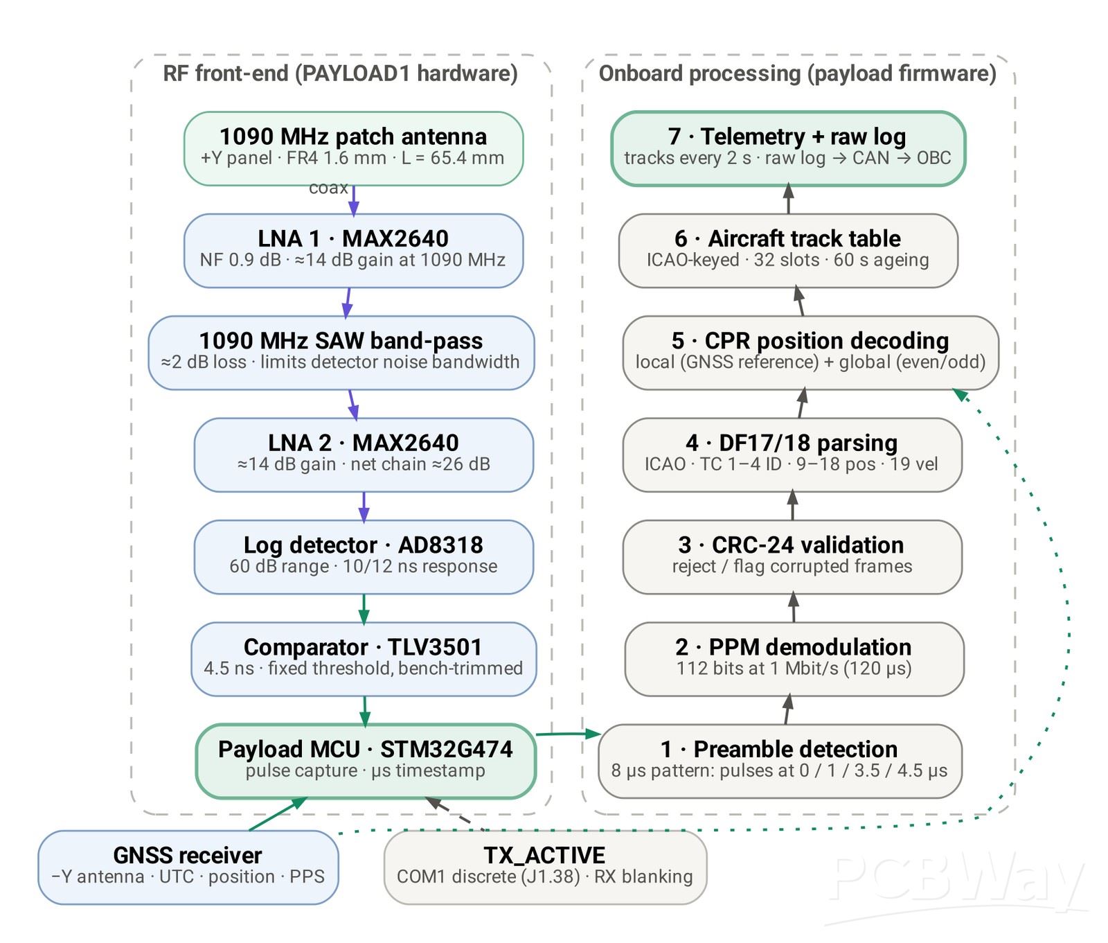
The main payload listens to 1090 MHz. Two MAX2640 low-noise amplifiers, with a 1090 MHz SAW band-pass filter between them, amplify the antenna signal. An AD8318 logarithmic detector turns the RF envelope into a voltage, and a TLV3501 comparator (4.5 ns) slices it into a clean pulse train. An STM32G474 captures every pulse edge with a timer and DMA, and a GNSS module provides UTC time and a PPS pulse for microsecond time-stamps. The firmware detects the 8 µs preamble, demodulates the 112-bit messages, checks the CRC-24, decodes position, altitude and velocity, and keeps a track table of the aircraft in view. The whole RF chain draws only 78 mA at 5 V.
Board quality shows up directly in performance here: the 1090 MHz traces need controlled impedance and solid ground planes, and the detector and comparator handle pulses of a few nanoseconds.
- PAYLOAD2 – CAMERA
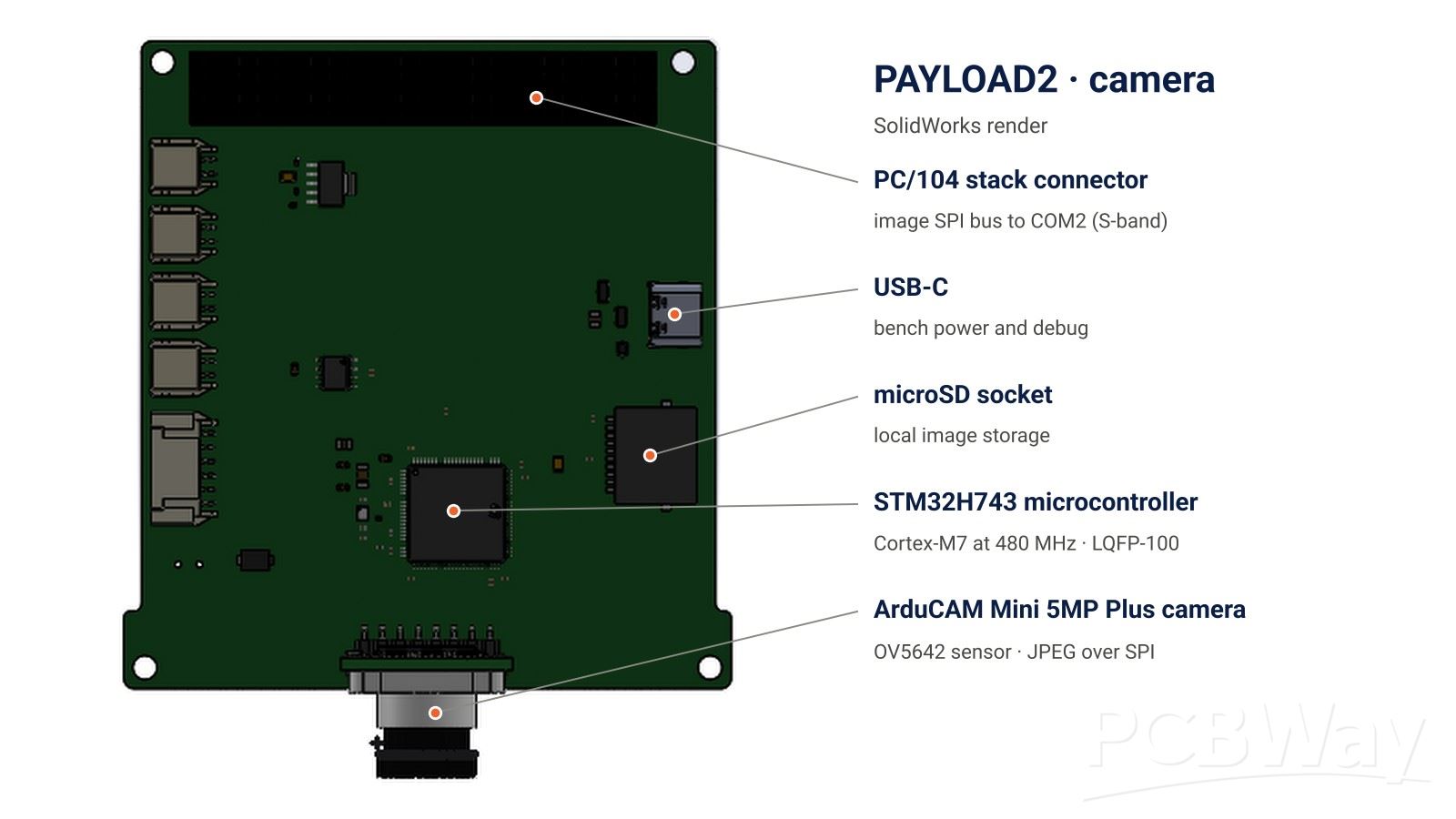
PAYLOAD2 combines an STM32H743 (Cortex-M7, 480 MHz) with an ArduCAM Mini 5MP Plus module (OV5642 sensor with on-module JPEG encoder). It captures context images, stores them on a microSD card and streams them to the S-band radio over a dedicated SPI bus on the backplane, at up to 1 to 2 frames per second in QVGA resolution.
- ADCS-1 – REACTION-WHEEL CONTROL
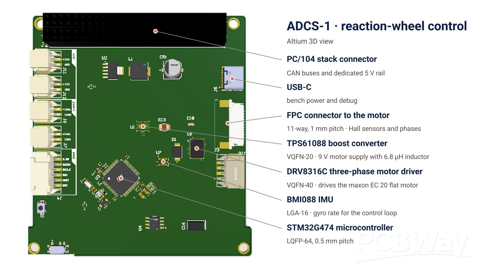
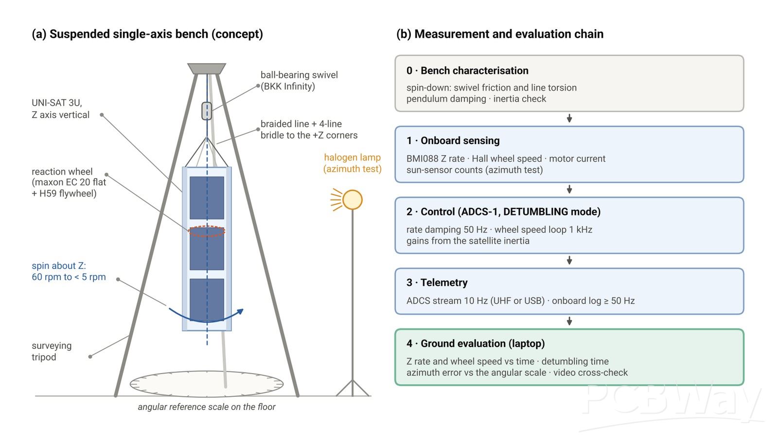
One of the hardest tests of the competition is to stop the satellite from spinning: from 60 rpm to below 5 rpm, ideally in less than 10 seconds. ADCS-1 drives a maxon EC 20 flat brushless motor carrying a 179 g brass flywheel. A DRV8316C three-phase driver (VQFN-40) commutates the motor using its Hall sensors, a TPS61088 boost converter (VQFN-20) raises the battery voltage to 9 V for the motor, and a BMI088 IMU (LGA-16) measures the rotation of the satellite for a 50 Hz rate-damping loop on an STM32G474 (LQFP-64). The same board digitises the eight photodiodes of the sun sensor. In simulation, the wheel removes a 60 rpm spin in about 7.5 s, using a conservative estimate of the satellite inertia.
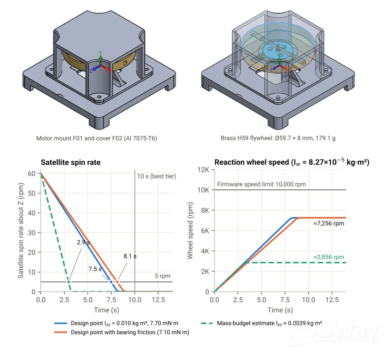
Reaction-wheel assembly in CAD (aluminium mount and cover, brass flywheel) and the detumbling simulation.
- ADCS-2 – MAGNETORQUERS
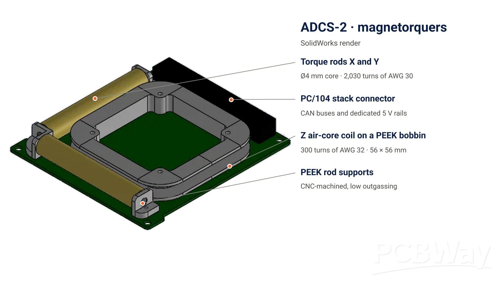
ADCS-2 carries two torque rods (4 mm cores with 2,030 turns of AWG 30 each) and a Z-axis air-core coil wound on a PEEK bobbin, together with an RM3100 magnetometer and a BMI088 IMU. A DRV8833 H-bridge with a hardware current limit drives the rods, which unload the momentum stored in the reaction wheel.
- EPS – ELECTRICAL POWER SYSTEM
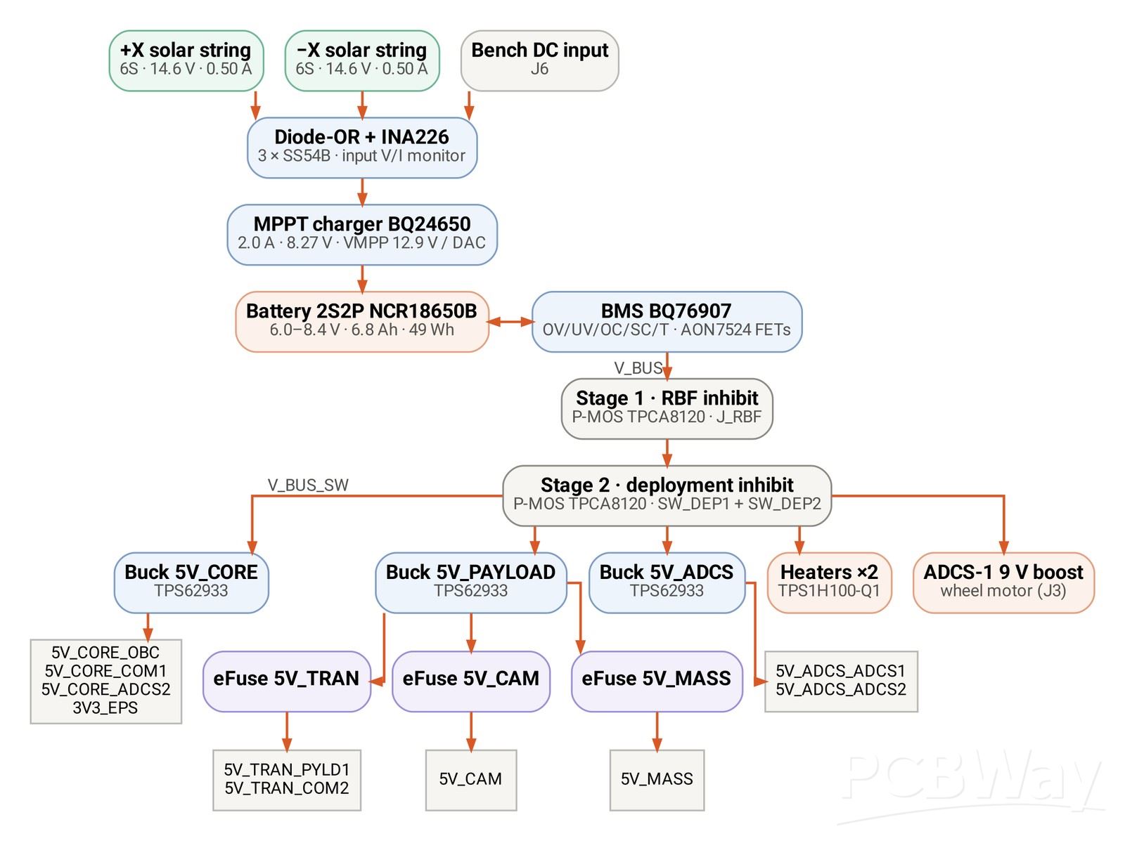
Two strings of six triple-junction space solar cells (ES-30TJSC-30, about 30 % efficiency) charge a 2S2P Li-ion pack (Panasonic NCR18650B, about 49 Wh) through a BQ24650 synchronous MPPT charger. A BQ76907 battery monitor in an isolated domain protects the cells, two heater channels keep them above 0 °C, and a two-stage hardware inhibit (a remove-before-flight pin and two deployment switches, with no microcontroller in the path) keeps the satellite switched off until it is deployed. Three TPS62933 buck converters and three TPS259530 eFuses distribute nine dedicated 5 V rails.
- OBC – ON-BOARD COMPUTER
The OBC (STM32H743) is the system master. It runs the mode manager, controls both CAN buses, keeps the system time and works as the data logger of the satellite, time-stamping every CAN message onto a 128 GB microSD card. It also carries a BMI088 IMU, an RM3100 magnetometer and a 16 MB QSPI flash.
- COM1 AND COM2 – RADIOS AND GROUND STATION
COM1 is the UHF link: an RF4463F30 module (Si4463, +30 dBm, 9600 bit/s) for telecommands, telemetry, the beacon and the antenna release. COM2 is the high-rate S-band downlink: a CC2500 transceiver with a CC2592 front end (+22 dBm, 250 kbaud) for the raw ADS-B log and the images. A second unit of each board, connected over USB-C to a PC running our C++ ground software, is our ground station, so the same PCB designs fly in the satellite and receive on the ground.
- MECHANISMS AND SIDE PANELS
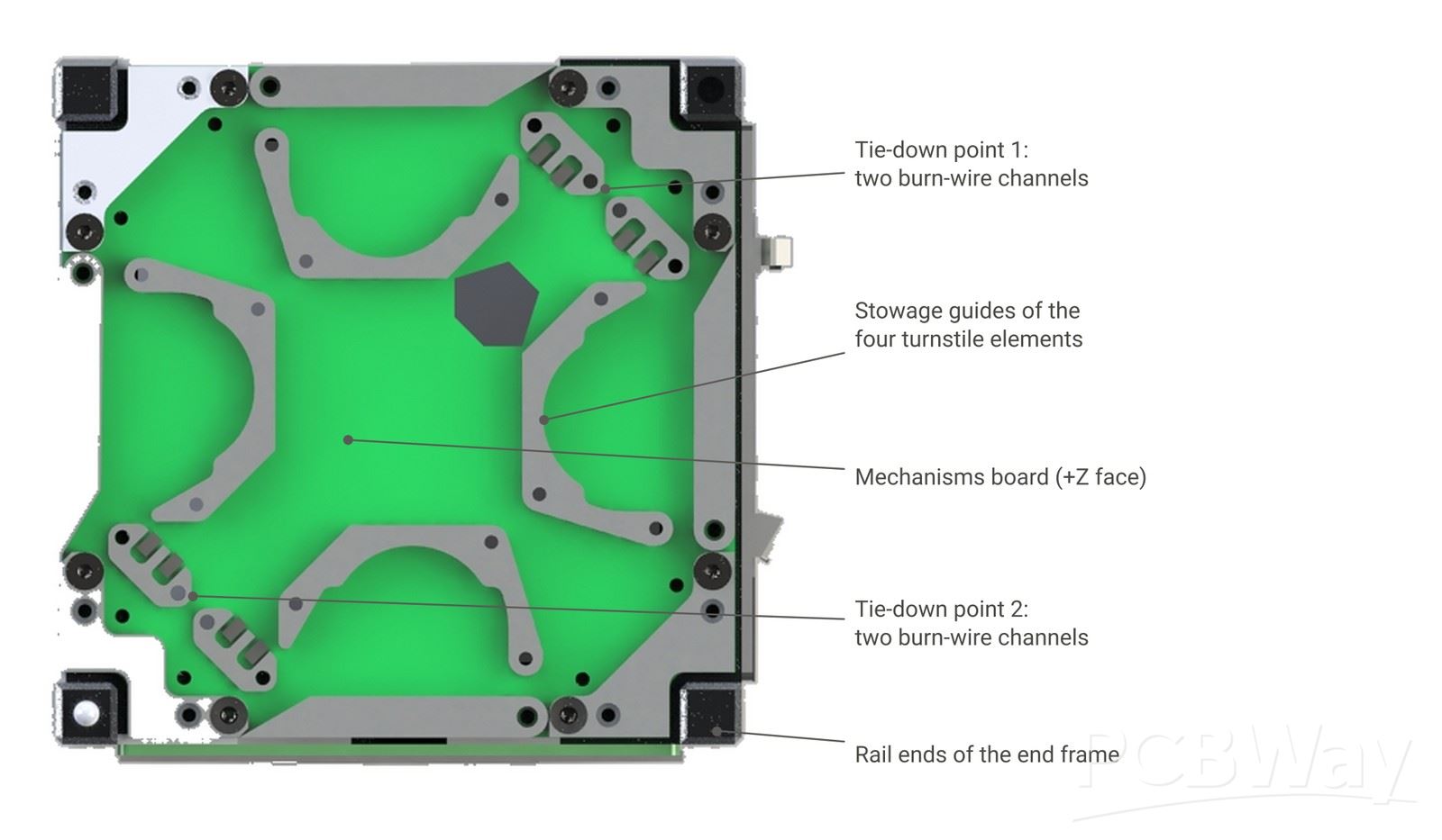
The Mechanisms board on the top face holds the four nitinol elements of the UHF turnstile antenna. They are tied down with UHMWPE line and released by heating 1206 resistors, with two independent channels per tie-down point. A lumped-element phasing network on the same PCB feeds the elements in quadrature for circular polarisation.
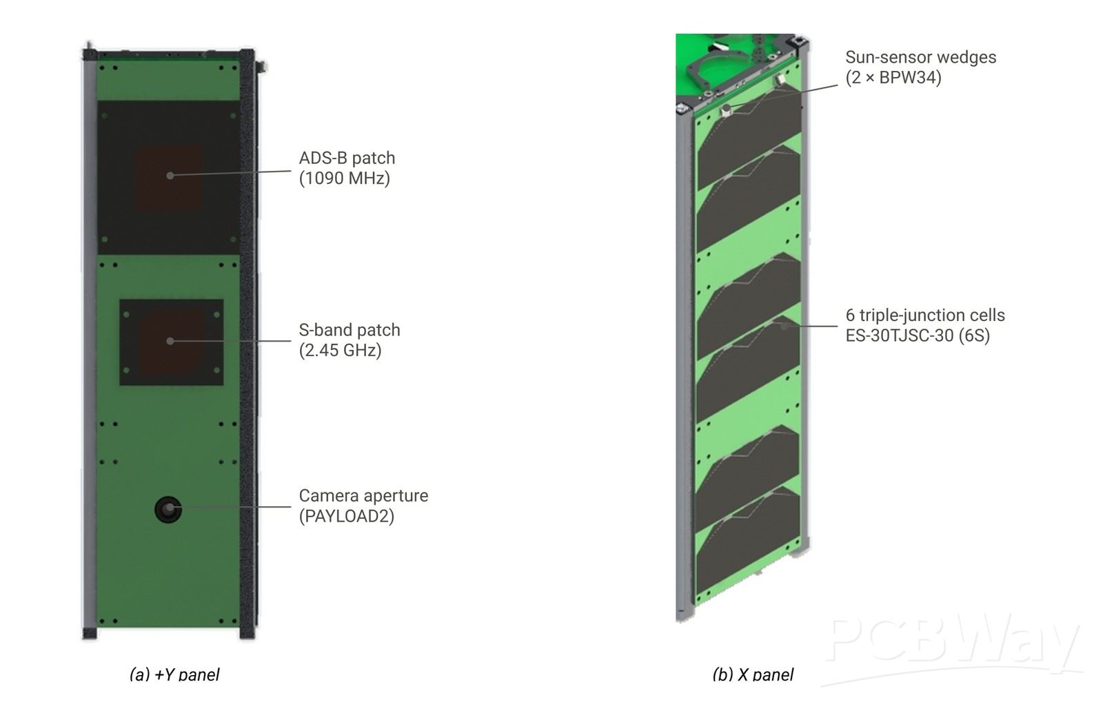
The four side panels are PCBs as well. The ±X panels carry the solar strings; the +Y panel carries the ADS-B patch antenna, the S-band patch antenna and the camera aperture; the −Y panel carries the GNSS antenna. Every panel has two photodiodes on 30° wedges for the sun sensor and a TMP117 temperature sensor.
- TESTED LIKE A REAL SATELLITE
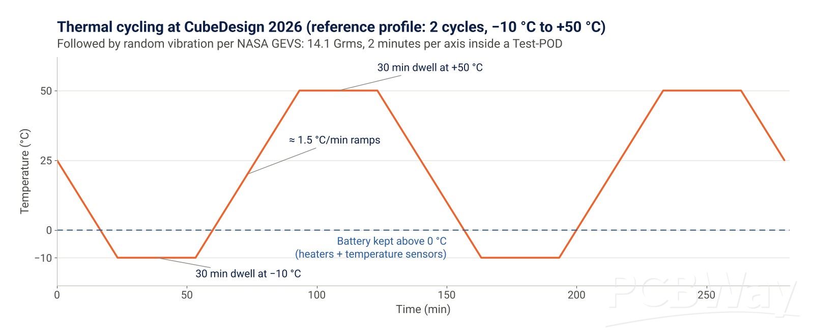
After the mission tests, CubeDesign offers optional environmental tests that our team has never had access to in Peru: thermal cycling between −10 °C and +50 °C with the satellite running, and random vibration at 14.1 Grms (NASA GEVS profile) for two minutes per axis inside a Test-POD. Surviving them multiplies the mission score by 1.4, and they are the ultimate test for every solder joint and via on our boards. Before travelling, we validate the attitude control on our own single-axis test bench in Lima, where the satellite hangs from a surveying tripod on a ball-bearing swivel.
# WORDS TO PCBWAY
- HOW PCBWAY CAN HELP US
Our first prototype boards are on their way to the laboratory, and we will test them one by one as they arrive. What we learn will go into the board set for the competition model: the flight-representative satellite that will travel to Argentina and face the thermal and vibration tests. We ask PCBWay to sponsor the fabrication of that board set and, if possible, to support the assembly of the boards with fine-pitch parts.
- Standard PCB fabrication: 11 designs (8 stack boards, the Mechanisms board and 2 side-panel designs), 5 pieces each, FR4 1.6 mm.
- RF PCB fabrication (Antennas): Custom antenna designs manufactured on Rogers high-frequency material to ensure optimal signal integrity and RF performance for our satellite communications.
- PCB assembly (student discount): Two units of each stack board, with LQFP-64 and LQFP-100 parts at 0.5 mm pitch and QFN and LGA packages.
As a student team, budget and lead time are our biggest constraints. PCBWay quality and speed would let us spend our limited resources on testing and on getting the team to the competition.
- WHAT PCBWAY GETS IN RETURN
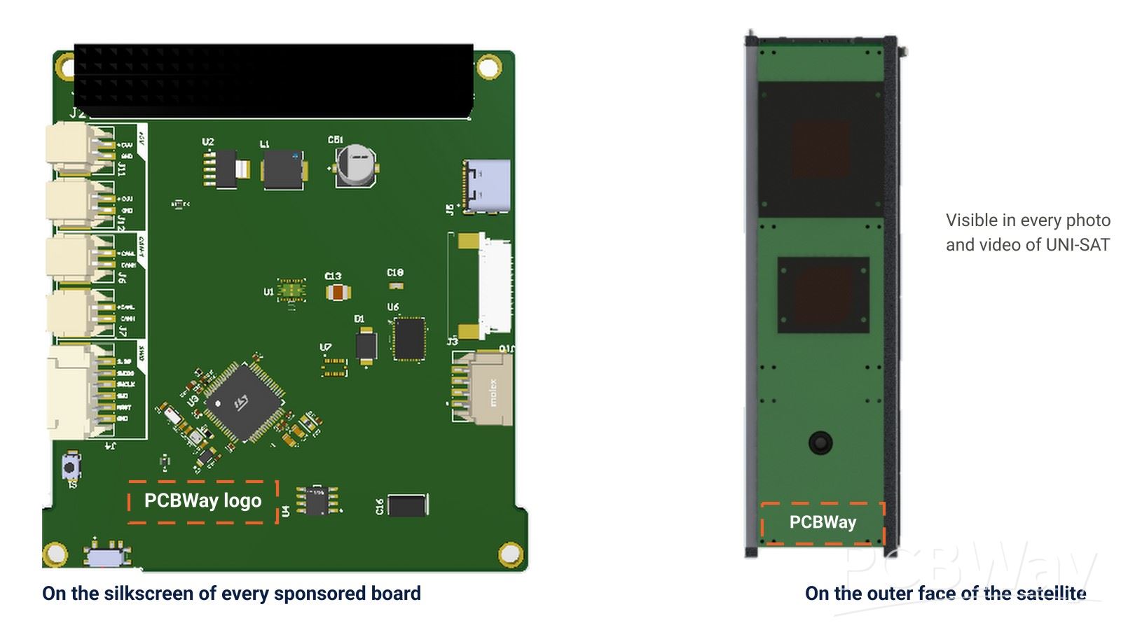
The PCBWay logo on the silkscreen of every sponsored board and on the outer +Y panel of the satellite.
An official sponsor announcement and progress posts on our social networks, tagging PCBWay.
Videos of the unboxing, assembly and testing of the PCBWay boards.
The PCBWay logo on our team shirts and banner at CubeDesign 2026, and an acknowledgement in our documentation and final presentation to the jury.
A test report on this page: how the PCBWay boards performed in bench tests, thermal cycling and vibration, with photos.
Thank you for reading about UNI-SAT. With the support of PCBWay, boards designed by Peruvian students will be tested like real space hardware.
Thank you for reading about UNI-SAT. With the support of PCBWay, boards designed by Peruvian students will be tested like real space hardware.
- Comments(0)
- Likes(1)
 More by Juan Salvador Palacios Bett
-
 UNI-SAT 3U CubeSat – Tracking Aircraft Beyond Radar Coverage
WHO I AMMy name is Juan Salvador Palacios Bett and I lead UNI-SAT, the satellite team of the Univers...
-
 UNI-SAT: Nanosatellite Flight Hardware for CubeDesign
WHO I AM My name is Juan Salvador Palacios Bett, a Mechatronics Engineering graduate from UNI and th...