


A simple transistor based electronic siren
For some time, hobbyists have relied on dedicated sound generator ICs, such as the UM3561, UM3562 to build compact alarm and siren circuits. Unfortunately, this device is becoming increasingly difficult to find in the market. The manufacturer of the chip, United Microelectronics Corporation (UMC), is still around. However, they are no longer producing the UM3561 or UM3562. As part of a fun experiment, I decided to design a replacement circuit using only discrete transistors and passive components. This avoids the need for specialized ICs altogether. The result is a simple yet effective transistor-based siren. It can reproduce the familiar rising and falling alarm effects typically associated with police cars, fire trucks, or ambulances.

The design philosophy behind this project was straightforward: recreate the functionality of the classic two-timer based siren circuit (NE556/NE555 pair), but instead of timers or sound generator ICs, use only transistors in a multivibrator and modulation arrangement. By carefully selecting resistor and capacitor values, we were able to replicate the frequency modulation effect that gives sirens their distinctive sweeping tone.
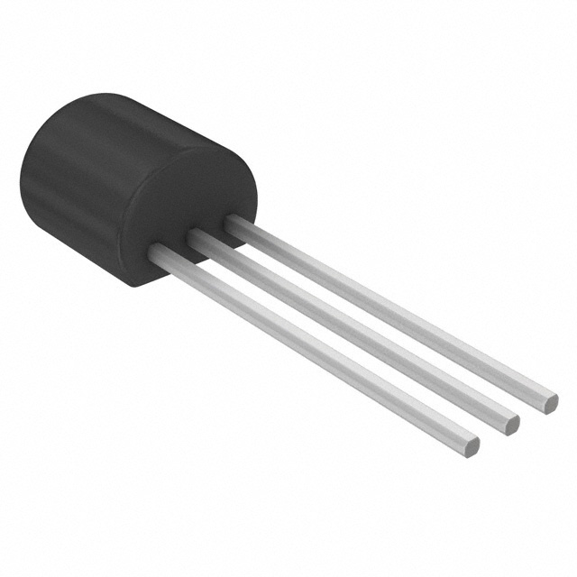
The circuit of this siren can be divided into three functional sections: the LF oscillator section, built around Q1 (BC548) and Q4 (BC558), which generates a slow modulation waveform. The rate of this oscillator, which controls how fast the siren "sweeps" up and down, can be adjusted via the 500k trim-pot (RV1). Capacitors C2 and C6, along with resistors R7 and R8, shape this low-frequency oscillation.
The next most crucial section is the audio frequency oscillator. Built around Q3 (BC558), this section is responsible for generating the actual audio tone. The output frequency is determined by the capacitor selected through jumper J1. By switching between C1, C3, and C5, different frequency ranges can be chosen, producing distinct siren effects. This is conceptually similar to selecting different alarm sound profiles on the UM3561.

The final section amplifies the modulated audio signal and drives a small speaker (16Ω - 32Ω). Diodes D1 and D2 provide bias stabilization for the push-pull transistor stage. This improves linearity and reduces distortion. The coupling capacitor C4 ensures that DC is blocked while allowing the audio signal to pass into the speaker.
This circuit is designed to operate from a 6V to 12V DC power source. The recommended supply voltage is 9V. The output frequency of this siren is heavily dependent on the supply voltage. Therefore, to produce stable output, this circuit needs a regulated "clean" DC power source.
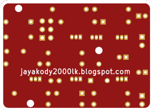
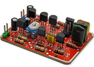
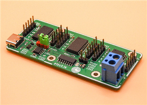
To make the project more accessible, we designed a dedicated PCB for this circuit. The board is compact and uses commonly available through-hole type components. For convenience, standard 2.54mm pin headers are provided for the speaker, power input, and jumper settings.
To complement this project, we also created a short video showing the assembly process and testing of the siren. The demonstration highlights how the different jumper settings produce distinct alarm effects, and how adjusting the rate control potentiometer changes the siren’s sweep speed.
All the resources of this project, including KiCAD design files and schematics, are available to download at https://github.com/dilshan/simple-electronic-siren.
A simple transistor based electronic siren
*PCBWay community is a sharing platform. We are not responsible for any design issues and parameter issues (board thickness, surface finish, etc.) you choose.


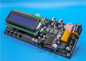
Raspberry Pi 5 7 Inch Touch Screen IPS 1024x600 HD LCD HDMI-compatible Display for RPI 4B 3B+ OPI 5 AIDA64 PC Secondary Screen(Without Speaker)
BUY NOW


- Comments(0)
- Likes(0)
More by Dilshan Jayakody
-
 A simple transistor based electronic siren
For some time, hobbyists have relied on dedicated sound generator ICs, such as the UM3561, UM3562 to...
A simple transistor based electronic siren
For some time, hobbyists have relied on dedicated sound generator ICs, such as the UM3561, UM3562 to...
-
 Analog pink noise generator
Pink noise is an essential tool in audio testing, widely used for analyzing speaker systems, room ac...
Analog pink noise generator
Pink noise is an essential tool in audio testing, widely used for analyzing speaker systems, room ac...
-
 ZZRX-40 Receiver build
I found the ZZRX-40 receiver while going through some old issues of QEX magazine. Designed by Craig ...
ZZRX-40 Receiver build
I found the ZZRX-40 receiver while going through some old issues of QEX magazine. Designed by Craig ...
-
 Arduino Mini Amplifier
The Arduino Mini Amplifier is a compact audio system that merges vintage analog and modern digital c...
Arduino Mini Amplifier
The Arduino Mini Amplifier is a compact audio system that merges vintage analog and modern digital c...
-
 24-channel USB high-voltage driver
When it comes to automation and control systems, there's often a need for multiple digitally control...
24-channel USB high-voltage driver
When it comes to automation and control systems, there's often a need for multiple digitally control...
-
 Echo Generator for Microphones
This project is about a single-channel microphone echo generator circuit. This circuit builds around...
Echo Generator for Microphones
This project is about a single-channel microphone echo generator circuit. This circuit builds around...
-
 Universal HD44780 LCD interface
YALI (Yet Another LCD Interface) is an open-source project to provide a universal interface to drive...
Universal HD44780 LCD interface
YALI (Yet Another LCD Interface) is an open-source project to provide a universal interface to drive...
-
 6-channel stereo speaker selector
This project is a DIY six-channel stereo speaker selector based on STC15W201 MCU. The purpose of thi...
6-channel stereo speaker selector
This project is a DIY six-channel stereo speaker selector based on STC15W201 MCU. The purpose of thi...
-
 5.1 channel analog audio processor
In this project, we developed a 5.1-channel analog audio processor using PT2322 IC. PT2322 is an ine...
5.1 channel analog audio processor
In this project, we developed a 5.1-channel analog audio processor using PT2322 IC. PT2322 is an ine...
-
 StarPointer - virtual electronic finderscope
StarPointer is a virtual electronic finderscope for astronomical telescopes. This device works with ...
StarPointer - virtual electronic finderscope
StarPointer is a virtual electronic finderscope for astronomical telescopes. This device works with ...
-
 Narrowband FM receiver for 2-meter band
This project is about MC3362 and ADF4351 based modularized, 2-meter narrow band FM receiver. In this...
Narrowband FM receiver for 2-meter band
This project is about MC3362 and ADF4351 based modularized, 2-meter narrow band FM receiver. In this...
-
 5.1 channel audio preamplifier
This project introduces a digitally controlled 5.1 channel audio preamplifier system. This amplifier...
5.1 channel audio preamplifier
This project introduces a digitally controlled 5.1 channel audio preamplifier system. This amplifier...
-
 NTP based digital clock panel
This project introduces an open-source, ATmega328 based, configurable NTP clock with a 2.3-inch, 7-s...
NTP based digital clock panel
This project introduces an open-source, ATmega328 based, configurable NTP clock with a 2.3-inch, 7-s...
-
 AVR High Voltage Programmer 2
AVR-HV2 is Arduino based high voltage parallel programmer for AVR microcontrollers. This programmer ...
AVR High Voltage Programmer 2
AVR-HV2 is Arduino based high voltage parallel programmer for AVR microcontrollers. This programmer ...
-
Programmable Mist Maker - XIAO / QT PY Extension
240 0 0 -
RadioHAT - Raspberry Pi radio development platform
262 0 1 -
-
-
-
-
ARPS-2 – Arduino-Compatible Robot Project Shield for Arduino UNO
2818 0 6 -
A Compact Charging Breakout Board For Waveshare ESP32-C3
3323 3 8 -
AI-driven LoRa & LLM-enabled Kiosk & Food Delivery System
3617 2 2


