


|
|
DRV8212DRLR |
x 1 | |
|
|
XL-1005UOCXINGLIGHT
|
x 1 | |
|
|
XL-1005UBCXINGLIGHT
|
x 1 | |
|
|
RC0201JR-07510RLYAGEO
|
x 2 | |
|
|
CL03A104KA3NNNCSamsung
|
x 1 | |
|
|
CL05A475MO5NUNCSamsung
|
x 1 | |
|
|
D12V0L1B2LP-7B |
x 1 |

|
KiCad 8.0KiCad
|
TinyDRV - a MUST-HAVE add-on for N20 DC motors
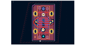
N20 motor brushes are hard to solder, and you always need an external motor driver which takes up a lot of space and is often inefficient, like the L298N or TB6612FNG. The TinyDRV is here to solve both of these problems. It integrates a tiny 4 amp, 2 to 10V motor driver, ESD protection, and LED indicators to tell you which way and how fast the motor is going. If you don't want the LED indicators for low-power consumption (which this thing is great at, by the way), you can just cut the solder jumper at the back of the board. For robots like 150g antweights, this means that an all-in-one controller would only require a 4-pin connection to each TinyDRV + N20 motor assembly, with significant space savings since the motor drive circuitry is off the main control board. However, this would require a custom all-in-one controller made to break out the standard IN1/IN2 connection to each motor driver. For line followers and sumo robots, which already have custom code running, it would be much easier to implement a TinyDRV, since it can work with any MCU that outputs PWM on at least 2 channels per motor. The weight of an assembled TinyDRV PCB is ~0.2g, as far as I could tell.
The LED indicators can always be turned off by cutting a solder jumper at the back of the board before you solder it onto the N20 motor.
The pinout (from left to right, where the top is defined as where the wires come out) is as follows: VIN (2V - 10V), IN1, IN2, GND.
IN1 and IN2 control involves holding one control input at ground, and applying a PWM signal to the other for speed control. When both IN1 and IN2 are pulled to ground, the motor outputs are essentially disconnected and the motor driver chip enters a low-power sleep mode. When both IN1 and IN2 are pulled high, we call it 'brake' mode, where the motor's energy slowly decays into ground. If IN2 is high and IN1 is low, OUT2 (right side) is high and OUT1 (left side) is low, and vice versa. This motor driver is to only be driven with PWM or digital signals (1.8V, 3.3V, 5V logic signal compatible). Read the DRV8212 datasheet for more details: https://www.ti.com/lit/ds/symlink/drv8212.pdf?HQS=dis-dk-null-digikeymode-dsf-pf-null-wwe&ts=1733100409496 or contact me on discord @_h1tec for any questions. You are free to buy this board and sell it to others in your community, in fact, please do, as long as you go through PCBWay projects :).
This board should also work (not tested, but all dimension diagrams point to this being possible) with N10, N30, N40, and N50 motors, as long as the current requirements of the motor are below around 4 amps at stall (I used it with a motor that stalls at 4.3 amps though, but it was a 3.6V motor).
Note:
Ordering parameters (panels of 4):
- Panel by PCBWay
Panel requirements:
Breakaway rail: yes
Panel 1*4, joined at flat edges of board, breakaway rail width 10mm, total 5 panels = total 20 individual boards (modify for your liking, for example, total 20 panels = total 80 individual boards)
Route process: Panel as PCBWay prefer
X-Out Allowance in panel: Accept
- 12 x 98mm
- 4 layers (for heat dissipation)
- Layer names from top to bottom are F.Cu In1.Cu In2.Cu B.Cu in the gerber file
- 1mm thickness
- 5mil clearance / track width
- 0.25mm min hole size
- I love purple soldermask, but you can get whatever you want lol
- Surface finish: I normally go with HASL lead-free
- Tenting vias
- 1oz Cu Finished and Inner
- Remove product number: Yes
- No customized services or advanced options
- Assembly sides: Top side only
- Sensitive components? No
- Alternative components? No
- No other parameters (PCBWay will do this for you in the final quote)
- No customised services and advanced options
Contact me on discord @_h1tec for help ordering or anything like that :)
TinyDRV - a MUST-HAVE add-on for N20 DC motors
*PCBWay community is a sharing platform. We are not responsible for any design issues and parameter issues (board thickness, surface finish, etc.) you choose.


Raspberry Pi 5 7 Inch Touch Screen IPS 1024x600 HD LCD HDMI-compatible Display for RPI 4B 3B+ OPI 5 AIDA64 PC Secondary Screen(Without Speaker)
BUY NOW


- Comments(11)
- Likes(31)
- 2 USER VOTES
- YOUR VOTE 0.00 0.00

-
10design
-
10usability
-
10creativity
-
10content
-
10design
-
10usability
-
10creativity
-
10content
More by Rain Haase
-
 PCBWay 11th anniversary badge project
Fun little light up badge project. Uses comparators, an RC circuit, and a 555 timer to make a loopin...
PCBWay 11th anniversary badge project
Fun little light up badge project. Uses comparators, an RC circuit, and a 555 timer to make a loopin...
-
 TinyDRV - a MUST-HAVE add-on for N20 DC motors
N20 motor brushes are hard to solder, and you always need an external motor driver which takes up a ...
TinyDRV - a MUST-HAVE add-on for N20 DC motors
N20 motor brushes are hard to solder, and you always need an external motor driver which takes up a ...
-
 USB-C breakout PCB
 device
USB-C breakout PCB
USB-C breakout PCB device
-
 Parent PCB
 for ESP32 board
Parent PCB
Parent PCB for ESP32 board
-
 Motor driver
 board 1
Motor driver
Motor driver board 1
-
 VL53L7CX ultra-mini breakout
A super tiny breakout for VL53L7CX with the bare minimum functions to get it running - just the I2C ...
VL53L7CX ultra-mini breakout
A super tiny breakout for VL53L7CX with the bare minimum functions to get it running - just the I2C ...
-
 Custom Line Sensor in KiCad for PID line follower
I'm currently making an advanced line follower from scratch, which will be following a 7.5mm black l...
Custom Line Sensor in KiCad for PID line follower
I'm currently making an advanced line follower from scratch, which will be following a 7.5mm black l...
-
-
ARPS-2 – Arduino-Compatible Robot Project Shield for Arduino UNO
2511 0 5 -
A Compact Charging Breakout Board For Waveshare ESP32-C3
2963 3 8 -
AI-driven LoRa & LLM-enabled Kiosk & Food Delivery System
3174 2 1 -
-
-
-
ESP32-C3 BLE Keyboard - Battery Powered with USB-C Charging
3233 0 2


