


|
KiCad 9.0 |
|

|
arduino IDEArduino
|
ESPBoy powered by 18650 battery
ESPBoy powered by 18650 battery
Start
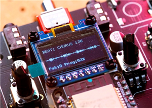
Making game consoles is always fun for electronics hobbyists.
The original circuit was made open by the ESPBoy community, so it’s easy for anyone to build.
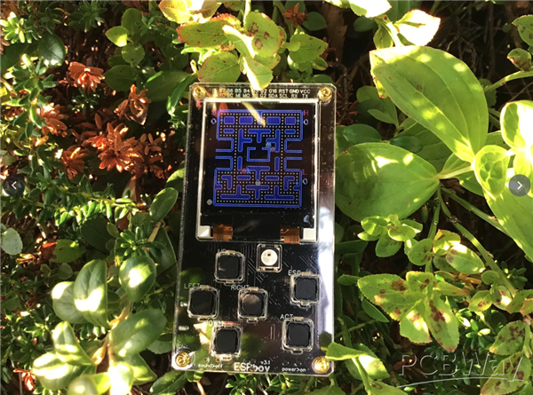
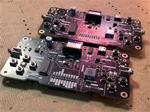
I started out by ordering a PCB based on the published design, soldering the components myself, and assembling the whole thing.
Of course, it worked—but I felt that the component layout could be a bit cleaner.
So I thought since I’m doing this for fun anyway, why not add a few personal touches?
One thing I really wanted was to be able to charge the battery via USB, instead of replacing it every time.
That meant I needed to add a charging circuit.
Also, if I’m going to include USB, I thought it would be great if the system could automatically switch between USB power and battery power, without needing a physical switch—drawing power from USB when connected, and falling back to the battery when unplugged.
Lastly, instead of using multiple separate modules, I wanted to integrate all the features into a single PCB to make the whole system as compact and neat as possible.
Circuit design
To implement the features I mentioned earlier, each of them requires its own dedicated circuit.
In this section, we’ll take a closer look at each of these circuits.
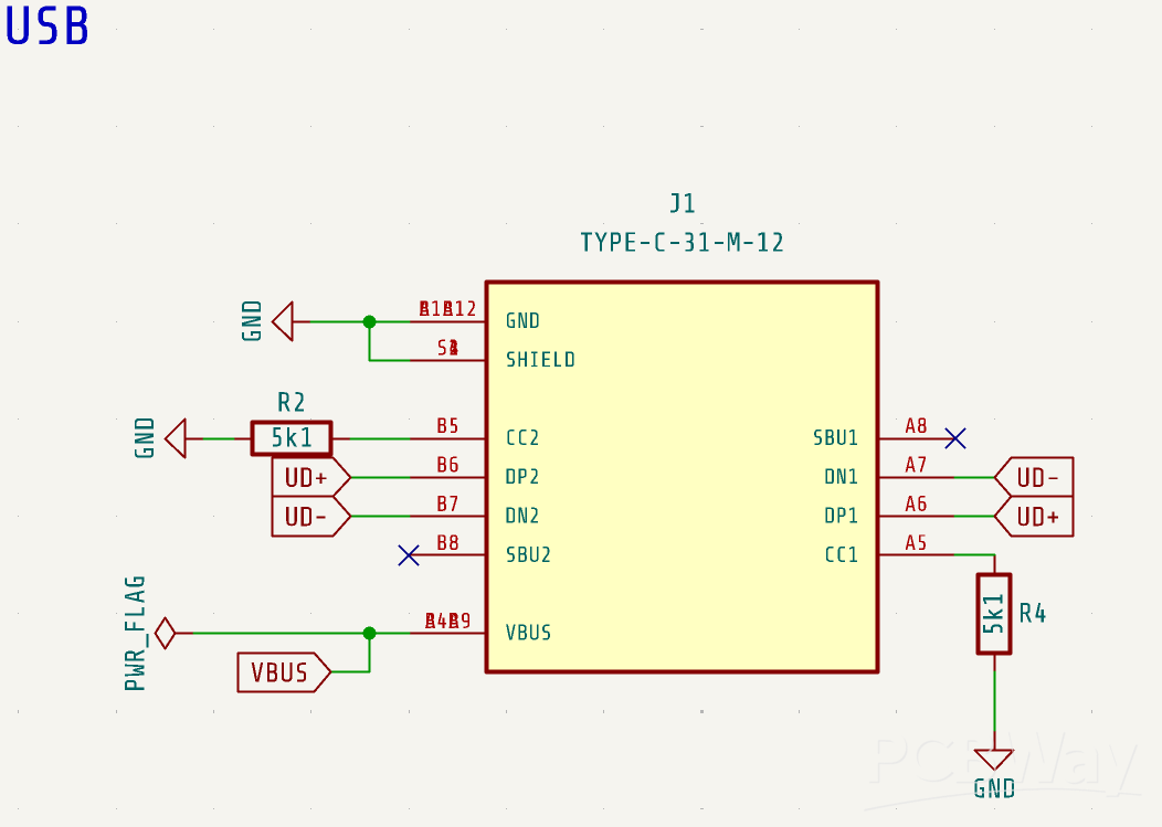
USB-UART circuit
A USB connector is essential—it’s used for both supplying power and uploading programs. A 5.1 kΩ resistor is included to ensure proper 5 V power detection.
Next in line is the CH340C, a commonly used USB-to-UART bridge IC.
While the D5 and D6 LEDs are not strictly necessary, they make it easy—and a bit fun—to visually confirm RX and TX activity during program uploads.
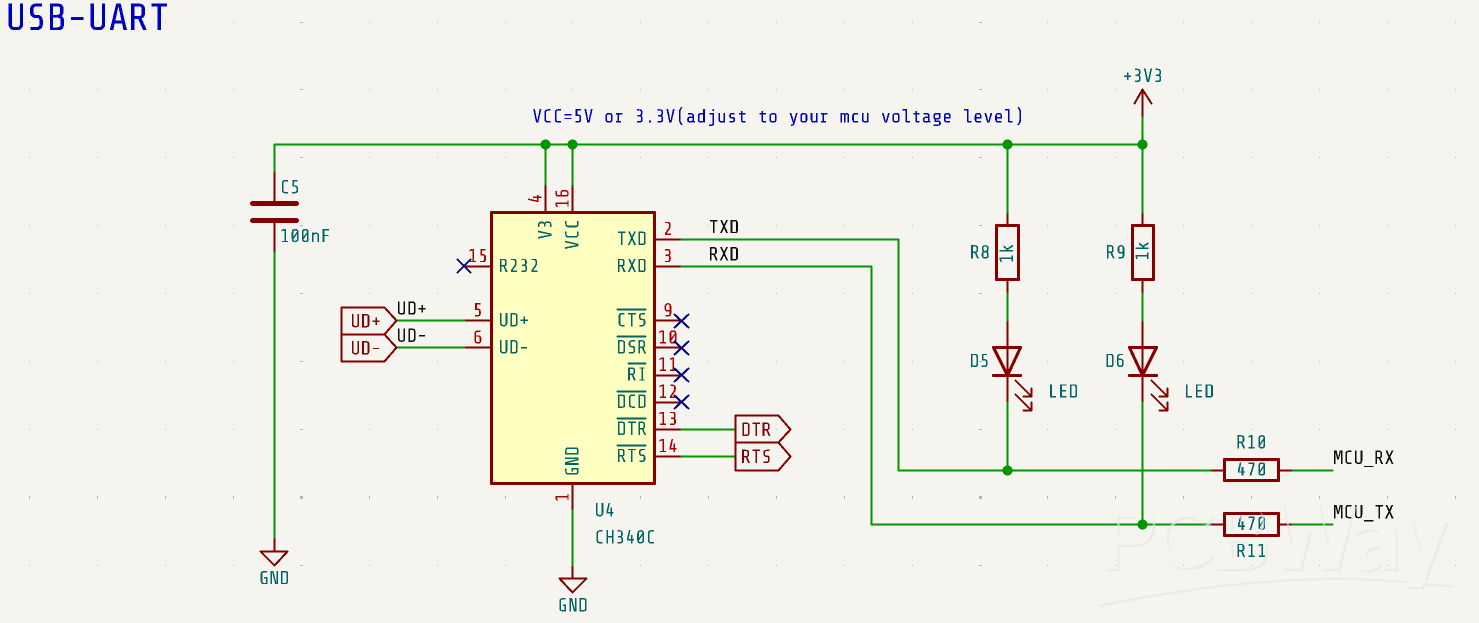
Since the CH340C has a built-in crystal oscillator, the surrounding circuitry can remain quite simple.
Just be sure to double-check the TX and RX connections: CH340C’s TX should go to the MCU’s RX, and vice versa. This is a common place where mistakes happen—even though it looks simple, it's easy to mix them up.
AutoFlash
Auto-flash circuits often use a combination of two discrete transistors and several resistors, but in this design, we achieve the same functionality using just a single UMH3N—dramatically saving board space.
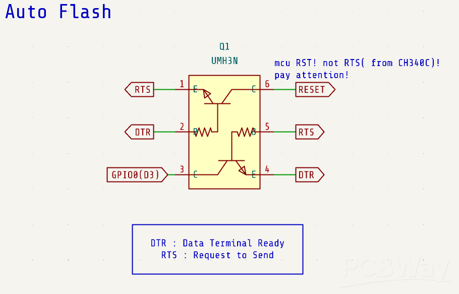
The UMH3N conveniently integrates two transistors along with built-in base and base-emitter resistors, reducing the need for external components.
It’s an impressively clever part—credit to whoever came up with such a smart idea!
ESP-WROOM-02
In this design, instead of using a D1 mini module, I chose to use the ESP-WROOM-02.
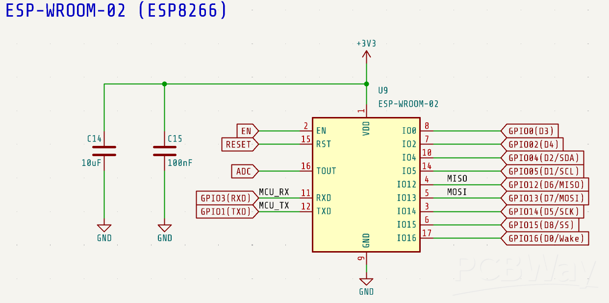
Although it’s still based on the same ESP8266 core, so compatibility isn’t an issue, you do need to pay attention to the pin assignments and double-check your wiring accordingly.
As you can see here, I’ve labeled each pin with its commonly used function as well, to make the layout easier to read at a glance.
5V Power
Next is the power supply section.
When using USB, 5V is drawn from the USB connector to power the circuit.
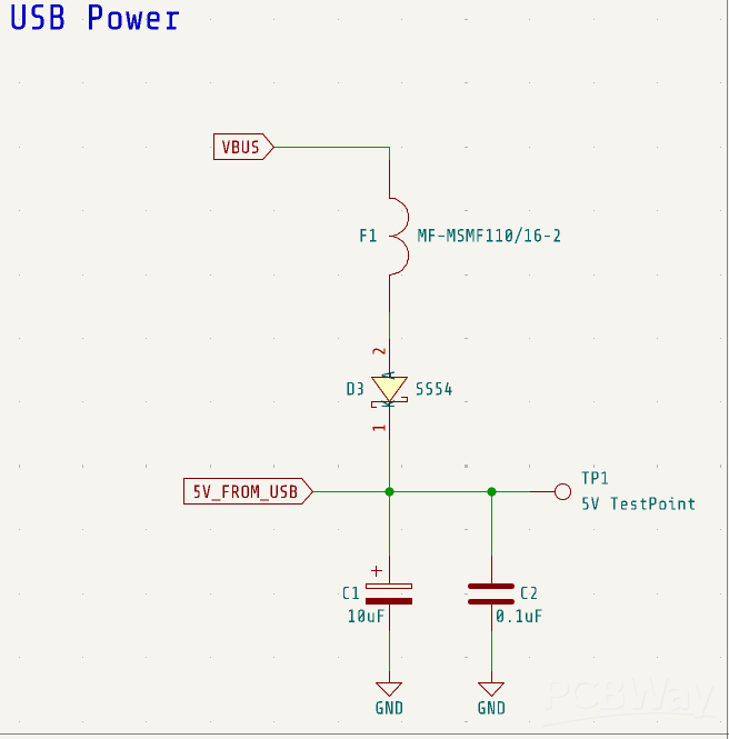
To protect the connected PC from potential damage in case of a fault—such as a short circuit or excessive current draw—I add diode D3. This diode prevents reverse current flow back into the USB power line.
Additionally, a resettable fuse is included. If the current exceeds a certain threshold, the fuse will temporarily shut off the circuit to prevent damage. Once the fault is cleared and the fuse cools down, it will automatically reset—making it a reusable and reliable protection component.
Power Supply Auto switch
We want to be able to power the circuit either from a USB source or from a battery.
Of course, it would be possible to use a manual switch to select the power source, but that approach is a bit inconvenient. So ideally, we want the system to automatically choose the appropriate power source.
That’s where this circuit comes in. It's a widely used method found on many boards.
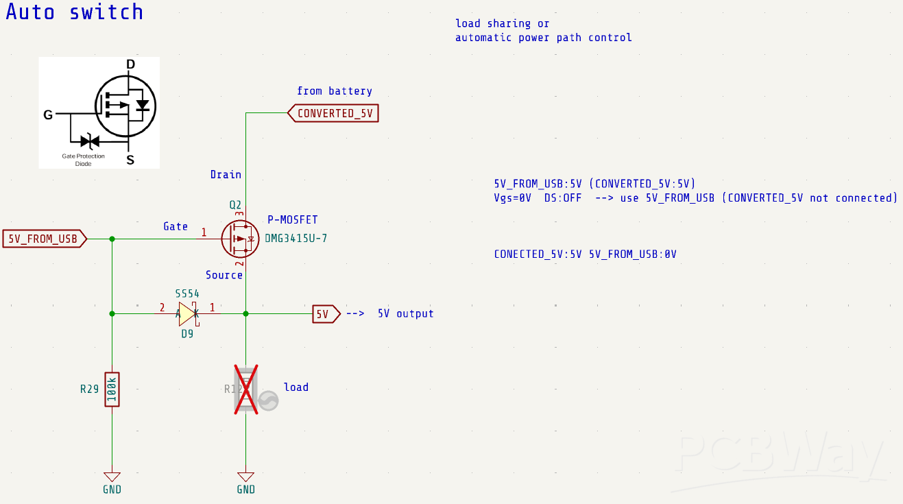
Initially, I tried a different design that was more complicated and not very elegant, but in the end, this approach turned out to be the simplest and most efficient, using the fewest components.
To put it simply, when the USB supplies 5V, the gate of the P-channel MOSFET (such as the DMG3415U-7) is also at 5V because it is connected directly to the USB 5V rail. Since the source is connected to the USB 5V through a forward-biased diode, the source is likewise at 5V. This results in a gate-source voltage (Vgs) of 0V.
As Vgs is not negative enough to turn on the P-channel MOSFET, the device remains off. Even if 5V is present at the drain (e.g., from the battery), the USB 5V takes priority and powers the output.
When the USB is disconnected, the gate is pulled to GND by a pull-down resistor (e.g., R29). In this case, the drain is supplied with 5V from the battery. In this circuit, it comes from a DC-DC converter, which I will talk about later.
Initially, the body diode of the P-MOSFET conducts a small current, allowing the output capacitor to charge gradually. As the source voltage rises, the gate-source voltage (Vgs) becomes sufficiently negative—exceeding the MOSFET’s threshold voltage in magnitude—and the MOSFET turns fully on.
This allows current to flow freely from drain to source, and the output is now powered by the battery.
This automatic power path selection circuit leverages the P-channel MOSFET’s intrinsic body diode and gate threshold characteristics to prioritize USB power when available, and seamlessly switch to battery power when USB is unavailable.
Charging circuit
The charging circuit uses the TP5400. I’ve explained the TP5400 and the overall charging circuit in a previous video, so please refer to that if you’d like more details.
DC/DC Converter
This is a DC/DC converter circuit that steps down 5V to 3.3V for the ESP8266.
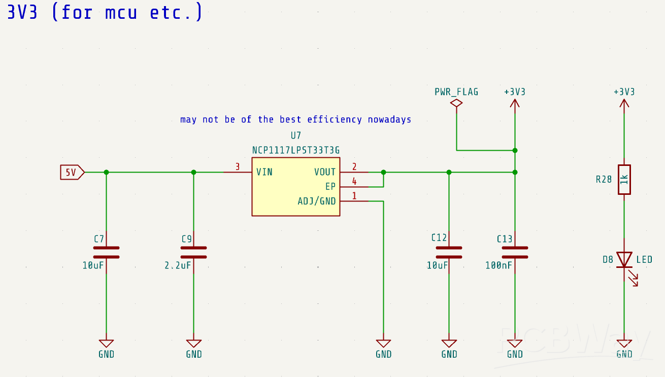
Here, we use the NCP1117, a common and widely used linear voltage regulator. Of course, you can use other voltage regulators without any issues. It might not be the most efficient choice currently available, but it works sufficiently well for this application.
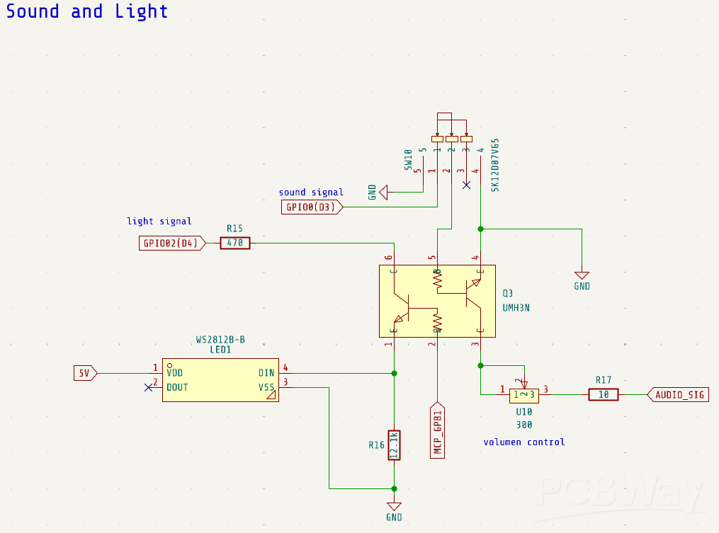
Sound and Light Control
Next, these are the circuits for controlling the RGB LED and the sound. We use the two transistors inside the UMH3N separately to control the LED and the audio output signal.
Audio Amplifier Circuit
Next to it is an audio amplifier circuit using the FM8002A, which is also employed in the Mini DFPlayer. This circuit amplifies the input analog signal and drives a speaker.
The gain of the amplifier can be adjusted by changing the values of resistors R23 and R24. In this circuit, both are set to 20kΩ, but the volume seems a bit low. Slightly increasing R24 might improve the volume.
The overall circuit configuration closely follows the recommended design from the datasheet.
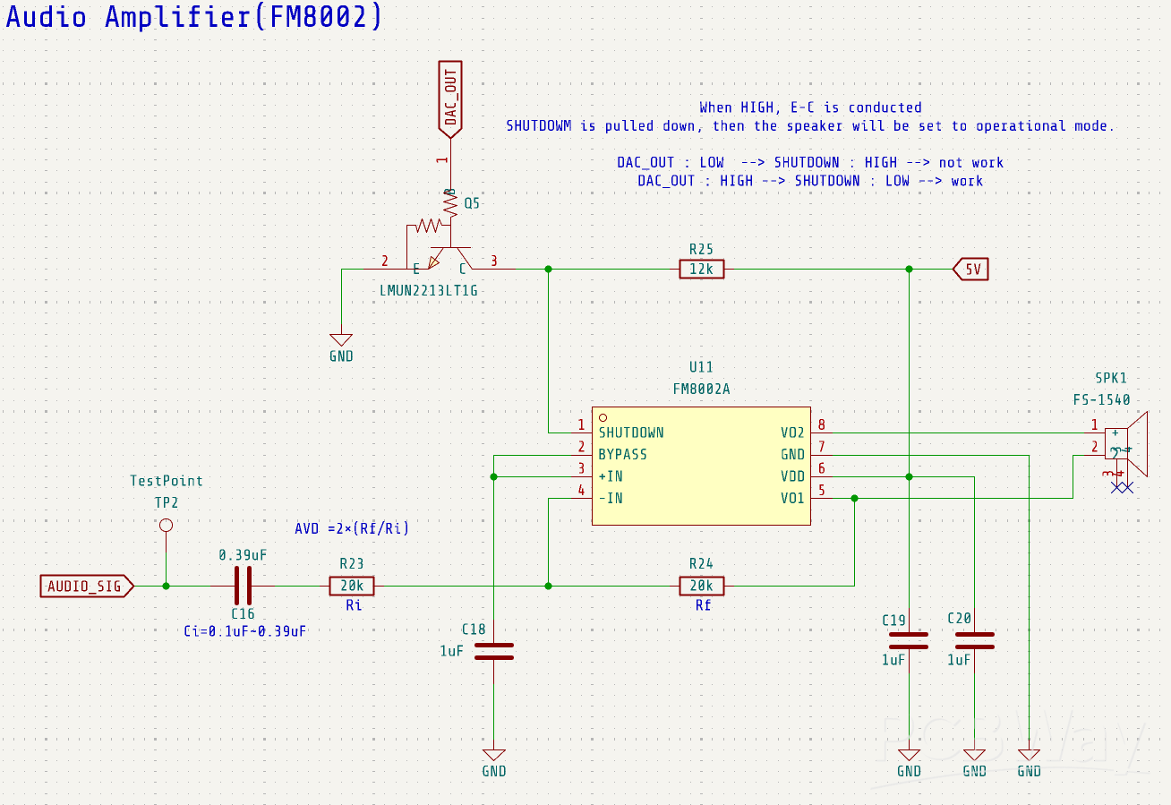
When a HIGH signal is received from DAC_OUT, transistor Q5 turns on and pulls the SHUTDOWN pin low, putting the FM8002A into operational mode.
When DAC_OUT is low, Q5 is off and its emitter-collector path is open. In this state, the SHUTDOWN pin is pulled up by resistor R25, which keeps the amplifier disabled.
This reduces current consumption to around 4.2 µA, contributing to power savings.
Although DAC_OUT is technically an analog signal, I realized after the design was completed that it's not ideal to use it directly as a digital input for Q5.
However, in practice, the signal usually stays near its minimum or maximum values (effectively LOW or HIGH), except for brief transitions.
As a result, the circuit still functions reliably in this application.
I/O Expender
Next is the I/O expander circuit. The ESPBoy uses 10 buttons, plus controls for the display, audio, RGB lighting, and more, so the available GPIO pins are somewhat limited. To expand the number of GPIOs, we use the MCP23017-E/SO.
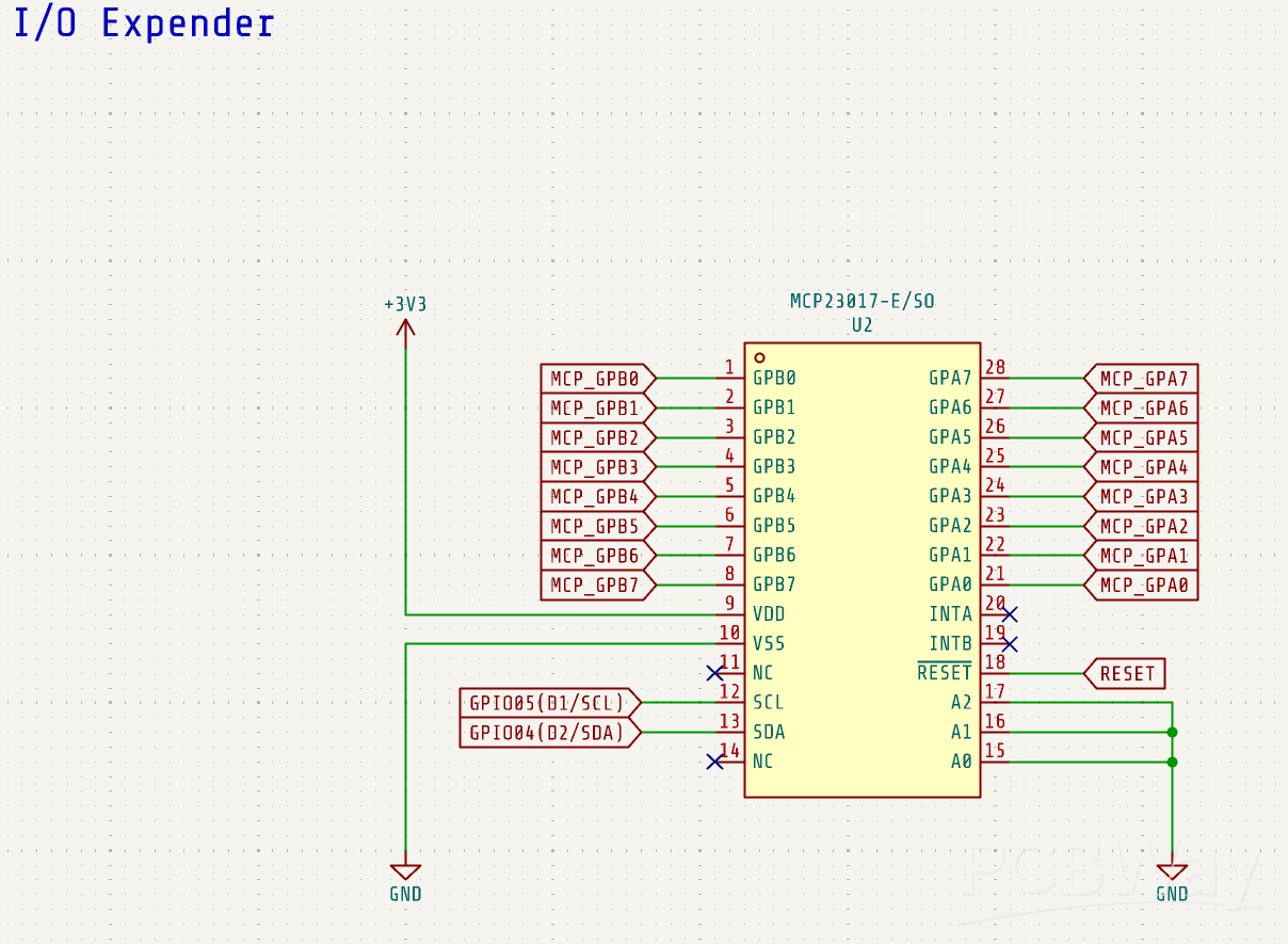
A key feature of the MCP23017 is that it communicates via the I2C interface. This allows the MCU to control many more GPIO pins using just two I2C lines: the SCL pin and the SDA pin.
By using these two pins, you can expand the GPIO count by 16 additional pins.
D/A converter
The D/A converter used in this circuit is the MCP4725A0T. It is a 12-bit digital-to-analog converter with built-in EEPROM memory. The input interface is I²C, and the output is an analog voltage.
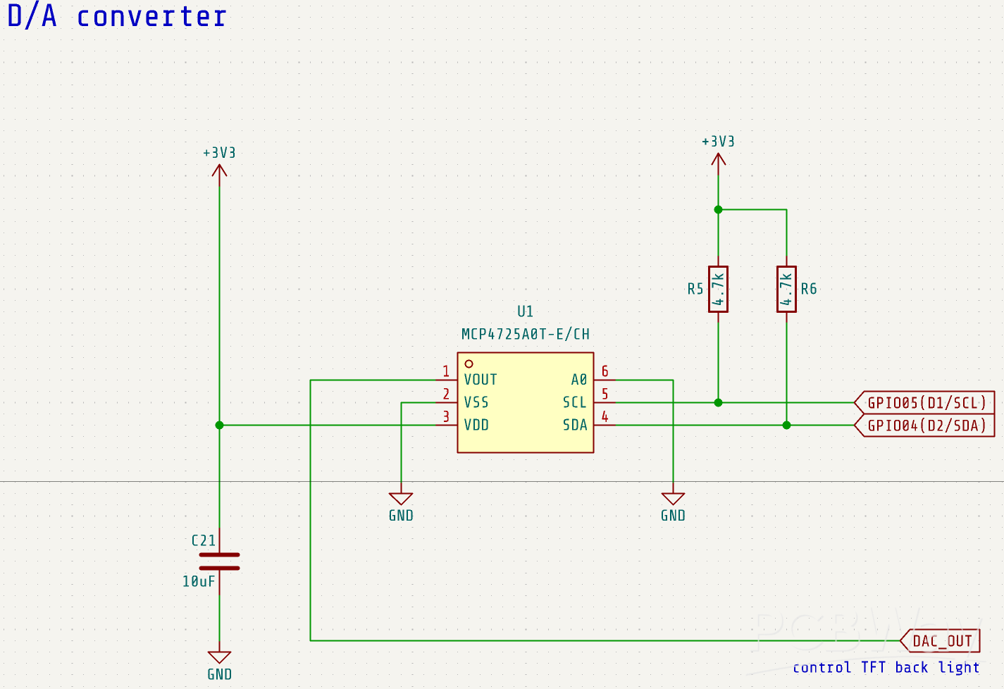
The DAC output (DAC_OUT) is used to control the brightness of the display by connecting to the BL (backlight) pin of the LED module.
Additionally, as mentioned earlier, it is also used to control the SHUTDOWN pin of the FM8002A audio amplifier, effectively acting as a switch to toggle the amplifier between operational and shutdown modes.
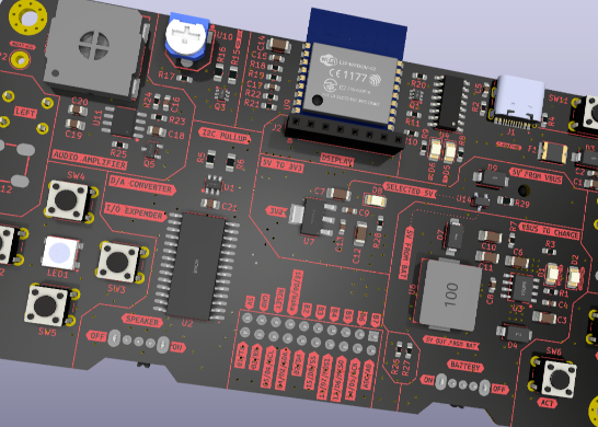
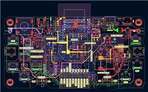
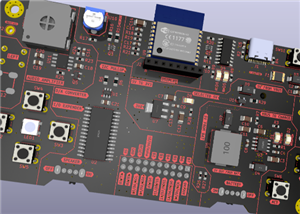
PCB design
Once the circuit schematic was ready, I moved on to designing the PCB layout.
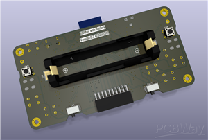
To begin with, I chose a horizontal form factor to accommodate the largest component—the 18650 battery holder.
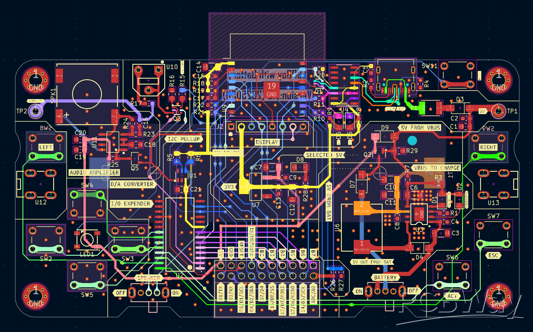
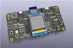
The ESP-WROOM-02 was placed at the center of the board, with its antenna extending past the edge of the PCB to improve wireless performance. Directly beneath the module, I positioned the display so that it sits approximately in the center of the board.
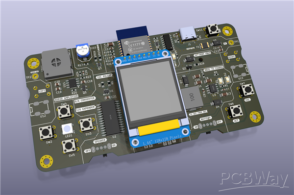
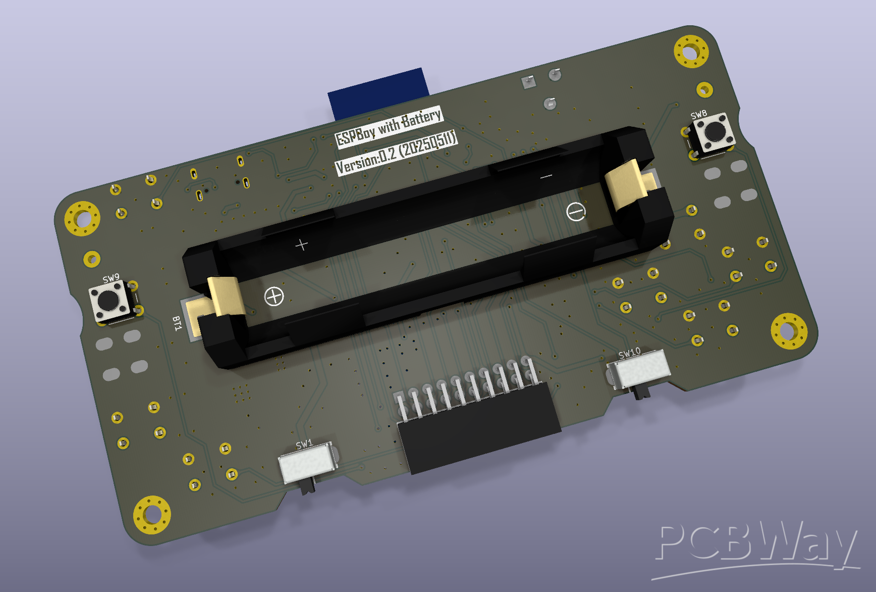
The speaker is mounted on the front side, while the battery holder is placed on the back to save space on the front side of the PCB.
For the controls, the directional buttons (up, down, left, right) are arranged on the left side, and the ACT and ESC buttons are placed on the right. I put the RGB LED at the center of the directional button cluster—it can be quite bright during operation, but it's not a big issue.
The speaker on/off switch and the main power switch are also located on the back side, keeping the front layout clean and uncluttered.
I also placed the two extra buttons labeled LEFT and RIGHT on the back, reserved for special operations I guess. Although they’re not used at the moment, they could be useful depending on the application.
GitHub Repo
coming soon ...
ESPBoy powered by 18650 battery
*PCBWay community is a sharing platform. We are not responsible for any design issues and parameter issues (board thickness, surface finish, etc.) you choose.


Raspberry Pi 5 7 Inch Touch Screen IPS 1024x600 HD LCD HDMI-compatible Display for RPI 4B 3B+ OPI 5 AIDA64 PC Secondary Screen(Without Speaker)
BUY NOW


- Comments(0)
- Likes(1)
More by Ken Kawashima
-
 ESP32_walkie_talkie_v2
ESP32 walkie-talkie, you kid will love it!more details to come!All the details can be found on GitHu...
ESP32_walkie_talkie_v2
ESP32 walkie-talkie, you kid will love it!more details to come!All the details can be found on GitHu...
-
 ESP32-Mozzi-synthesizer
A tiny synthesizer built with an ESP32, running the Mozzi library. It’s simple, compact, and powerfu...
ESP32-Mozzi-synthesizer
A tiny synthesizer built with an ESP32, running the Mozzi library. It’s simple, compact, and powerfu...
-
 ESPBoy powered by 18650 battery
StartMaking game consoles is always fun for electronics hobbyists.Th...
ESPBoy powered by 18650 battery
ESPBoy powered by 18650 batteryStartMaking game consoles is always fun for electronics hobbyists.Th...
-
 PCBWay 11th Anniversary Badge
A beautiful badge for PCBWay 11th anniversary!Graphic design and conceptby Guiye Perez BongiovanniIt...
PCBWay 11th Anniversary Badge
A beautiful badge for PCBWay 11th anniversary!Graphic design and conceptby Guiye Perez BongiovanniIt...
-
Programmable Mist Maker - XIAO / QT PY Extension
431 0 0 -
RadioHAT - Raspberry Pi radio development platform
338 0 1 -
-
-
-
-
ARPS-2 – Arduino-Compatible Robot Project Shield for Arduino UNO
2887 0 6 -
A Compact Charging Breakout Board For Waveshare ESP32-C3
3386 3 8 -
AI-driven LoRa & LLM-enabled Kiosk & Food Delivery System
3716 2 2


