

|
|
ESP-01S |
x 1 |

|
KiCADKicad
|
|

|
arduino IDEArduino
|
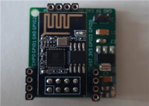
ESP01S board
Hi PCBWayers!
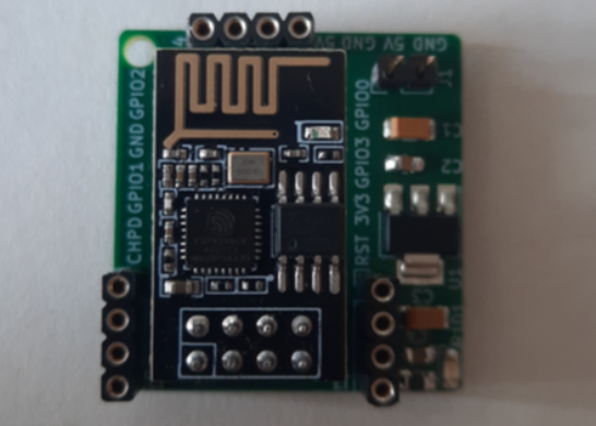
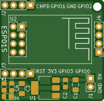
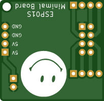
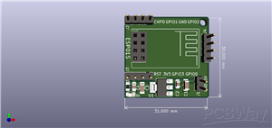
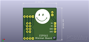
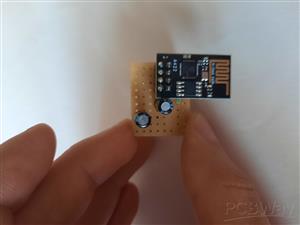
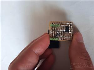
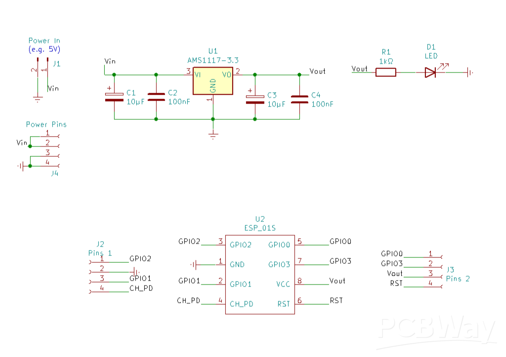
While in the previous project I showed you a small PCB for the ESP01, this version is for the ESP01S.
It is very important to go through the description to understand the differences and how to program the ESP01S module.
- Add the ESP 01/01S board to the Arduino IDE (if it doesn't already exist) by entering the link in the indicated field (Arduino IDE → File → Preferences): http://arduino.esp8266.com/stable/package_esp8266com_index.json
Put a comma (,) between the others, if there are others (this is my case). Now we have the path needed to install the board.
- Open Tools → Board → Boards Manager and search for "ESP8266", then install the version created by ESP8266 Community.
Now we need to know that there are physical differences between ESP01 and ESP01S. On the ESP01 the red LED is for power signaling and the blue LED is the "built-in" one that can be controlled by program. On the ESP01S we have a blue LED (built-in) that can be controlled by program.
But the pinout is the same:
The diagram below shows how to program the ESP01S using FTDI. Be careful, put the jumper on 3.3V at FTDI, the ESP 01/01S board works at 3.3V.
Also for the ESP01 board, if you will use a FTDI serial converter:
• RX → TX;
• TX → RX;
• Gnd → Gnd;
• CHPD/EN → 3.3V;
• VCC → 3.3V;
• RST → Button → Gnd (it actually works with RST/DTR too);
• GPIO 0 → Gnd;
https://techtalkies.in/2024/02/05/programming-esp-01-in-different-ways/?i=1
Don't forget that in the case of ESP01, after programming, you have to permanently connect CHPD/EN to 3V3. So just powering the board is not enough to make the program run.
My programmer:
Now, if everything is fine, all you have to do is open the "Blink" sketch and make the builtin LED blink.
//You can modifiy the next line if your board has the LED connected to another Pin
#define LED 2 // onboard LED ESP-01S -> Pin 2


void setup() {
  // initialize digital pin LED as an output.
  pinMode(LED, OUTPUT);
}


// the loop function runs over and over again forever
void loop() {
  digitalWrite(LED, HIGH); // turn the LED on (HIGH is the voltage level)
  delay(1000); // for 1 second
  digitalWrite(LED, LOW); // turn the LED off by making the voltage LOW
  delay(2000); // for 2 seconds
}
The ESP01 board is a little bit different, the built-in LED is connected to pin 1 (change it in the sketch above), you still need to select like this:
And here you can also see a short video. 👍
https://youtube.com/shorts/QKwVWmvhdyg?feature=share
Enjoy it! 🤓
ESP01S board
Project images are for reference only. Actual production is based on the manufacturing files on the project page.
Please review the designer's notes (e.g., PCB thickness) and select the appropriate options.
PCBWay is not responsible
for issues caused by unsuitable parameter selections.
For more important ordering information, please refer to
Read More


Raspberry Pi 5 7 Inch Touch Screen IPS 1024x600 HD LCD HDMI-compatible Display for RPI 4B 3B+ OPI 5 AIDA64 PC Secondary Screen(Without Speaker)
BUY NOW


- Comments(0)
- Likes(0)
 More by cris 🙂
-
 Dynamic decoration with LEDs and more
Hello everyone!As you can see in the title, we have a circuit with LEDs, many LEDs, it's a 4x4 LEDs ...
-
 LEDs Stars
Hello everyone! I'm signing up for this competition with a small project designed to attract your a...
-
 Audio amplifier with LM386 (and BASS boost)
Hello everyone!Circuit descriptionThe LM386 is quite a ve...
-
 Audio amplifier 25W TDA2030
A fairly well-known and interesting montagePresentationThe presented audi...
-
 Raspberry Pi Pico Expansion Board
Hello everyone!UPDATE!!!I made some changes, routing in particular, and freed up the board of a few ...
-
 Adjustable voltage power supply
Among the most important electronic devices in the electronics laboratory is the voltage source. Thi...
-
 Digital Clock with AT89C2051
Circuit OperationShort SW2 presses cycle through displaying the current time in HH:MM and MM:SS form...
-
 Switch based light sensor
Hi!The circuit shown can be used to turn on the light in the garden, or some light panels / advertis...
-
 LM3909 flashing indicator
I present to you a circuit which is a little outdated, but quite pleasant for some, I saw that this ...
-
 ESP01S board
Hi PCBWayers!While in the previous project I showed you a small PCB for the ESP01, this version is f...
-
 Matrix panel 8x32 3mm dot
Hi makers!### **8x32 Common Anode LED Matrix Panel ****Overview**This schematic designs a driver boa...
-
 LM1084 Regulator
Hello makers! This schematic represents an Adjustable Linear Voltage Regulator (Power Supply) circui...
-
 Hexagonal Panel with WS2812B LEDs
Hi makers!I created a hexagonal PCB with many WS2812B LEDs, 144 in total, for which I thought of pla...
-
 ESP01S Minimal Board
Hi makers!I created this small PCB for ESP01S because before I was using a DIY version and then I bo...
-
 4x4x4 cube with blue LEDs
Hi makers!I know that these days there are many variations of LEDs, for example SMDs are smaller and...
-
 Low cost turntable 😁
Hi makers!I'm entering this competition with a small project that I've wanted to make for some time,...
-
 A DIY charger for 12V battery
Hello everyone!I present to you a project that really didn't reach its final state, until recently. ...
-
 ESP01 board
Hello PCBWayers!You probably know that ESP01S/01 boards can be a little difficult to use in an easie...
-
-
-
-
AudioLink – USB & Bluetooth LE Audio / Auracast Receiver with Balanced Line Outputs (nRF5340)
339 0 1 -
-
-
-
Émetteur Récepteur Optique Expérimental (communication UART ATtiny + fibre optique)
392 0 1 -
SmallOLED - Live PC Stats, Animated Clocks & Audio Visualizer
1504 0 3