


|
ABX00023Arduino
|
x 1 | |
|
JK2835BWT-W-H40EC0000-N0000001Cree LED
|
x 1 |

|
arduino IDEArduino
|
Beating Heart PCB for Valentines Day | Love is in the Circuit
Hey guys it’s valentine’s day! So let me ask you a question. what gift are you going to give to your valentine? Me? Well, I decided to make something different. This time, I decided to go with this Heart Shaped DIY PCB. Love is in the Circuit. Today, I am going to show you how you can make this Heart shaped PCB within minutes.
Well, that looks a bit hard right, All the drawings and all. Well, the best part is, you don’t even have to know how to draw. I will be giving you all details including the circuit diagram, the drawing, and complete codes and instructions to make your own. I will also share the link to the Gerber file and you can download it if you want. So let’s get started.
I used an Altium designer to draw the circuit and design the PCB. It is a powerful tool that can be used to design and create your own PCBs for your project as well as complex and multiplayer PCBs for industrial use. I will leave the link to the free trial version in the description.
The Circuit
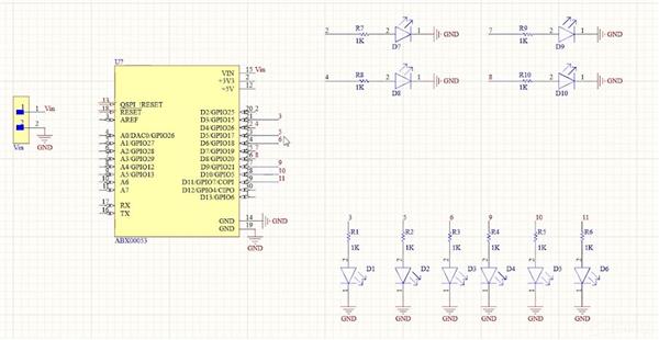
Here we are in Altium designer. Input voltage is connected to the Vin pin of Arduino. The ground pin is connected to the ground pin of Arduino. Digital Pins from 2 to 11 are connected to LEDs via resistors.

Pin numbers 3, 5, 6, 9, 10, and 11 are PWM pins using which we will be able to fade in and fade out the LEDs which will create a heartbeat effect. All other pins – 2, 4, 7, and 8 are Digital Pins that will be on all the time.
The next step is where we deviate from all the previous projects. Here we will be designing a Heart-shaped PCB where we can securely solder the Arduino, the header pins, transistors, resistors as well as LEDs.
Designing the Heartshaped PCB
The first thing we need is the shape of a Heart. For that, you can draw a heart using these tools or you can import a heart shape saved as a DXF file. For this project, I decided to go with the second option. I will leave the link to this DXF file in the description.
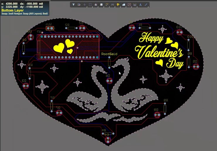
To import the heart go to files import and select DXF/DWG file. Browse the file and hit open. If you want you can resize the heart to fit all the components. Once the heart is in the right size, we can define the boat shape using this drawing. For that go to design, board shape, and define board shape from selected objects. And there we go. The board shape has been designed. Now you can arrange all the components inside this heart and once you have arranged all the components you can route it and export the Gerber files.

Getting the PCB Done!
I ordered PCB from PCBWay. PCBWay is a PCB manufacturer specializing in PCB prototyping, low-volume production, and neat and tidy PCB assembly and you can create a variety of PCBs with different specifications. We will look into it in a second.
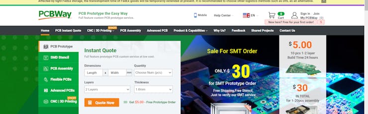
To order our PCB from PCB way, go to the PCBWay website and fill in the basic board details in the instant order form. From there we will be directed to a form where we can provide more elaborate board details. Under advanced PCBs, you can customize your PCBs.
Now update the board information in the PCB specification screen. I want to give the red color to these PCBs, so I chose the red color for the solder mask.
In PCBWay, we can select a variety of color PCBs such as purple, black, orange, and even create transparent PCBs by selecting a transparent solder mask.
Also, I chose a white silkscreen instead of black. Perfect. On the next screen, we should be able to upload the Gerber file and submit it for review. Once the review is completed, all that is left is to add to the cart, make payment, and wait for the PCBs to arrive.
Coding
void setup() {
pinMode(2, OUTPUT);
pinMode(3, OUTPUT);
pinMode(4, OUTPUT);
pinMode(5, OUTPUT);
pinMode(6, OUTPUT);
pinMode(7, OUTPUT);
pinMode(8, OUTPUT);
pinMode(9, OUTPUT);
pinMode(10, OUTPUT);
pinMode(11, OUTPUT);
}

void loop() {
  analogWrite(2, 255);
  analogWrite(4, 255);
  analogWrite(7, 255);
  analogWrite(8, 255);
   for (int i = 0; i < 255; i = i + 7) {
    analogWrite(11, i);
    analogWrite(3, i);
    analogWrite(5, i);
    analogWrite(6, i);
    analogWrite(9, i);
    analogWrite(10, i);
    delay(5);
  }
  for (int i = 255; i > 0; i = i - 7) {
    analogWrite(3, i);
    analogWrite(5, i);
    analogWrite(6, i);
    analogWrite(9, i);
    analogWrite(10, i);
    analogWrite(11, i);
    delay(5);
  }
  delay(200);
  for (int i = 0; i < 255; i = i + 7) {
    analogWrite(11, i);
    analogWrite(3, i);
    analogWrite(5, i);
    analogWrite(6, i);
    analogWrite(9, i);
    analogWrite(10, i);
    delay(5);
  }
  for (int i = 255; i > 0; i = i - 7) {
    analogWrite(3, i);
    analogWrite(5, i);
    analogWrite(6, i);
    analogWrite(9, i);
    analogWrite(10, i);
    analogWrite(11, i);
    delay(5);
  }
  delay(400);
}
Testing
Awesome right? Now all you have to do is program our Arduino. I will provide the link to the code in the description.
So here we go, guys. Beating Heart PCBs. We hope you’ve enjoyed our Beating heart project.
Beating Heart PCB for Valentines Day | Love is in the Circuit
*PCBWay community is a sharing platform. We are not responsible for any design issues and parameter issues (board thickness, surface finish, etc.) you choose.


Raspberry Pi 5 7 Inch Touch Screen IPS 1024x600 HD LCD HDMI-compatible Display for RPI 4B 3B+ OPI 5 AIDA64 PC Secondary Screen(Without Speaker)
BUY NOW


- Comments(1)
- Likes(4)
 More by Krishna S
-
 DIY Home Automation using Arduino UNO R4
Welcome to this beginner's guide to making your own home automation system, leveraging the prowess o...
DIY Home Automation using Arduino UNO R4
Welcome to this beginner's guide to making your own home automation system, leveraging the prowess o...
-
 Getting Plants Watered Automatically: A Guide to Scheduling
In this guide, we'll explore how using a scheduler in your DIY electronic projects can automate your...
Getting Plants Watered Automatically: A Guide to Scheduling
In this guide, we'll explore how using a scheduler in your DIY electronic projects can automate your...
-
 DIY Motion Triggered Halloween Prop using Arduino/Digispark
Having Halloween decorations that come to life is absolutely fun. Unfortunately, there are significa...
DIY Motion Triggered Halloween Prop using Arduino/Digispark
Having Halloween decorations that come to life is absolutely fun. Unfortunately, there are significa...
-
 Control your Home Devices using Arduino and Personal Assistant
IntroductionIn the previous video, we build an Alexa-controlled Door Locking System. So many people ...
Control your Home Devices using Arduino and Personal Assistant
IntroductionIn the previous video, we build an Alexa-controlled Door Locking System. So many people ...
-
 Making A Gesture Controller Glove using Hall Effect Sensor
StoryHey guys, in this video, we will be making a compact circuit that can be fitted in a glove to c...
Making A Gesture Controller Glove using Hall Effect Sensor
StoryHey guys, in this video, we will be making a compact circuit that can be fitted in a glove to c...
-
 Voice Controlled Door Lock using Alexa and Arduino
Voice Controlled Door Lock: An OverviewHey, everyone! Welcome back. In this video, we'll make an Ale...
Voice Controlled Door Lock using Alexa and Arduino
Voice Controlled Door Lock: An OverviewHey, everyone! Welcome back. In this video, we'll make an Ale...
-
 Making a DIY Soldering Fume Extractor with Lighting
IntroductionSoldering is awesome, right? It's fun to make our own PCB for our project, but there are...
Making a DIY Soldering Fume Extractor with Lighting
IntroductionSoldering is awesome, right? It's fun to make our own PCB for our project, but there are...
-
 Driving 4 High Current Motors in your Robot using a Simple L293D Piggy Backed Arduino Nano Shield
StoryHey, guys welcome back, In this post, I will show you how you can make your own high current mo...
Driving 4 High Current Motors in your Robot using a Simple L293D Piggy Backed Arduino Nano Shield
StoryHey, guys welcome back, In this post, I will show you how you can make your own high current mo...
-
 USB Joystick using Arduino for Robotics and Computer Game
Hey guys, in this video, we are going to make an amazing compact joystick using Arduino. We can use ...
USB Joystick using Arduino for Robotics and Computer Game
Hey guys, in this video, we are going to make an amazing compact joystick using Arduino. We can use ...
-
 How to make an Arduino UNO at Home? DIY Arduino
In this project, we are going to be making our own customized Arduino Uno board and I will be showin...
How to make an Arduino UNO at Home? DIY Arduino
In this project, we are going to be making our own customized Arduino Uno board and I will be showin...
-
 Beating Heart PCB for Valentines Day | Love is in the Circuit
Hey guys it’s valentine’s day! So let me ask you a question. what gift are you going to give to your...
Beating Heart PCB for Valentines Day | Love is in the Circuit
Hey guys it’s valentine’s day! So let me ask you a question. what gift are you going to give to your...
-
 5V – 3.3V Logic Level Shifter IC for Arduino and Raspberry Pi
Hey, Guys welcome back to RootSaid. In ...
5V – 3.3V Logic Level Shifter IC for Arduino and Raspberry Pi
5V – 3.3V Logic Level Shifter IC for Arduino and Raspberry PiHey, Guys welcome back to RootSaid. In ...
-
 Lets make an IOT based plant watering system using Arduino Nano 33 IoT, some pumps and an Android Smart Phone.
IntroductionHome automation is a popular subject these days and with excellent cause. Our smart devi...
Lets make an IOT based plant watering system using Arduino Nano 33 IoT, some pumps and an Android Smart Phone.
IntroductionHome automation is a popular subject these days and with excellent cause. Our smart devi...
-
 DIY Photoshop Editing Console using Arduino Nano RP 2040
Making a DIY Photoshop Editing ConsoleWhat if there was something that we could use to quickly chang...
DIY Photoshop Editing Console using Arduino Nano RP 2040
Making a DIY Photoshop Editing ConsoleWhat if there was something that we could use to quickly chang...
-
 DIY Halloween Pumpkin using Arduino
It’s time to get ready for Halloween! We’re going to be doing a lot of DIY stuff this month, so stay...
DIY Halloween Pumpkin using Arduino
It’s time to get ready for Halloween! We’re going to be doing a lot of DIY stuff this month, so stay...
-
 Drink Like James Bond! DIY Cocktail Mixer Using Arduino
Robotic BartenderThis weekend you can make your next cocktail party an even bigger success by buildi...
Drink Like James Bond! DIY Cocktail Mixer Using Arduino
Robotic BartenderThis weekend you can make your next cocktail party an even bigger success by buildi...
-
-
ARPS-2 – Arduino-Compatible Robot Project Shield for Arduino UNO
1256 0 4 -
A Compact Charging Breakout Board For Waveshare ESP32-C3
1774 3 7 -
AI-driven LoRa & LLM-enabled Kiosk & Food Delivery System
1752 2 0 -
-
-
-
ESP32-C3 BLE Keyboard - Battery Powered with USB-C Charging
1927 0 1 -


