


|
C503B-RAN-CZ0C0AA2Cree LED
|
x 1 | |
|
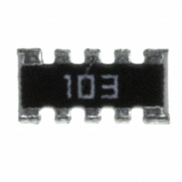
746X101103JPCTS Resistor Products
|
x 1 |

|
AltiumAltium
|
5V – 3.3V Logic Level Shifter IC for Arduino and Raspberry Pi
5V – 3.3V Logic Level Shifter IC for Arduino and Raspberry Pi
Hey, Guys welcome back to RootSaid. In this post, I will show you how you can make your own 5V to 3.3V logic Shifter for connecting 5V sensors to new Arduino Boards and Raspberry Pi.
Why do we need a Logic Level Shifter IC?
Most of you love playing with Arduino and Raspberry Pi during your free time right? Of Course, that’s what hobbyists do!
Along with Arduino, we will definitely use various sensors such as IR sensor, PIR sensor, and Ultrasonic sensor. But the problem is most of today’s boards are not 5 V tolerant and almost all of the boards work under 3.3V.
Does that mean we can't use our old sensors anymore?
Not exactly. Almost all of the microcontrollers work under 3.3V logic these days. Most of the devices that work under 3.3V do not like being provided with 5V and will get burned in seconds. So what can we do about it? Luckily, there is a way, there are logic level shifters that will convert 5V to 3.3V. One such IC is 74LVC245.
74LVC245 Logic Level Shifter IC
This chip solves the problem of connecting and sending data from 5 V logic level devices to 3.3 V logic microcontrollers such as Raspberry Pi and Arduino. This chip stands in between Arduino and the Sensor and converts the 5V signals from the sensor to 3.3V which can be directly fed to Arduino.
74LVC245 can be used with digital signals and works great with SPI, Serial, Parallel bus, and other logic interfaces.
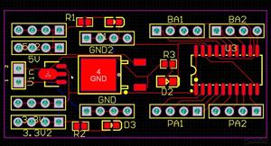
Designing the Circuit 74LVC245 Logic Level Converter IC
I used Altium Designer to draw the circuit and design the PCB. It is a powerful tool that can be used to design and create your own PCBs for your project as well as complex and multiplayer PCBs for industrial use. Here is the link to the Altium trial version. So make sure you check it out.
Working with this IC is pretty simple. You can set up the circuit in a matter of minutes.
Simply connect VCC to the logic level you want to convert to. If you are converting 5V to 3.3V, connect-
- 3.3V to VCC.
- Ground connects to Ground.
- OE (output enable) to ground to enable the chip
- DIR to VCC (3.3V).
Once you have finished drawing the circuit, save the circuit by clicking save and creating the PCB layout.
Getting PCB Done
I ordered PCB from PCBWay. PCBWay is a PCB manufacturer specializing in PCB prototyping, low-volume production, and neat and tidy PCB assembly.
To order your PCB from PCBWay, go to the PCBWay website and fill in the basic board details in the instant order form. From there you will be directed to a form where you can provide more elaborate board details.
Update your board information in the PCB specification screen. On the next screen, you should be able to upload your Gerber file and submit it for review. Once the review is completed, all that is left is to add to the cart, make payment, and wait for your PCBs to arrive.
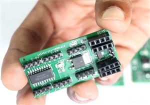
Once you get all the components and the PCB, it’s time for you to solder them together. Solder all the components onto the board and make sure to check the polarity of the components. After soldering the PCB looks like this.
I personally find soldering on this kind of PCBs a fun task, because of these pads soldering becomes very easy. The solder takes up the conical shape and gets soldered from all the sides evenly. After soldering the PCB looks like this.
This is the assembled board. Neat and Clean. Once you get the board, you can take one and solder the remaining components into it. I have soldered the header pins and this is the finished board.
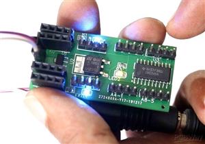
Testing the 5V to 3.3V Logic Level Shifter
Now if you connect the 5 V Signals at A Pins, you will get 3.3 V at corresponding B Pins.
Now we will check that by connecting a 5V in A1 and 0V in A5
So this will give 3.3V Out at B1 and 0V at B5.

5V – 3.3V Logic Level Shifter IC for Arduino and Raspberry Pi


Raspberry Pi 5 7 Inch Touch Screen IPS 1024x600 HD LCD HDMI-compatible Display for RPI 4B 3B+ OPI 5 AIDA64 PC Secondary Screen(Without Speaker)
BUY NOW


- Comments(0)
- Likes(0)
 More by Krishna S
-
 DIY Home Automation using Arduino UNO R4
Welcome to this beginner's guide to making your own home automation system, leveraging the prowess o...
DIY Home Automation using Arduino UNO R4
Welcome to this beginner's guide to making your own home automation system, leveraging the prowess o...
-
 Getting Plants Watered Automatically: A Guide to Scheduling
In this guide, we'll explore how using a scheduler in your DIY electronic projects can automate your...
Getting Plants Watered Automatically: A Guide to Scheduling
In this guide, we'll explore how using a scheduler in your DIY electronic projects can automate your...
-
 DIY Motion Triggered Halloween Prop using Arduino/Digispark
Having Halloween decorations that come to life is absolutely fun. Unfortunately, there are significa...
DIY Motion Triggered Halloween Prop using Arduino/Digispark
Having Halloween decorations that come to life is absolutely fun. Unfortunately, there are significa...
-
 Control your Home Devices using Arduino and Personal Assistant
IntroductionIn the previous video, we build an Alexa-controlled Door Locking System. So many people ...
Control your Home Devices using Arduino and Personal Assistant
IntroductionIn the previous video, we build an Alexa-controlled Door Locking System. So many people ...
-
 Making A Gesture Controller Glove using Hall Effect Sensor
StoryHey guys, in this video, we will be making a compact circuit that can be fitted in a glove to c...
Making A Gesture Controller Glove using Hall Effect Sensor
StoryHey guys, in this video, we will be making a compact circuit that can be fitted in a glove to c...
-
 Voice Controlled Door Lock using Alexa and Arduino
Voice Controlled Door Lock: An OverviewHey, everyone! Welcome back. In this video, we'll make an Ale...
Voice Controlled Door Lock using Alexa and Arduino
Voice Controlled Door Lock: An OverviewHey, everyone! Welcome back. In this video, we'll make an Ale...
-
 Making a DIY Soldering Fume Extractor with Lighting
IntroductionSoldering is awesome, right? It's fun to make our own PCB for our project, but there are...
Making a DIY Soldering Fume Extractor with Lighting
IntroductionSoldering is awesome, right? It's fun to make our own PCB for our project, but there are...
-
 Driving 4 High Current Motors in your Robot using a Simple L293D Piggy Backed Arduino Nano Shield
StoryHey, guys welcome back, In this post, I will show you how you can make your own high current mo...
Driving 4 High Current Motors in your Robot using a Simple L293D Piggy Backed Arduino Nano Shield
StoryHey, guys welcome back, In this post, I will show you how you can make your own high current mo...
-
 USB Joystick using Arduino for Robotics and Computer Game
Hey guys, in this video, we are going to make an amazing compact joystick using Arduino. We can use ...
USB Joystick using Arduino for Robotics and Computer Game
Hey guys, in this video, we are going to make an amazing compact joystick using Arduino. We can use ...
-
 How to make an Arduino UNO at Home? DIY Arduino
In this project, we are going to be making our own customized Arduino Uno board and I will be showin...
How to make an Arduino UNO at Home? DIY Arduino
In this project, we are going to be making our own customized Arduino Uno board and I will be showin...
-
 Beating Heart PCB for Valentines Day | Love is in the Circuit
Hey guys it’s valentine’s day! So let me ask you a question. what gift are you going to give to your...
Beating Heart PCB for Valentines Day | Love is in the Circuit
Hey guys it’s valentine’s day! So let me ask you a question. what gift are you going to give to your...
-
 5V – 3.3V Logic Level Shifter IC for Arduino and Raspberry Pi
Hey, Guys welcome back to RootSaid. In ...
5V – 3.3V Logic Level Shifter IC for Arduino and Raspberry Pi
5V – 3.3V Logic Level Shifter IC for Arduino and Raspberry PiHey, Guys welcome back to RootSaid. In ...
-
 Lets make an IOT based plant watering system using Arduino Nano 33 IoT, some pumps and an Android Smart Phone.
IntroductionHome automation is a popular subject these days and with excellent cause. Our smart devi...
Lets make an IOT based plant watering system using Arduino Nano 33 IoT, some pumps and an Android Smart Phone.
IntroductionHome automation is a popular subject these days and with excellent cause. Our smart devi...
-
 DIY Photoshop Editing Console using Arduino Nano RP 2040
Making a DIY Photoshop Editing ConsoleWhat if there was something that we could use to quickly chang...
DIY Photoshop Editing Console using Arduino Nano RP 2040
Making a DIY Photoshop Editing ConsoleWhat if there was something that we could use to quickly chang...
-
 DIY Halloween Pumpkin using Arduino
It’s time to get ready for Halloween! We’re going to be doing a lot of DIY stuff this month, so stay...
DIY Halloween Pumpkin using Arduino
It’s time to get ready for Halloween! We’re going to be doing a lot of DIY stuff this month, so stay...
-
 Drink Like James Bond! DIY Cocktail Mixer Using Arduino
Robotic BartenderThis weekend you can make your next cocktail party an even bigger success by buildi...
Drink Like James Bond! DIY Cocktail Mixer Using Arduino
Robotic BartenderThis weekend you can make your next cocktail party an even bigger success by buildi...
-
-
ARPS-2 – Arduino-Compatible Robot Project Shield for Arduino UNO
1285 0 4 -
A Compact Charging Breakout Board For Waveshare ESP32-C3
1797 3 7 -
AI-driven LoRa & LLM-enabled Kiosk & Food Delivery System
1787 2 0 -
-
-
-
ESP32-C3 BLE Keyboard - Battery Powered with USB-C Charging
1965 0 1 -


