


|
|
Switch Button |
x 3 | |
|
|
Reed Switch Sensor |
x 1 | |
|
|
LCD 16 x 2 Display (I2C) |
x 1 | |
|
|
Arduino Nano |
x 1 | |
|
|
10k Resistor |
x 4 |
Arduino Bicycle Odometer
Introduction
In many vehicles, there are devices that calculate the distance traveled and are essential for presenting information to the driver. Thus, through this information, it is possible to monitor the distance traveled between two points, for example, through the vehicle odometer.
Therefore, through this article, we will teach you how to assemble your distance calculation device using the reed switch sensor.
The Project
The following project was created to calculate the percorred distance by the bicycle of the gym. In addition to, you'll learn how to create a programming of the project.
This project has three functionalides:
- Calculate the distance traveled by the bicycle;
- Device Startup Radius Configuration;
- Adaptable to any bike.
To access these functionalities, the user will use the three buttons of the system. Each button have your functionality. In the system we have the following buttons:
- Increment Button: It will used to enter in the option to configure the radius of the wheels and increment the radius value;
- Decrement Button: It will used to decrement the option to configure the radius of the wheels;
- Enter Button: It will used to insert the value of the radius in the system.
In addition to, we have the Reed Switch Sensor. It is responsible to detect when the wheels do a complete turn. For detecting this, is need install a magnet on the wheels. The Reed Switch is presented in the Figure 1.

Figure 1 - Reed Switch Sensor.
Thus, every time the magnet approaches the sensor, it will actuate the Reed Switch sensor. The process works through the following equation:
Travelled Distance = 2 * π * radius * TurnNumber
Through this equation, we'll know what is the travelled distance percorred by the bicycle. In the equation, the radius is inserted by the user and Turn Number is calculated through of the number of turns of the wheel. And to detect the turns of the wheel is need to install a magnet in the bicycle wheel and to install the Reed Switch Sensor near the Wheel.
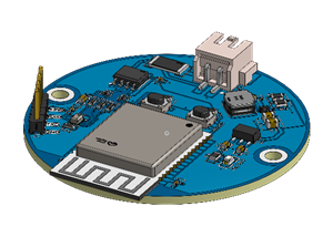
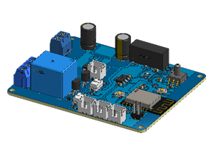
To easier the process, we create a printed circuit board to connect the Reed Switch Sensor and the three buttons. The Printed Circuit Board is presented below in the Figure 2.

Figure 2 - Printed Circuit Board of the Project.
As is shown in the PCB is possible see the Arduino Nano. It is responsible to control all system. In addition to, we have 5 JST connectors. The C1 until C4 connectors are used to connect the three buttons and the Reed Switch Sensor. Now, the C5 Connector is used to connect the LCD 16x2 I2C.
Therefore, through this system, you can install the project in your bicycle and obtain the travelled distance value.
For this, you can use the code presented below.
#include <EEPROM.h>
#include <LiquidCrystal.h>

/*
Pinos de conex?o dos bot?es e sensor reed switch
8 — Sensor Reed Switch
9 — Decremento
12 — Incremento
11 — Enter
*/

#define MEMORIA 120
#define PosRaio 125

#define ReedSwitch 8
#define BotaoEnterOk 11
#define BotaoIncremento 12
#define BotaoDecremento 9

const int rs = 2, en = 3, d4 = 4, d5 = 5, d6 = 6, d7 = 7;
LiquidCrystal lcd(rs, en, d4, d5, d6, d7);

bool sensor = 0, estado_anterior = 0, Incremento = 0, Decremento = 0;
bool IncrementoAnterior = 0, DecrementoAnterior = 0, BotaoEnter = 0, EstadoAnteriorIncremento = 0;

byte cont = 0;

unsigned long int VoltaCompleta = 0;
unsigned long int tempo_atual = 0, ultimo_tempo = 0;

float DistKm = 0;
unsigned int raio = 0;
float Distancia = 0;

void setup()
{
Serial.begin(9600);
pinMode(8, INPUT);
pinMode(9, INPUT);
pinMode(10, INPUT);
pinMode(12, INPUT);

lcd.begin(16,2);

//Regiao de codigo para configurar o raio da roda do veiculo
if(EEPROM.read(MEMORIA) != 73)
{
ConfiguraRaio();
EEPROM.write(MEMORIA, 73);
}

lcd.setCursor(3,0);
lcd.print(“Distancia”);
lcd.setCursor(6,1);
lcd.print(Distancia);

lcd.setCursor(14,1);
lcd.print(“km”);

raio = EEPROM.read(PosRaio);
}

void loop()
{

//Regiao de codigo para realizar a leitura dos botoes e sensor do dispositivo
sensor = digitalRead(ReedSwitch);
Decremento = digitalRead(BotaoDecremento);
Incremento = digitalRead(BotaoIncremento);

//Regiao de codigo para acumular a distancia percorrida
if(sensor == 0 && estado_anterior == 1)
{
VoltaCompleta++;

Distancia = (float)(2*3.14*raio*VoltaCompleta)/100000.0;

lcd.setCursor(0,1);
lcd.print(“ “);
lcd.setCursor(6,1);
lcd.print(Distancia);

lcd.setCursor(14,1);
lcd.print(“km”);

estado_anterior = 0;
}

if(sensor == 1 && estado_anterior == 0)
{
estado_anterior = 1;
}

//Regiao de Codigo para Configurar o Raio
if(Incremento == 1 && EstadoAnteriorIncremento == 0)
{
EstadoAnteriorIncremento = 1;
}

if(Incremento == 0 && EstadoAnteriorIncremento == 1)
{
EstadoAnteriorIncremento = 0;
lcd.clear();
ConfiguraRaio();
}
}

void ConfiguraRaio()
{

byte RaioRoda = 0;

//Imprimir mensagem para digitar o raio em cm
lcd.setCursor(0,0);
lcd.print(“Inserir Raio(cm)”);

do
{

lcd.setCursor(6,1);

Incremento = digitalRead(BotaoIncremento);
Decremento = digitalRead(BotaoDecremento);
BotaoEnter = digitalRead(BotaoEnterOk);

if(Incremento == 1 && IncrementoAnterior == 0)
{
RaioRoda = RaioRoda + 1;
IncrementoAnterior = 1;
}

if(Incremento == 0 && IncrementoAnterior == 1)
{
IncrementoAnterior = 0;
}

if(Decremento == 1 && DecrementoAnterior == 0)
{
RaioRoda = RaioRoda — 1;
DecrementoAnterior = 1;
}

if(Decremento == 0 && DecrementoAnterior == 1)
{
DecrementoAnterior = 0;
}

lcd.setCursor(6,1);
lcd.print(RaioRoda);

}while(BotaoEnter == 0);

lcd.clear();

EEPROM.write(PosRaio, RaioRoda);
return;
}
Conclusion
Therefore, case you want your own PCB, you can obtain 10 free units through the discount coupon of the PCBWay. For this, you can access the website, create your account and obtain your own PCB's.
Arduino Bicycle Odometer
*PCBWay community is a sharing platform. We are not responsible for any design issues and parameter issues (board thickness, surface finish, etc.) you choose.


Raspberry Pi 5 7 Inch Touch Screen IPS 1024x600 HD LCD HDMI-compatible Display for RPI 4B 3B+ OPI 5 AIDA64 PC Secondary Screen(Without Speaker)
BUY NOW


- Comments(0)
- Likes(2)
- 1 USER VOTES
- YOUR VOTE 0.00 0.00

-
10design
-
8usability
-
8creativity
-
10content
More by Silícios Lab silicioslab
-
 How to measure weight with Load Cell and HX711
IntroductionThe purpose of this project is to develop a printed circuit board (PCB) that allows weig...
How to measure weight with Load Cell and HX711
IntroductionThe purpose of this project is to develop a printed circuit board (PCB) that allows weig...
-
 Electronic Enclosure applied for electronic projects
IntroductionWhen designing electronics, the enclosure plays a crucial role that is often overlooked....
Electronic Enclosure applied for electronic projects
IntroductionWhen designing electronics, the enclosure plays a crucial role that is often overlooked....
-
 IoT Indoor system with ESP32 to monitor Temperature, Humidity, Pressure, and Air Quality
IntroductionAir quality, temperature, humidity and pressure are essential elements to ensure healthy...
IoT Indoor system with ESP32 to monitor Temperature, Humidity, Pressure, and Air Quality
IntroductionAir quality, temperature, humidity and pressure are essential elements to ensure healthy...
-
 WS2812B RGB LED Controller with ESP8266 via WiFi
IntroductionWS2812b addressable RGB LEDs are devices widely used in lighting projects. They are foun...
WS2812B RGB LED Controller with ESP8266 via WiFi
IntroductionWS2812b addressable RGB LEDs are devices widely used in lighting projects. They are foun...
-
 Electronic Board for Cutting Electrical Power to Devices and Machines
IntroductionAn energy saving system for cutting electrical energy in machines is a fundamental piece...
Electronic Board for Cutting Electrical Power to Devices and Machines
IntroductionAn energy saving system for cutting electrical energy in machines is a fundamental piece...
-
 PCB Board Home Automation with ESP8266
IntroductionThe incorporation of the ESP8266 module into home automation represents a significant ad...
PCB Board Home Automation with ESP8266
IntroductionThe incorporation of the ESP8266 module into home automation represents a significant ad...
-
 Dedicated Control Board for Mobile Robots with Wheels
IntroductionFor a long time we developed several prototypes and teaching kits of mobile robots and w...
Dedicated Control Board for Mobile Robots with Wheels
IntroductionFor a long time we developed several prototypes and teaching kits of mobile robots and w...
-
 Traffic turn signal for bicycles
IntroductionDoes every project with electronic logic need a Microcontroller or Arduino to be develop...
Traffic turn signal for bicycles
IntroductionDoes every project with electronic logic need a Microcontroller or Arduino to be develop...
-
 Mini Arduino with ATTINY85
Do you know the ATTINY85 microcontroller? This article has news and a gift for you. Many people deve...
Mini Arduino with ATTINY85
Do you know the ATTINY85 microcontroller? This article has news and a gift for you. Many people deve...
-
 Christmas Tree
The tree used to signal light of Christmas.
Christmas Tree
The tree used to signal light of Christmas.
-
 Electronic Fish Feeder
Never forget to feed your fish again and with the right amount, at the right time.Regular feeding is...
Electronic Fish Feeder
Never forget to feed your fish again and with the right amount, at the right time.Regular feeding is...
-
 ESP32 BMP280 Pressure Monitor
IntroductionMonitoring environmental variables is crucial for the efficiency and safety of numerous ...
ESP32 BMP280 Pressure Monitor
IntroductionMonitoring environmental variables is crucial for the efficiency and safety of numerous ...
-
 Smart Pressure Control: The IoT Pressure Monitor
Introduction and ObjectiveThe ProblemIn the development of electronic monitoring systems, we often e...
Smart Pressure Control: The IoT Pressure Monitor
Introduction and ObjectiveThe ProblemIn the development of electronic monitoring systems, we often e...
-
 IoT Access control and communication system with Raspberry Pi/PC using ESP32
IntroductionIn the world of automation and the Internet of Things (IoT), access control systems have...
IoT Access control and communication system with Raspberry Pi/PC using ESP32
IntroductionIn the world of automation and the Internet of Things (IoT), access control systems have...
-
 Electronic Enclosure applied for electronic devices
IntroductionWhen designing electronics, the enclosure plays a crucial role that is often overlooked....
Electronic Enclosure applied for electronic devices
IntroductionWhen designing electronics, the enclosure plays a crucial role that is often overlooked....
-
 Electronic Enclosure for Programmable Logic Controller
The housing developed for programmable logic controllers is a practical and efficient solution for t...
Electronic Enclosure for Programmable Logic Controller
The housing developed for programmable logic controllers is a practical and efficient solution for t...
-
 Payment PCB for machines and services
IntroductionIn many commercial establishments, hospitals and other places, there are video game equi...
Payment PCB for machines and services
IntroductionIn many commercial establishments, hospitals and other places, there are video game equi...
-
 Relay High Power Printed Circuit Board
IntroductionEfficient management of electrical loads is essential for optimizing performance and saf...
Relay High Power Printed Circuit Board
IntroductionEfficient management of electrical loads is essential for optimizing performance and saf...
-
Programmable Mist Maker - XIAO / QT PY Extension
229 0 0 -
RadioHAT - Raspberry Pi radio development platform
252 0 1 -
-
-
-
-
ARPS-2 – Arduino-Compatible Robot Project Shield for Arduino UNO
2810 0 5 -
A Compact Charging Breakout Board For Waveshare ESP32-C3
3312 3 8 -
AI-driven LoRa & LLM-enabled Kiosk & Food Delivery System
3595 2 2


