


Electronic Board for Cutting Electrical Power to Devices and Machines
Introduction
An energy saving system for cutting electrical energy in machines is a fundamental piece not only to reduce operational costs, but also to promote sustainable and efficient practices in the most diverse industrial sectors. This system is designed not only to interrupt the energy supply, but also to optimize consumption, bringing significant economic and environmental benefits.
The applications of this system are varied and impactful. In industrial production lines, for example, the implementation of this system allows not only the efficient shutdown of machines during periods of inactivity, but also the precise control of energy consumption during manufacturing processes. In the automotive industry, it is possible to adjust energy use in robots and assembly equipment, reducing waste and optimizing operation.
Furthermore, in environments such as commercial buildings and public facilities, energy saving systems are essential for managing consumption during times of low demand, turning off non-essential equipment and reducing the use of electrical energy when it is not necessary.
In summary, an energy saving system for cutting electrical power to machines not only contributes to reducing operating costs, but also plays a vital role in preserving natural resources by promoting sustainable and efficient practices across a wide range of industrial and commercial sectors.
In this article you will learn how to create an electrical power cut circuit for machines when a door is open. This project was a system that I developed for a customer and I will show you how it can be useful for you. The client allowed me to present the project in the communities.
Now, let's understand the complete functioning of this practical project.
Project Electronic Circuit
First, let's start presenting the electronic schematic.

Next, we will understand how each block of the circuit works. To start, let's present the power circuit block.
Power supply circuit
The purpose of this circuit is to receive an input voltage between 110V and 220V from the electrical network to power the control system. See the circuit block shown in the figure below.

The first stage of the circuit consists of a fuse (connectors U4 and U5) and a varistor R8. The purpose of this circuit is to protect the input of the power supply circuit and prevent possible damage from overload or short circuit of the electrical network.
After that, we have the Hilink U1 AC-DC converter, which is responsible for converting the input AC voltage to a value of 5V direct current. This direct voltage will be used to power the entire electronic direct current circuit of the system.
Note that we use component B0505S, represented by U2. It is an isolated DC-DC converter and its purpose is to receive an input voltage of 5V and provide an isolated voltage of 5V at its output.
Its purpose is to create an isolated and dedicated 5V voltage just to power the ATTINY85 Microcontroller circuit.
The 5V voltage, which comes from the Hilink source output, will be used to power the relay drive circuit. This way, if any noise occurs at this source, it will not pass to the Microcontroller, as they are completely isolated.
Next, we will present the ATTINY85 circuits and energized board signal.
Power Signaling Circuit and ATTINY85 Circuit
Every electronic project needs signaling to indicate that it is energized. This circuit has two purposes: to indicate circuit energization to avoid accidents and to facilitate the identification of possible problems in power supply circuits.
In the figure below we represent a resistor in series with an LED. The LED will be activated every time the board is energized and the HiLink converter provides 5V voltage.

The ATTINY85 circuit is quite simple. The CHIP is made up of 8 pins. Of these pins, 2 were used for power supply, 2 I/O pins were used to connect the sensor and the relay drive circuit, and the reset pin.
Below is the presentation of the reset circuit and the power and sensor connectors.
Reset Circuit and Connectors for powering the circuit and sensors
The reset button is intended to allow the user to restart the application, if necessary.

The door open sensor circuit is connected to pin D2. The H2 connector is used to power the circuit and connect the phase wire to the relay. This wire will be disconnected when the system detects that the door is open or closed.
Now we will talk about the relay activation circuit.
Relay Drive Circuit
The relay drive circuit is connected to digital pin D1 of the ATTINY85.
One very important thing to mention is that this circuit has its power isolated from the ATTINY85 power circuit. This is because we use the B0505S device.

Therefore, there are 2 different GNDs in the circuit and this prevents, for example, resetting the ATTINY85 if any noise occurs during the relay activation process. For this circuit we use an optocoupler.
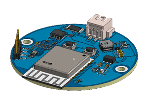
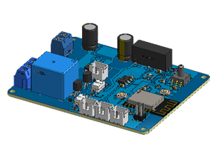
Next, we will present the result of the printed circuit board with the components soldered into its structure.
Prototype Result
Below we present the result of the printed circuit board with the electronic components mounted on its structure.


This project worked successfully in field application and you can use it for device current cutting applications using a digital sensor.
All files are available for download.
Acknowledgments
We would like to thank PCBWAY for supportting the creation of this project and made some units available for you to earn for free and receive 5 units at your home. To receive them, access this link, create an account on the website and receive coupons for you to win right now.

Electronic Board for Cutting Electrical Power to Devices and Machines
Project images are for reference only. Actual production is based on the manufacturing files on the project page.
Please review the designer's notes (e.g., PCB thickness) and select the appropriate options.
PCBWay is not responsible
for issues caused by unsuitable parameter selections.
For more important ordering information, please refer to
Read More


Raspberry Pi 5 7 Inch Touch Screen IPS 1024x600 HD LCD HDMI-compatible Display for RPI 4B 3B+ OPI 5 AIDA64 PC Secondary Screen(Without Speaker)
BUY NOW


- Comments(0)
- Likes(0)
More by Silícios Lab silicioslab
-
 How to measure weight with Load Cell and HX711
IntroductionThe purpose of this project is to develop a printed circuit board (PCB) that allows weig...
How to measure weight with Load Cell and HX711
IntroductionThe purpose of this project is to develop a printed circuit board (PCB) that allows weig...
-
 Electronic Enclosure applied for electronic projects
IntroductionWhen designing electronics, the enclosure plays a crucial role that is often overlooked....
Electronic Enclosure applied for electronic projects
IntroductionWhen designing electronics, the enclosure plays a crucial role that is often overlooked....
-
 IoT Indoor system with ESP32 to monitor Temperature, Humidity, Pressure, and Air Quality
IntroductionAir quality, temperature, humidity and pressure are essential elements to ensure healthy...
IoT Indoor system with ESP32 to monitor Temperature, Humidity, Pressure, and Air Quality
IntroductionAir quality, temperature, humidity and pressure are essential elements to ensure healthy...
-
 WS2812B RGB LED Controller with ESP8266 via WiFi
IntroductionWS2812b addressable RGB LEDs are devices widely used in lighting projects. They are foun...
WS2812B RGB LED Controller with ESP8266 via WiFi
IntroductionWS2812b addressable RGB LEDs are devices widely used in lighting projects. They are foun...
-
 Electronic Board for Cutting Electrical Power to Devices and Machines
IntroductionAn energy saving system for cutting electrical energy in machines is a fundamental piece...
Electronic Board for Cutting Electrical Power to Devices and Machines
IntroductionAn energy saving system for cutting electrical energy in machines is a fundamental piece...
-
 PCB Board Home Automation with ESP8266
IntroductionThe incorporation of the ESP8266 module into home automation represents a significant ad...
PCB Board Home Automation with ESP8266
IntroductionThe incorporation of the ESP8266 module into home automation represents a significant ad...
-
 Dedicated Control Board for Mobile Robots with Wheels
IntroductionFor a long time we developed several prototypes and teaching kits of mobile robots and w...
Dedicated Control Board for Mobile Robots with Wheels
IntroductionFor a long time we developed several prototypes and teaching kits of mobile robots and w...
-
 Traffic turn signal for bicycles
IntroductionDoes every project with electronic logic need a Microcontroller or Arduino to be develop...
Traffic turn signal for bicycles
IntroductionDoes every project with electronic logic need a Microcontroller or Arduino to be develop...
-
 Mini Arduino with ATTINY85
Do you know the ATTINY85 microcontroller? This article has news and a gift for you. Many people deve...
Mini Arduino with ATTINY85
Do you know the ATTINY85 microcontroller? This article has news and a gift for you. Many people deve...
-
 Christmas Tree
The tree used to signal light of Christmas.
Christmas Tree
The tree used to signal light of Christmas.
-
 Electronic Fish Feeder
Never forget to feed your fish again and with the right amount, at the right time.Regular feeding is...
Electronic Fish Feeder
Never forget to feed your fish again and with the right amount, at the right time.Regular feeding is...
-
 ESP32 BMP280 Pressure Monitor
IntroductionMonitoring environmental variables is crucial for the efficiency and safety of numerous ...
ESP32 BMP280 Pressure Monitor
IntroductionMonitoring environmental variables is crucial for the efficiency and safety of numerous ...
-
 Smart Pressure Control: The IoT Pressure Monitor
Introduction and ObjectiveThe ProblemIn the development of electronic monitoring systems, we often e...
Smart Pressure Control: The IoT Pressure Monitor
Introduction and ObjectiveThe ProblemIn the development of electronic monitoring systems, we often e...
-
 IoT Access control and communication system with Raspberry Pi/PC using ESP32
IntroductionIn the world of automation and the Internet of Things (IoT), access control systems have...
IoT Access control and communication system with Raspberry Pi/PC using ESP32
IntroductionIn the world of automation and the Internet of Things (IoT), access control systems have...
-
 Electronic Enclosure applied for electronic devices
IntroductionWhen designing electronics, the enclosure plays a crucial role that is often overlooked....
Electronic Enclosure applied for electronic devices
IntroductionWhen designing electronics, the enclosure plays a crucial role that is often overlooked....
-
 Electronic Enclosure for Programmable Logic Controller
The housing developed for programmable logic controllers is a practical and efficient solution for t...
Electronic Enclosure for Programmable Logic Controller
The housing developed for programmable logic controllers is a practical and efficient solution for t...
-
 Payment PCB for machines and services
IntroductionIn many commercial establishments, hospitals and other places, there are video game equi...
Payment PCB for machines and services
IntroductionIn many commercial establishments, hospitals and other places, there are video game equi...
-
 Relay High Power Printed Circuit Board
IntroductionEfficient management of electrical loads is essential for optimizing performance and saf...
Relay High Power Printed Circuit Board
IntroductionEfficient management of electrical loads is essential for optimizing performance and saf...
-
Programmable Mist Maker - XIAO / QT PY Extension
1164 2 1 -
RadioHAT - Raspberry Pi radio development platform
974 0 2 -
-
-
-
-
ARPS-2 – Arduino-Compatible Robot Project Shield for Arduino UNO
3393 0 6 -
A Compact Charging Breakout Board For Waveshare ESP32-C3
4016 3 8 -
AI-driven LoRa & LLM-enabled Kiosk & Food Delivery System
4410 2 2


