


|
arduino IDEArduino
|
IoT Access control and communication system with Raspberry Pi/PC using ESP32
Introduction
In the world of automation and the Internet of Things (IoT), access control systems have become increasingly present, ensuring security and practicality in various environments. This article presents the development of an access control system using the ESP32, which acts as the main processing unit, receiving commands in JSON format sent by a Raspberry Pi.
By combining the versatility of the ESP32 and the processing capacity of the Raspberry Pi, this project allows for the efficient management of the activation of two relays, responsible for controlling devices such as doors, turnstiles, or other access mechanisms. In addition, we highlight the simplicity and robustness of communication between devices, exploring concepts of integration and data processing.
Throughout the article, the main steps to implement this solution will be covered, including the configuration of the devices, the communication protocol used, and details on the processing of data received via USB. This project is a practical demonstration of how to combine different technologies to create intelligent and customized solutions for access control.
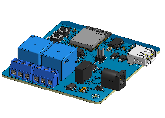
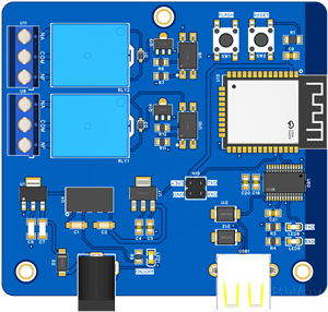
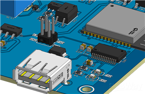
Electronic Circuit Design
The electronic circuit project is divided into 4 important blocks: the power supply circuit, the control circuit with the ESP32 Microcontroller, the relay drive circuit and the USB communication circuit for exchanging data between the ESP32 and the Raspberry PI/Orange Pi.
Below we'll present the the 3 sheets of the electronic circuits developed.
Power Supply Circuit and ESP32 Microcontroller
Firstly, we have the circuit of power supply and ESP32 microcontroller circuit.The power supply circuit was created to be powered with 9V. From this value, the voltage is regulated to a value of +5V through an AMS1117-5V.
However, we know that we have a relay drive circuit and, often, they generate interference in the operation of the ESP32 CHIP. To avoid this problem, we use the isolated DC-DC converter B0505S.
Its purpose is to convert a 5V input voltage into another 5V output voltage, in such a way that we will create a voltage source isolated from the other. Because they are isolated, we can have a dedicated power supply to power the ESP32 and this will increase the immunity of our circuit against noise coming from the input voltage source.
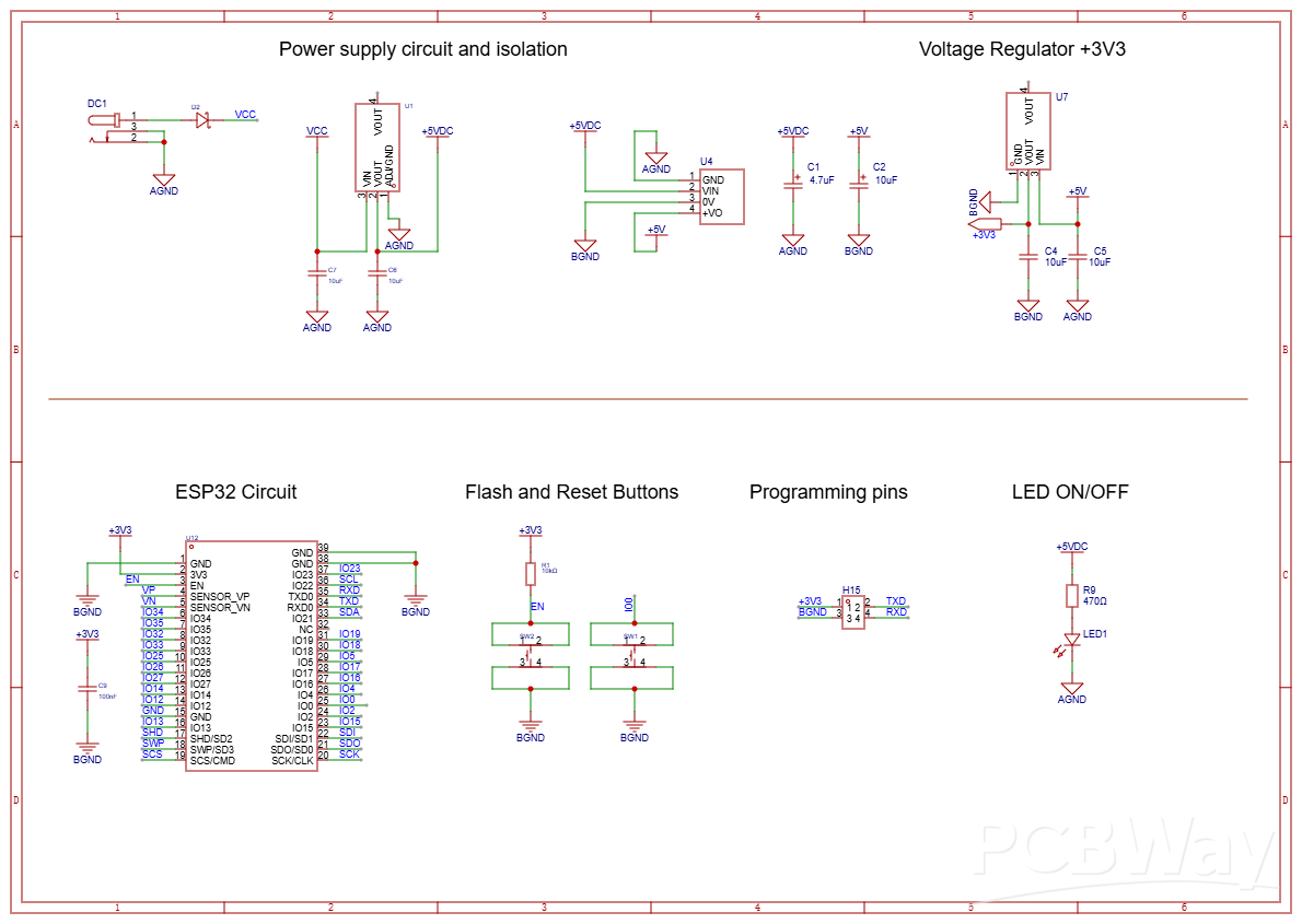
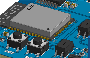
Below the power supply circuit, we have the ESP32 Microcontroller circuit. It consists of the ESP32, its buttons to put it in programming mode and the programming pins for transferring code through an external USB-Serial converter.
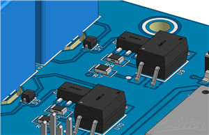
How the Relay Drive Circuit Works
The relay drive circuit uses a PC817 optocoupler IC to ensure electrical isolation between the ESP32 and the high-power components. The ESP32 sends a digital signal to the circuit, which is received by the optocoupler's internal LED. When the LED is energized, it activates the PC817's internal phototransistor, allowing current to flow through the transistor and thus activating the next stage of the circuit.
The signal from the phototransistor is used to control the base of a bipolar junction transistor (BJT) or a MOSFET, depending on the design. This transistor, when activated, allows current to pass through the relay, activating it. The relay, in turn, acts as an electromechanical switch, and can control the activation or deactivation of external loads, such as motors, lamps or other devices.
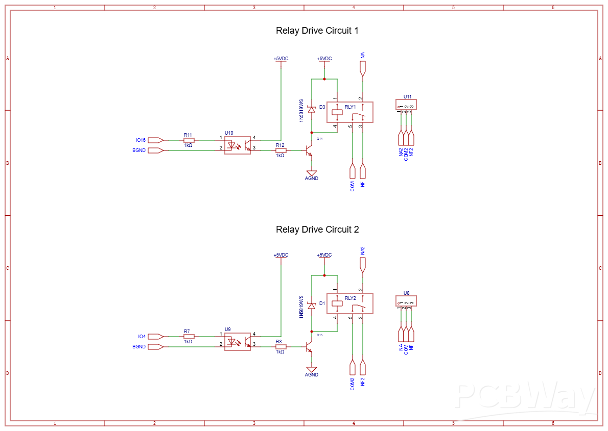
This circuit is designed to ensure that the ESP32 operates safely, isolated from possible interference or voltage spikes from the load controlled by the relays. The use of the PC817 not only protects the microcontroller, but also increases the reliability of the system in practical applications.
Finally, we have the USB communication circuit.
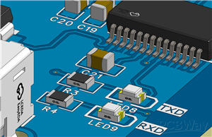
USB Communication Circuit between Raspberry Pi and ESP32
The circuit responsible for USB communication in the project aims to establish a reliable interface between the Raspberry Pi and the ESP32. To do this, we use a female USB connector, which receives the USB cable connection coming from the Raspberry Pi.
TVS (Transient Voltage Suppressor) protection diodes were implemented at the USB connector input. These components have the function of protecting the circuit against voltage surges or unwanted spikes that may arise in the data line, ensuring greater safety and longevity for the system.
The data transmitted by the Raspberry Pi is sent to the FT232RL integrated circuit, a USB to UART converter. This component converts the received USB signals to a format understandable by the ESP32, allowing it to process the information. The same path is used for the ESP32 to send data back to the Raspberry Pi, or any other compatible device, through the USB interface.
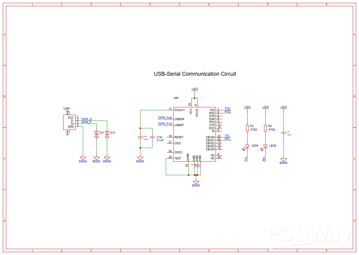
In addition, the circuit includes indicator LEDs for the TX (transmission) and RX (reception) lines. These LEDs provide visual feedback on communication, flashing when data is being sent or received, making it easier to diagnose potential problems and monitor in real time.
This USB integration with the FT232RL enables efficient communication, allowing the ESP32 to process external data and send responses, expanding the system's application possibilities in IoT and access control projects.
Conclusion
This project demonstrated how a well-designed circuit board is essential for integrating and managing the various functions of an access control system. From processing data received via JSON from the Raspberry Pi to efficiently driving relays and reliable USB communication, each component of the circuit plays a key role in ensuring the security and performance of the system.
The use of components such as the PC817 optocoupler and the FT232RL USB to UART converter not only ensures the protection and efficiency of the circuit, but also makes the project scalable and robust for practical applications. This board is not just an intermediary between devices, but the heart of the system, uniting hardware and software to deliver a complete and functional solution.
Are you ready to turn your project into reality? Order 5 PCBWay quality electronic boards now! Sign up on the website and take the next step in developing your access control system. Manufacturing quality will make all the difference in the success of your project!
IoT Access control and communication system with Raspberry Pi/PC using ESP32
*PCBWay community is a sharing platform. We are not responsible for any design issues and parameter issues (board thickness, surface finish, etc.) you choose.


Raspberry Pi 5 7 Inch Touch Screen IPS 1024x600 HD LCD HDMI-compatible Display for RPI 4B 3B+ OPI 5 AIDA64 PC Secondary Screen(Without Speaker)
BUY NOW


- Comments(0)
- Likes(1)
More by Silícios Lab silicioslab
-
 How to measure weight with Load Cell and HX711
IntroductionThe purpose of this project is to develop a printed circuit board (PCB) that allows weig...
How to measure weight with Load Cell and HX711
IntroductionThe purpose of this project is to develop a printed circuit board (PCB) that allows weig...
-
 Electronic Enclosure applied for electronic projects
IntroductionWhen designing electronics, the enclosure plays a crucial role that is often overlooked....
Electronic Enclosure applied for electronic projects
IntroductionWhen designing electronics, the enclosure plays a crucial role that is often overlooked....
-
 IoT Indoor system with ESP32 to monitor Temperature, Humidity, Pressure, and Air Quality
IntroductionAir quality, temperature, humidity and pressure are essential elements to ensure healthy...
IoT Indoor system with ESP32 to monitor Temperature, Humidity, Pressure, and Air Quality
IntroductionAir quality, temperature, humidity and pressure are essential elements to ensure healthy...
-
 WS2812B RGB LED Controller with ESP8266 via WiFi
IntroductionWS2812b addressable RGB LEDs are devices widely used in lighting projects. They are foun...
WS2812B RGB LED Controller with ESP8266 via WiFi
IntroductionWS2812b addressable RGB LEDs are devices widely used in lighting projects. They are foun...
-
 Electronic Board for Cutting Electrical Power to Devices and Machines
IntroductionAn energy saving system for cutting electrical energy in machines is a fundamental piece...
Electronic Board for Cutting Electrical Power to Devices and Machines
IntroductionAn energy saving system for cutting electrical energy in machines is a fundamental piece...
-
 PCB Board Home Automation with ESP8266
IntroductionThe incorporation of the ESP8266 module into home automation represents a significant ad...
PCB Board Home Automation with ESP8266
IntroductionThe incorporation of the ESP8266 module into home automation represents a significant ad...
-
 Dedicated Control Board for Mobile Robots with Wheels
IntroductionFor a long time we developed several prototypes and teaching kits of mobile robots and w...
Dedicated Control Board for Mobile Robots with Wheels
IntroductionFor a long time we developed several prototypes and teaching kits of mobile robots and w...
-
 Traffic turn signal for bicycles
IntroductionDoes every project with electronic logic need a Microcontroller or Arduino to be develop...
Traffic turn signal for bicycles
IntroductionDoes every project with electronic logic need a Microcontroller or Arduino to be develop...
-
 Mini Arduino with ATTINY85
Do you know the ATTINY85 microcontroller? This article has news and a gift for you. Many people deve...
Mini Arduino with ATTINY85
Do you know the ATTINY85 microcontroller? This article has news and a gift for you. Many people deve...
-
 Christmas Tree
The tree used to signal light of Christmas.
Christmas Tree
The tree used to signal light of Christmas.
-
 Electronic Fish Feeder
Never forget to feed your fish again and with the right amount, at the right time.Regular feeding is...
Electronic Fish Feeder
Never forget to feed your fish again and with the right amount, at the right time.Regular feeding is...
-
 ESP32 BMP280 Pressure Monitor
IntroductionMonitoring environmental variables is crucial for the efficiency and safety of numerous ...
ESP32 BMP280 Pressure Monitor
IntroductionMonitoring environmental variables is crucial for the efficiency and safety of numerous ...
-
 Smart Pressure Control: The IoT Pressure Monitor
Introduction and ObjectiveThe ProblemIn the development of electronic monitoring systems, we often e...
Smart Pressure Control: The IoT Pressure Monitor
Introduction and ObjectiveThe ProblemIn the development of electronic monitoring systems, we often e...
-
 IoT Access control and communication system with Raspberry Pi/PC using ESP32
IntroductionIn the world of automation and the Internet of Things (IoT), access control systems have...
IoT Access control and communication system with Raspberry Pi/PC using ESP32
IntroductionIn the world of automation and the Internet of Things (IoT), access control systems have...
-
 Electronic Enclosure applied for electronic devices
IntroductionWhen designing electronics, the enclosure plays a crucial role that is often overlooked....
Electronic Enclosure applied for electronic devices
IntroductionWhen designing electronics, the enclosure plays a crucial role that is often overlooked....
-
 Electronic Enclosure for Programmable Logic Controller
The housing developed for programmable logic controllers is a practical and efficient solution for t...
Electronic Enclosure for Programmable Logic Controller
The housing developed for programmable logic controllers is a practical and efficient solution for t...
-
 Payment PCB for machines and services
IntroductionIn many commercial establishments, hospitals and other places, there are video game equi...
Payment PCB for machines and services
IntroductionIn many commercial establishments, hospitals and other places, there are video game equi...
-
 Relay High Power Printed Circuit Board
IntroductionEfficient management of electrical loads is essential for optimizing performance and saf...
Relay High Power Printed Circuit Board
IntroductionEfficient management of electrical loads is essential for optimizing performance and saf...
-
-
ARPS-2 – Arduino-Compatible Robot Project Shield for Arduino UNO
2301 0 5 -
A Compact Charging Breakout Board For Waveshare ESP32-C3
2787 3 7 -
AI-driven LoRa & LLM-enabled Kiosk & Food Delivery System
2990 2 0 -
-
-
-
ESP32-C3 BLE Keyboard - Battery Powered with USB-C Charging
3025 0 2 -


