PCBWay Community
Search title or content
Search
PCBWay
PCB Instant Quote
CNC | 3D Printing
Login
Sign Up
More Notifications
No notifications.
My Profile
My projects
My Likes
My Deals
My Goods for Bazaar
Settings
Sign Out
Projects
Categories
DIY Electronics
Arduino
Hardware
Audio
Computers & USB
Breakout Board Projects
Home Automation
LED Displays & Matrices
IoT
Robotics
View all categories
By Source Files
Onju Voice - AI assistant replacement to Google Nest Mini by @justLV
DIY 1kW Open Source MPPT Solar Charge Controller
LogicAnalyzer V6.0
Tad Boy Color
kv4p HT v1.7b
QuinLED-Dig-Uno
SummerCart64 - a fully open source N64 flashcart
Bike Fingerprint - PCB
Arduino RC engine sound & light controller with inertia simulation for ESP32
Solar Powered WiFi Weather Station V2.0
SIDKick pico 0.2 (SID 6581/8580-replacement for C64/C128)
Frog Boy Color
View all source files projects
Featured Projects
Onju Voice - AI assistant replacement to Google Nest Mini by @justLV
DIY 1kW Open Source MPPT Solar Charge Controller
LogicAnalyzer V6.0
Featured
Source Files
Video
View all projects
Questions
Sponsorships
Feedback
Blog
Store
PCB Design
Contest
- 8th Project Design Contest
- 7th Project Design Contest
- KiCad Design Contest
- 6th Project Design Contest
- 5th PCB Design Contest
- 4th PCB Design Contest
- Raspberry Pi Pico Contest
- PCB Design Tutorial
- 3rd PCB Design Contest
- I CAN SOLDER Kit Contest
- 2nd PCB Design Contest
- 1st PCB Design Contest
Add questions
Create a project
Please verify your email address so that you can enjoy our more comprehensive services.
Wearables
Weather
All categories
DIY Electronics
Arduino
Hardware
Audio
Computers & USB
Breakout Board Projects
Home Automation
LED Displays & Matrices
IoT
Robotics
3D Printing
Blinkenlights
Calculator
Camera
Clocks
CNC
Educational
Automotive
Electronic Games
ESP32
Fabrication Tools
Flight
Guitar
Keyboards
Misc
Music
Nixie Tube
Oscilloscope
Particle
Power Supply
Programmable Logic Projects
Raspberry Pi
Radio
Retro Stuffs
Space & Satellite
Sensors
Software
Synthesizer
Ultrasonic
Virtual Reality
Wearables
Weather
Project by top creative fields
All categories
3D Printing
Arduino
Audio
Automotive
Blinkenlights
Breakout Board Projects
Calculator
Camera
Clocks
CNC
Computers & USB
DIY Electronics
Educational
Electronic Games
ESP32
Fabrication Tools
Flight
Guitar
Hardware
Home Automation
IoT
Keyboards
LED Displays & Matrices
Misc
Music
Nixie Tube
Oscilloscope
Particle
Power Supply
Programmable Logic Projects
Radio
Raspberry Pi
Retro Stuffs
Robotics
Sensors
Software
Space & Satellite
Synthesizer
Ultrasonic
Virtual Reality
Wearables
Weather
View all categories
Share & Discover
All tags
Audio
Arduino
3D printing
Board
LED
Calculator
Create a project
Sort by : Trending
Trending
Score
Likes
Views
Discuss
Newest
Featured
Source Files
3D Design
Video
STAY TUNED I WILL PERNAMENTLY UPDATE DESCRIPTION 1. WARNING !Not working on coins, need COIN BATTERY !2. WARNING !EXTREMELY SIMPLE !!!! only 4 COMPONENTS = Atmega328+LED matrix+speaker+Buttons3. WARN...
LedCade - μ arcade game cabinet - 8x8 LED matrix
5866
5
23
Peter Misenko
Peter Misenko
SLOVAKIA
162
10
This is home-made solder paste dispenser. Construction is printed on the 3D printer. The PCB is based on the basic connection of arduino nano with ULN2003 for stepper motor, and any button. The button...
Solder paste dispenser
9292
0
21
Miroslav Pivovarsky
Miroslav Pivovarsky
SLOVAKIA
14
7
Hackaday article about this project: Heres-a-tesla-coil-you-can-wearHABR article Трансформатор Теслы с печатными катушками, впаял три компонента?Input power 10V - 35V from 5V USB powered ste...
Easy Open Tesla coil on PCB
7980
7
23
Peter Misenko
Peter Misenko
SLOVAKIA
162
10
NEW 6 digit versionTested only with IV6-tubesAXIRIS IV-3 Shield for Arduino is super great project, specially power supply is very good designed. etc. filament is driven with AC voltage which is reco...
IV-3, IV-6 VFD display clock Shield for Arduino
7660
7
10
Peter Misenko
Peter Misenko
SLOVAKIA
162
10
IntroductionLedBox V2 is a fully contained, sound reactive, ESP32 based module for controlling 5-12V addressable LED strips (WS2812, SK6812, etc.), supporting both 3-(VDD,DAT,GND) and 4-(VDD,DAT,CLK,G...
LedBox V2 | StanleyProjects.com
5903
2
20
StanleyProjects
StanleyProjects
SLOVAKIA
27
0
Experimental crossed gantry 3D printer design by @_cybermouse_This project represents an experimental venture into innovative 3D printer design, with the aim of remodeling an older 3D printer into a h...
Crossed gantry 3D printer
2099
0
8
Alexander CyberMouse
Alexander CyberMouse
SLOVAKIA
1
0
Other recommended PCB partsMotherboard:https://www.pcbway.com/project/shareproject/PICOmputer_MotherBoard_universal_Low_power_QWERTY_handheld_355935e7.htmlTop cover for black/gold varianthttps://www.p...
PICOmputer (MotherBoard) universal Low power QWERTY handheld
3221
3
14
Peter Misenko
Peter Misenko
SLOVAKIA
162
10
Adapter for converting smart appliances from WB2S module to ESP8266
wb2s tywe2s esp12f adapter
5402
2
4
Daniel Kucera
Daniel Kucera
SLOVAKIA
7
0
When I am trying to program or prototype stuff I usually do it on breadboards .... but on the another hand it is not practical ... so ... I try to compose my own board with everyting I need ... so som...
DIY raspberry pi pico teaching board
2922
0
4
MaPo
MaPo
SLOVAKIA
2
0
It is filtering for one channel tube single endedA class amplifier with parallel EL34 tubes. On input is 6SL7 tube.
Supply voltage filtration for Tubes amplifier
2469
3
4
Stefan
Stefan
SLOVAKIA
2
6
MicroSD breakout board.You can buy finished boards in my shop.DON'T FORGET TO SET BOARD THICKNESS TO LESS THAN 0.75mm.
MicroSD breakout board
9156
3
15
Daniel Kucera
Daniel Kucera
SLOVAKIA
7
0
Why did I make it?I needed a sensor which can be put on an I2C bus and handle distance measuring on its own. This sensor should be able to change I2C address so I can put multiple sensors on a single ...
I2C Ultrasonic sensor with compensation
4225
5
3
Stanislav Jochman
Stanislav Jochman
SLOVAKIA
6
1
Great SSR protection for your power amplifier.
Amplifier SSR Protectiom
1527
1
1
LKA
LKA
SLOVAKIA
2
0
These PCBs were designed to connect and mechanically put together 18650 Li-Ion cells in to big battery packs. This exact design is meant for 12s9p battery pack but the design could be adjusted for dif...
Recycled 18650 battery pack PCB
2179
0
3
Alexander CyberMouse
Alexander CyberMouse
SLOVAKIA
1
0
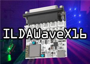
ILDAWaveX16 is an open-source, high-resolution, wireless laser DAC with SD-card playback, network control, and ILDA output.Traditional laser DACs are often expensive, proprietary, or limited in flexib...
ILDAWaveX16 | StanleyProjects.com
916
0
3
StanleyProjects
StanleyProjects
SLOVAKIA
27
0
For personal use, not for resale!Check new super simple messengers based on All in one Heltec TRACKER as main brain.Same firmware, same simplicity as TrackSenger, just another switches now w...
TrackSenger - Standalone - Armachat - Meshtastic WiFi-LoRa-BT-GPS
1527
0
3
Bobricius Bobricius
Bobricius Bobricius
SLOVAKIA
36
0
1
2
3
4