|
|
Resistor 10KΩ |
x 1 | |
|
|
2-pin Header |
x 1 | |
|
|
Harwin D01-9923246 32-way SIL pin headerHarwin Inc.
|
x 1 |

|
KiCad 9.0 |
2732-to-2764 Daughterboard
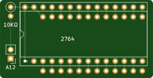
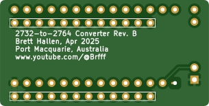
A very simple board designed to allow two different BIOS ROMs to be installed in the Osborne 1 computer. It can also be used anywhere that a 2732 (4KByte) EPROM needs to be replaced with a 2764 (8KByte) EPROM.
I could've made the board a little bit smaller by using a surface-mount pull-up resistor but I opted for simplicity for everyone by using all though-hole parts.
Background why I designed this board:
The standard BIOS ROM for the Osborne 1 is a 4KByte 2732 which is 24 pins.
Using an 8KByte 2764 EPROM allows one to have two different BIOS installed (i.e. official Osborne and 3rd party OZROM) that can be switched via the A12 address pin.
Alternatively, it allows you to replace an older BIOS using a 2764 EPROM if you can't program or source 2732 EPROMs.
By default the A12 address pin is pulled HIGH by the 10KΩ resistor (so default is upper ROM address range 0x1000 to 0x1FFF) or can be switched to LOW via a strapping or SPST switch connected to the A12 pin header (so lower ROM address range 0x0000 to 0x0FFF). This grounds the A12 address line.
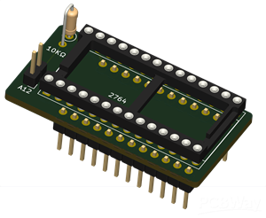
The sample picture shows the 2764 EPROM soldered directly the board. You can use an IC socket instead if you have room (there is room in the Osborne 1) and this was how I originally tested it. Once I confirmed it was working I created a second one soldered directly to the board so it looks more "slimline".
2732-to-2764 Daughterboard
*PCBWay community is a sharing platform. We are not responsible for any design issues and parameter issues (board thickness, surface finish, etc.) you choose.

Raspberry Pi 5 7 Inch Touch Screen IPS 1024x600 HD LCD HDMI-compatible Display for RPI 4B 3B+ OPI 5 AIDA64 PC Secondary Screen(Without Speaker)
BUY NOW- Comments(0)
- Likes(5)
-
 Ruud Broers
Jul 18,2025
-
 Bernhard Roth
May 15,2025
-
 Juan VM
Nov 16,2024
-
 pmcfadin
Nov 01,2024
-
 (DIY) C64iSTANBUL
Sep 17,2024
- 0 USER VOTES
- YOUR VOTE 0.00 0.00
- 1
- 2
- 3
- 4
- 5
- 6
- 7
- 8
- 9
- 10
- 1
- 2
- 3
- 4
- 5
- 6
- 7
- 8
- 9
- 10
- 1
- 2
- 3
- 4
- 5
- 6
- 7
- 8
- 9
- 10
- 1
- 2
- 3
- 4
- 5
- 6
- 7
- 8
- 9
- 10
 More by Brett Hallen
-
 Exelvision ROM Cartridge (4Mbit)
The French Exelvision computer from the 1980s was a bit of an oddity as it was the only computer to ...
-
 2732-to-2764 Daughterboard
A very simple board designed to allow two different BIOS ROMs to be installed in the Osborne 1 compu...
-
 8080A CPU Breakout Board for Logic Analyser/Analyzer
A logic analyser is an invaluable tool for diagnosing computer faults but I find myself hesitant to ...
-
 Exelvision ROM Cartridge (32KB)
The French Exelvision computer from the 1980s was a bit of an oddity as it was the only computer to ...
-
 Matra Alice/Tandy TRS-80 MC-10 Internal 8KB RAM Upgrade
BackgroundThis design is based on the work that Daniel Tufvesson documented on his blog for the Tand...
-
 BBC Master Compact Floppy Interface Board
The BBC Master Compact (MC) computer has a separate unit (Disk Drive & Monitor Stand) that house...
-
ARPS-2 – Arduino-Compatible Robot Project Shield for Arduino UNO
378 0 0 -
A Compact Charging Breakout Board For Waveshare ESP32-C3
726 3 6 -
AI-driven LoRa & LLM-enabled Kiosk & Food Delivery System
703 2 0 -
-
-
-
ESP32-C3 BLE Keyboard - Battery Powered with USB-C Charging
922 0 1 -
-
mammoth-3D SLM Voron Toolhead – Manual Drill & Tap Edition
782 0 1 -
-
AEL-2011 Power Supply Module
1535 0 2


