Although sheet metal bending appears to be a simple manufacturing process, many production issues—including cracking, hole distortion, tooling interference, excessive springback, and assembly failures—can often be traced back to design-stage mistakes.
Through PCBWay's Sheet Metal Design Service, our engineers regularly help customers optimize bending structures before fabrication, reducing production risks, minimizing manufacturing costs, and improving overall product quality.
Sheet metal bending is a forming process in which force is applied to a metal sheet using a press brake and tooling, causing plastic deformation and transforming a flat sheet into a three-dimensional structure. Due to its high efficiency, excellent structural strength, weld-free assembly capability, and suitability for mass production, sheet metal bending is widely used in communication cabinets, industrial control enclosures, consumer electronics brackets, medical equipment housings, and many other applications.
The quality of a bending design directly affects manufacturing yield, dimensional accuracy, appearance quality, and production cost. Poorly designed bends can result in cracking, distortion, hole deformation, tooling interference, and assembly issues, often leading to rework, scrap, longer lead times, and increased manufacturing expenses.
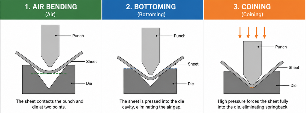
In modern sheet metal manufacturing, three primary bending methods are commonly used: Air Bending, Bottoming, and Coining. Each offers different levels of precision, cost, and production efficiency.
In air bending, the sheet only contacts the punch and die at specific points while the material remains suspended between them. The bend angle is controlled by punch penetration depth.
Advantages:
Limitations:
Bottoming forces the sheet metal into full contact with the die cavity, reducing springback and improving angle consistency.
Advantages:
Limitations:
Coining applies extremely high pressure to plastically deform the material at the bend line, virtually eliminating springback.
Advantages:
Limitations:
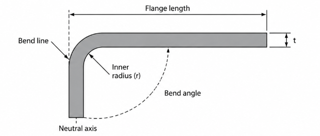
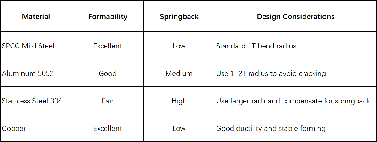
The bend radius refers to the inside radius formed after bending and is one of the most critical parameters in sheet metal bending design. It directly affects cracking resistance, springback behavior, and overall forming quality.
A bend radius that is too small may overstretch the outer fibers of the material and cause cracking, while an excessively large radius may increase springback and dimensional variation.
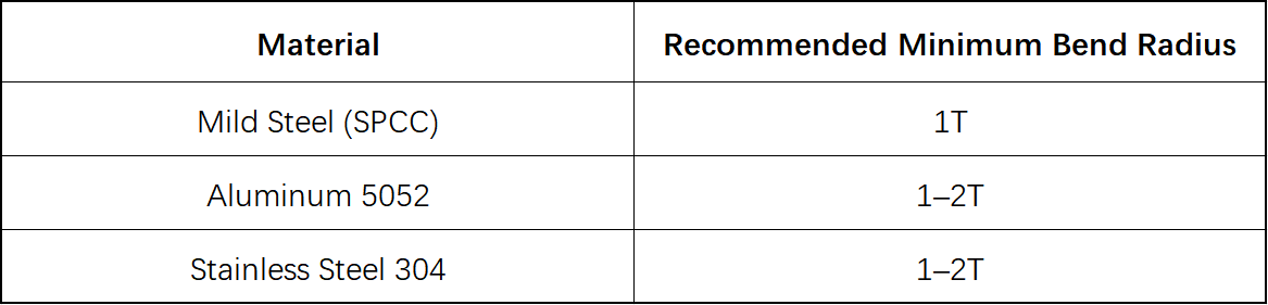
Recommended minimum inside bend radius (T = material thickness):
During bending, the inner surface of the material is compressed while the outer surface is stretched. Between these regions lies the Neutral Axis, which experiences neither compression nor tension. The location of the neutral axis changes depending on material type, thickness, and bend radius, making it a critical factor in flat pattern calculations.
Three key parameters are derived from the neutral axis concept:
K-Factor:Defines the position of the neutral axis within the material thickness and directly influences flat pattern accuracy.
Bend Allowance (BA):The length of the neutral axis through the bend region.
Bend Deduction (BD):The difference between theoretical flat dimensions and finished bent dimensions, used to calculate accurate blank sizes.
Bend Allowance is commonly calculated using:
BA = θ × (R + K × T) × π / 180
Where:
Accurate bend allowance calculations are essential for achieving correct flat pattern dimensions and reducing costly manufacturing errors.
Design for Manufacturability (DFM) ensures that a part can be produced efficiently using standard tooling and manufacturing processes. The following sheet metal design rules are among the most important guidelines for successful production.
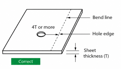
Holes, slots, and cutouts placed too close to a bend line are among the most common design mistakes.
During bending, stress concentrations near these features may cause deformation, tearing, or dimensional inaccuracies.
Recommended guideline:
Feature edge to bend line distance ≥ 4T
Good Design:
Poor Design:
A flange that is too short cannot be properly supported by standard press brake tooling.
Recommended minimum flange length:
Minimum Flange Length = Bend Radius + 4T
Insufficient flange height may lead to incomplete forming, angular inaccuracies, or manufacturing failure.
Multiple bends located too closely together can cause tooling interference during forming.
Proper spacing should be maintained to:
Reverse bends with insufficient spacing often require special tooling and multiple setups.
When designing Z-bends:
Without proper bend reliefs, stress concentrations at corner intersections may cause tearing, warping, or deformation.
Common relief types include:
Rectangular Relief
Round Relief
Cracking is common when:
Springback occurs because metal materials elastically recover after forming.
General trend:
Typical solutions include overbending, bottoming, and optimized bend radius selection.
Hole distortion is typically caused by insufficient distance between holes and bend lines.
Following the 4T rule can effectively eliminate this issue.
Scratches may result from:
Protective films and polished tooling surfaces can significantly improve cosmetic quality.
Using a consistent bend radius throughout a design reduces tooling changes and improves production efficiency.
Reducing bend count lowers processing time, setup complexity, and dimensional accumulation errors.
Avoid special bend angles, narrow flanges, and deep-forming features whenever possible.
Reducing part flipping and secondary setups improves throughput and consistency.
Hem bends fold the sheet edge back onto itself to eliminate sharp edges and improve rigidity.
These features create offsets for assembly clearance and component positioning.
Features such as louvers, embosses, beads, and ribs can significantly improve stiffness without increasing material thickness.
✅️ Bend radius follows material requirements
✅️ Hole-to-bend distance ≥ 4T
✅️ Corner relief added where necessary
✅️ Minimum flange length verified
✅️ Bend sequence manufacturable
✅️ Springback considered
✅️ Standard tooling used
✅️ DFM review completed
The essence of successful sheet metal bending design lies in understanding material behavior and following proven manufacturing guidelines. Most production defects, excessive costs, and schedule delays can be prevented through proper DFM practices during the design stage.
At PCBWay, we provide complete sheet metal fabrication, enclosure manufacturing, and mechanical design services—from DFM review and prototype validation to low-volume and mass production. By applying these sheet metal bending design guidelines early in the development process, engineers can improve manufacturability, reduce costs, and accelerate product development.


