Sheet metal fabrication is widely used for enclosures, brackets, chassis, and industrial housings through processes such as cutting, bending, welding, and surface finishing. Although many designs look correct in CAD, production often reveals problems such as cracking, deformation, assembly interference, and increased manufacturing cost due to poor manufacturability considerations.
CAD Modeling and Basic Design Errors
Error 1: Submitting a Solid 3D Model Without Proper Bend Information
Manufacturers may not be able to accurately identify bend locations, flat pattern dimensions, or forming sequences, leading to inaccurate quotations, dimensional deviations, or even manufacturing failure.
Recommendations:
- Use dedicated sheet metal modeling tools when creating the design
- Clearly define bend lines, bend radii, and bend directions
- Keep material thickness consistent throughout the part
- Provide flat pattern drawings for fabrication and bend verification
Error 2: Ignoring Bend Radius and K-Factor Compensation
During bending, the inner side of the material is compressed while the outer side is stretched. Incorrect bend calculations can result in inaccurate flat lengths and significant dimensional deviations after forming.
Recommendations:
- A common default inside bend radius is 0.030in (0.762mm)
- Outside bend radius = inside radius + material thickness
- Use consistent bend radii throughout the same part to reduce tooling changes and manufacturing cost
- Set the correct K-factor in CAD based on material type and thickness
Critical Bending and Feature Placement Errors
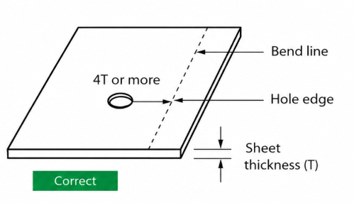
Error 3: Placing Holes, Slots, or Bosses Too Close to Bend Lines
Material near the bend area undergoes severe deformation during bending. Features placed too close to bend lines may become distorted, crack at the edges, or lose structural strength.
Recommendations:
- Follow the 4T rule: minimum distance from feature edge to bend line ≥ 4 × material thickness
- Add relief slots if the feature cannot be relocated
- Keep slot arrays and elongated holes away from bend zones whenever possible
Error 4: Missing Bend Relief Slots
When a bend line intersects directly with an edge, the material lacks enough space to deform properly, often causing tearing, bulging, or bend angle distortion.
Recommendations:
- Add bend relief slots or cutouts at bend terminations
- Recommended relief width ≥ material thickness
- Recommended relief depth ≥ material thickness + bend radius
- Relief slots help reduce stress concentration and improve corner quality
Error 5: Flanges That Are Too Short
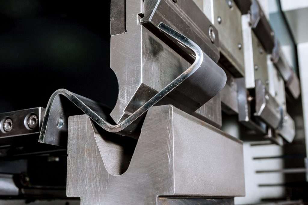
Press brake tooling requires adequate support during bending. Extremely short flanges may slip, deform, or fail to maintain proper bend positioning.
Recommendations:
- Minimum flange length should generally be ≥ 2 × material thickness + bend radius
- Thin aluminum and thick stainless steel may require different minimum values depending on tooling capability
- Replace extremely short bends with welded or riveted assemblies when necessary
Error 6: Bend Spacing Too Tight or Incorrect Bend Sequence
Closely spaced bends or conflicting bend directions can create part interference or tooling collisions during forming.
Recommendations:
- Maintain sufficient spacing between bends for tooling clearance
- Simulate the bend sequence for complex parts
- Follow common forming practices such as “inside bends first, outside bends later”
- Split enclosed box structures into multiple parts when necessary
Error 7: Improper U-Channel Proportions
Poor width-to-height ratios in U-shaped channels can reduce structural rigidity and create forming limitations due to tooling access.
Recommendations:
- Maintain a width-to-height ratio of at least 2:1 whenever possible
- Use welding or riveting for extremely narrow channel structures instead of relying on single-step bending
Material, Surface Finish, and Hardware Errors
Error 8: Choosing Materials Unsuitable for the Application Environment
Using standard cold-rolled steel in outdoor or humid environments may lead to rapid corrosion. Incorrect material selection can also affect conductivity, strength, or thermal performance.
Recommendations:
- Consider corrosion resistance, strength, formability, conductivity, and cost together
- Use galvanized steel, stainless steel, or aluminum alloys in corrosive environments
- Select copper or aluminum for conductive applications
Error 9: Incorrect or Missing Surface Finish Selection
Surface treatment affects not only appearance, but also corrosion resistance and manufacturing compatibility. Some finishes may create processing risks during welding or assembly.
Recommendations:
- Protective finishes: galvanizing, anodizing, chromate conversion coating
- Decorative finishes: powder coating, silk screening
- Perform welding before galvanizing or similar finishing processes
Error 10: Missing or Unclear Hardware Specifications
PEM fasteners, studs, and threaded inserts without clear specifications may cause assembly errors, missing hardware, or production delays.
Recommendations:
- Clearly define PEM hardware models and installation locations in assembly drawings
- Use standardized hardware library models whenever possible
- Add positional tolerances for critical mounting features
Welding and Tolerance Issues
Error 11: Unrealistic Welding Requirements
Enclosed cavities, inaccessible weld areas, or excessively thin materials can make welding difficult or impossible.
Recommendations:
- Recommended minimum weldable thickness ≥ 0.040in (1.016mm)
- Place weld seams in accessible areas whenever possible
- Use standard welding symbols instead of relying only on visual references
Error 12: Excessively Tight Tolerances or Tolerance Stack-Up
Applying unnecessarily tight tolerances to non-critical dimensions increases manufacturing cost and reduces production yield. Tolerance accumulation across multiple parts can also create assembly issues.
Recommendations:
- Apply strict tolerances only to critical mating or locating features
- Use standard economical tolerances for non-critical dimensions
- Perform tolerance stack-up analysis during assembly design
General Sheet Metal Box Design Best Practices
- Collaborate with manufacturers early to confirm tooling capability and standard processes
- Standardize hole sizes, flange dimensions, hardware, and bend radii whenever possible
- Simplify structures and eliminate unnecessary complex geometry
- Use sheet metal simulation tools for flat pattern and bend interference verification
- Clearly specify materials, thickness, bends, hardware, surface finishes, and welding requirements
Good sheet metal design is not only about creating a structure that works in CAD, but also ensuring it can be manufactured efficiently and reliably. By considering bending limitations, material behavior, welding accessibility, and tolerance control early in the design stage, engineers can significantly reduce production risks, rework, and overall manufacturing cost.
PCBWay design service helps customers optimize sheet metal enclosures and box designs through DFM review, structural analysis, and manufacturing-focused engineering support, helping turn concepts into production-ready products more efficiently.


