In electronic product development, enclosure design is often underestimated. Even when the PCB functions correctly, poor enclosure design can still lead to overheating, assembly interference, insufficient waterproofing, cable stress, or failed outdoor reliability tests.
A well-designed enclosure is not only a protective shell, but also a critical part of thermal management, structural reliability, manufacturability, and user experience.
Core Design Requirements: Defining Application Needs and Compliance Standards
The first step in enclosure design is not CAD modeling, but defining the “application scenario + protection level + functional requirements” to avoid repeated redesigns later in development.
Protection Standards in Enclosure Design
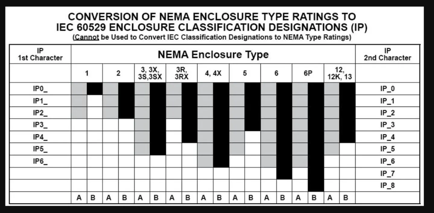
Protection ratings determine the enclosure’s materials, structure, and manufacturing process. Indoor and outdoor applications require different protection standards, with NEMA and IP being the two most widely used systems.
NEMA Standards (National Electrical Manufacturers Association) focus on environmental protection for industrial applications:
- NEMA 1: Basic indoor protection against light dust and accidental contact, commonly used for indoor control equipment;
- NEMA 3: Outdoor protection against dust, rain, snow, and ice formation;
- NEMA 4 / 4X: Industrial waterproof protection, with 4X adding corrosion resistance for coastal or chemical environments;
- NEMA 12: Enhanced indoor dust and moisture protection for industrial equipment.
IP Ratings (IEC 60529) focus specifically on dust and water ingress protection:
- IP54: Limited dust protection and splash resistance;
- IP65: Fully dustproof and resistant to water jets;
- IP67: Temporary immersion protection for harsh outdoor environments.
In industrial applications, designers should also consider standards such as UL 50/508A for safety compliance and IEC 61439 for mechanical strength and thermal performance.
Functional Requirements in Mechanical Design
Before starting enclosure design, key functional requirements should be clearly defined:
- Internal Components: PCB dimensions, mounting holes, connector locations, and heat-generating components requiring thermal structures;
- Environmental Conditions: Indoor or outdoor use, operating temperature range, humidity, corrosion exposure, and required dust protection level;
- Assembly and Maintenance: Frequency of opening the enclosure, mounting method (wall-mounted, handheld, desktop), and cable management requirements;
- Manufacturing Process: Injection molding for mass production or 3D printing for prototyping, as manufacturing methods directly affect wall thickness and tolerance design.
Material Selection: Balancing Performance, Cost, and Environment
Material selection directly impacts protection performance, durability, thermal behavior, and manufacturing cost. Common enclosure materials can generally be divided into plastics and metals.
Plastic Enclosure Materials: Cost-Effective for Indoor Applications
Plastic enclosures are lightweight, easy to mold, and cost-efficient, making them suitable for NEMA 1 or NEMA 12 applications.
- ABS: Balanced mechanical performance and chemical resistance, widely used in consumer electronics. However, long-term UV exposure may cause aging outdoors;
- Polycarbonate (PC): High impact resistance, heat resistance, and UV stability, suitable for both indoor and outdoor applications;
- PC + ABS Blends: Improved impact resistance and low-temperature performance for premium indoor devices;
- ASA/PC Blends: Excellent weather resistance, thermal stability, and chemical resistance for outdoor use without additional coating.
Metal Enclosure Materials: Preferred for Industrial and Outdoor Equipment
Metal enclosures provide superior strength, corrosion resistance, and thermal conductivity, making them ideal for NEMA 3/4/4X applications.
- Aluminum Alloy: Lightweight and corrosion-resistant, often anodized for improved durability. Common grades include 5052 for sheet metal and 6061 for CNC machining;
- Stainless Steel: High strength and exceptional corrosion resistance, ideal for humid or chemically aggressive environments;
- Cold-Rolled Steel: Low-cost with good rigidity, suitable for indoor powder-coated applications;
- Galvanized Steel: Zinc-coated low-carbon steel offering better moisture resistance than standard cold-rolled steel.
For 3D printed enclosure prototypes, material selection directly affects strength, thermal resistance, and durability. PLA is suitable for rapid validation, while ABS, PETG, and Nylon are often preferred for functional or mechanical structures. More details can be found in How to Choose the Material for 3D Printing.
Structural Mechanical Design for PCB Enclosures
Structural design directly affects manufacturing yield, assembly reliability, and long-term durability. Key focus areas include wall thickness, tolerances, reinforcement structures, and assembly methods.
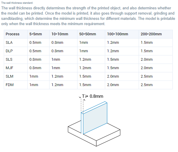
Wall Thickness Design
Uneven wall thickness can cause sink marks in injection molding or cracking in 3D printing.
- Uniform Wall Thickness: Plastic injection-molded enclosures typically use 1.5–2.5 mm walls, while metal enclosures commonly use 1.0–2.0 mm. Excessively thick walls may cause sink marks and uneven cooling during injection molding, while overly thin walls can reduce structural rigidity and increase warpage risk;
- 3D Printing Requirements: For FDM printing, the minimum wall thickness is generally ≥0.8 mm or at least twice the nozzle diameter; You can refer to PCBWay's wall thickness requirements to assist you with your wall thickness design.
- Rounded Corners and Fillets: Adding fillets above 0.1 mm reduces stress concentration and improves molding flow and print quality.
Clearance and Tolerance Design
Manufacturing tolerances and thermal expansion require sufficient clearance between components and enclosure structures.
- PCB-to-Wall Clearance: Maintain at least 0.5 mm spacing to avoid assembly interference;
- Connector Openings: Circular openings should be 0.2–0.3 mm larger than connector diameters, while rectangular openings should reserve approximately 1 mm clearance per side;
- Snap Fits and Hinges: Moving structures generally require 0.5–1 mm clearance to prevent sticking or looseness.
Reinforcement Structures: Ribs, Gussets, and Bosses
Thin-wall structures require reinforcement to improve stiffness and durability.
- Ribs: Internal reinforcement ribs should be approximately 1/2 to 2/3 of the wall thickness to reduce deformation;
- Gussets: Triangular support structures distribute stress at corners and large flat surfaces;
- Bosses: Screw bosses should be reinforced with ribs to prevent cracking during assembly. Plastic screw holes are typically designed about 0.3 mm smaller than the screw diameter for proper thread engagement.
For 3D printed enclosure prototypes, thread and joint design greatly affect assembly reliability. Compared with directly printed threads, heat-set inserts provide better durability and torque resistance, especially for repeated assembly. Proper snap-fit and boss design can also reduce cracking and improve structural strength. More detailed guidelines can be found in Designing Threads, Inserts & Joints for 3D Printing
Assembly and Maintenance Design
The enclosure structure should balance structural stability and serviceability.
- Fastening Methods: Screw fastening is preferred for mass production, while snap fits or adhesives may be suitable for prototypes;
- Cable Management: Cable entry points should include strain relief or protective sleeves to prevent cable damage;
- Thermal Management: Heat-generating devices may require ventilation slots, fan mounting locations, or heatsink provisions while maintaining the required IP protection level.
Mechanical Design Tools: From 3D Modeling to DFM Validation
Efficient enclosure design requires collaboration between ECAD and MCAD systems to reduce iteration cycles and manufacturing risks.
- 3D Modeling and Visualization: Tools such as OrCAD X and SolidWorks allow engineers to visualize PCB and enclosure assemblies and identify mechanical interference early;
- Cross-Domain Collaboration: Exporting models in STEP format enables seamless integration between PCB and mechanical design workflows;
- DFM Validation: Design-for-manufacturing analysis helps identify wall thickness inconsistencies, insufficient draft angles, and molding risks before production.
Many enclosure issues such as warping, weak thin walls, and cracking around screw bosses often appear during 3D printing rather than in CAD models. Optimizing wall thickness, print orientation, and support structures early can improve prototype reliabilit. More detailed analysis can be found in 3D Printing Inquiry Failure Problem.
Common PCB Mechanical Design Mistakes
Several common enclosure design mistakes can lead to costly redesigns or product reliability issues:
- Ignoring connector tolerances
- Neglecting cable bending radius requirements
- Placing ventilation holes near water exposure areas
- Insufficient spacing between the PCB and enclosure walls
- Overly thick bosses causing sink marks
- Ventilation openings reducing IP protection levels
- Poor grounding design in metal enclosures
- Ignoring EMI shielding requirements
EMI and EMC performance are critical in high-speed and industrial electronic products.
- Metal enclosures naturally provide electromagnetic shielding
- Plastic enclosures may require conductive coatings or shielding paint
- Gaps between enclosure seams can become EMI leakage paths
- Large ventilation openings may increase electromagnetic radiation
- Proper grounding improves shielding effectiveness
- EMI gaskets can reduce leakage around enclosure joints and removable panels
Conclusion
In practical projects, enclosure design must balance protection level, thermal performance, manufacturability, cost, and assembly efficiency. Early collaboration between PCB and mechanical design teams can significantly reduce redesign cycles and improve first-pass success rates.
With extensive experience in PCB and hardware development, PCBWay Design Service helps engineers optimize enclosure compatibility, structural layout, and manufacturability from the early design stage.


