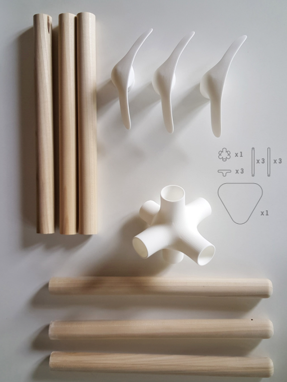
In 3D printing, the build volume of most printers limits the maximum size of parts that can be printed as a single piece. Large models often need to be split into several smaller sections for separate printing. After printing, the connections between these parts become critical for ensuring structural integrity and functional reliability.
These joints not only hold components together but also handle load transfer, mechanical interaction, and even motion between parts. Among all connection methods, threads, inserts, and mechanical joints are the three key design elements that define the reliability of 3D printed parts.
This guide will show you how to design threads, inserts, and joints for 3D printing so your models are both strong and functional — improving your overall 3D printing success rate.
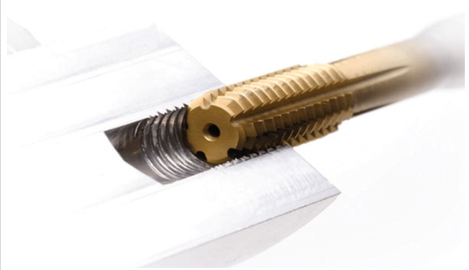
For small internal threads such as M5 or smaller, direct 3D printing threads is challenging. The nozzle diameter (commonly 0.4 mm) and layer resolution make it difficult to reproduce fine thread profiles — resulting in weak, inaccurate threads. Moreover, support residues in the internal grooves are hard to remove.
Hole Diameter and Tolerance:
It’s generally not recommended to print internal threads smaller than M5 (or 1/4 inch). For more precise applications, start from M6 and above.
Due to FDM’s arc effect and thermal shrinkage, FDM thread design for 3D printing typically requires oversizing the internal hole by 0.1–0.3 mm beyond the theoretical value. SLA printers can achieve better accuracy and may need smaller adjustments.
Printing Orientation:
Always print internal threads vertically. The thread’s cross-section lies in the XY plane, where layer bonding is strongest — effectively resisting shear forces during tightening.
Post-processing:
Given the limitations of directly printing small threads, post-processing is essential. For reliable 3D printing threads, small-diameter internal holes should be tapped or fitted with threaded inserts (via heat or ultrasonic embedding) to ensure precision and strength.
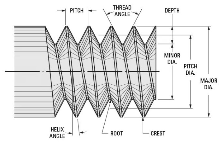
External threads demand even higher accuracy since the outer diameter and pitch must precisely match standard nuts. The crests of FDM-printed threads are fragile, often chipping or wearing down under torque.
Dimensional Compensation:
Design the external diameter 0.1–0.2 mm larger to compensate for shrinkage and the “stair-step” layer effect.
For FDM printing, keep the external thread diameter ≥ 3–4 mm and the pitch ≥ 0.8 mm.
For SLA printing, smaller threads are possible due to higher resolution.
Orientation and Layer Height:
Print vertically to ensure smooth layer stacking and better thread tolerance and accuracy.
Use a layer height ≤ 0.2 mm for FDM and ≤ 0.05 mm for SLA to achieve clean thread profiles.
In summary, when doing 3D printing thread design, prioritize vertical printing and consider M6 or larger threads. For critical joints, use threaded inserts; for non-load-bearing parts, tapping is a cost-effective option. Directly printed threads are best reserved for light-duty, aesthetic, or low-torque applications.
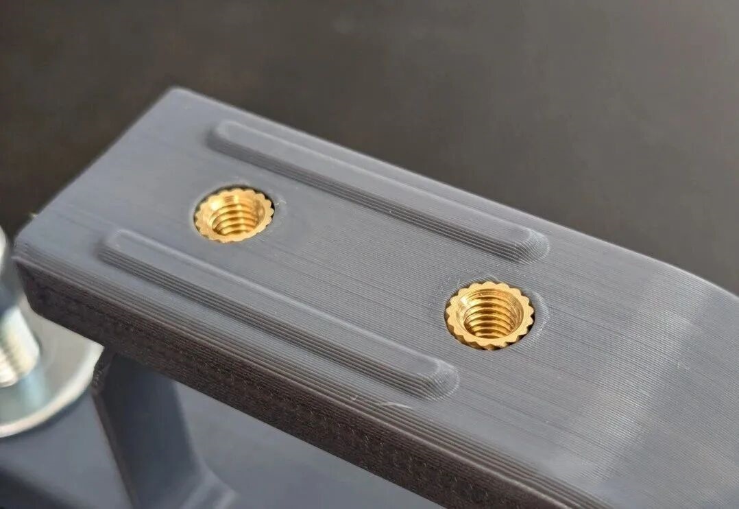
3D printing inserts are far stronger than printed plastic threads. They resist stripping, tolerate higher torque, and can withstand repeated assembly cycles — making them essential for reliable mechanical fastening.
Hot Inserts:
Heated with a soldering iron or thermal press, the insert melts surrounding plastic as it’s pressed into a predesigned hole. The molten polymer then solidifies, filling the insert’s knurled grooves, forming a robust mechanical and chemical bond.
Cold Inserts:
Pressed at room temperature using mechanical force. It relies on tight interference between the hole and the insert’s knurled surface.
Hole Size:
Because FDM-printed holes tend to shrink, the hole diameter should be 0.1–0.2 mm smaller than the insert’s outer diameter for hot embedding, or 0.05–0.1 mm smaller for cold embedding.
Wall Thickness:
The distance from the insert’s outer wall to any nearby edge should be ≥ 1.5× the insert’s diameter. This prevents wall cracking and provides sufficient support against radial pressure.
Best materials for 3D printing inserts: ABS, Nylon, PETG, and PC — all of which tolerate heat and mechanical stress.
Avoid using inserts with PLA, which is brittle and prone to cracking under stress or heat. If unavoidable, increase wall thickness and use hot embedding carefully.
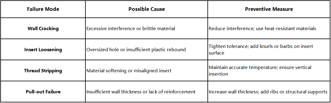
In short, successful insert design for 3D printing depends on precise hole size, adequate wall thickness, and the right embedding technique.
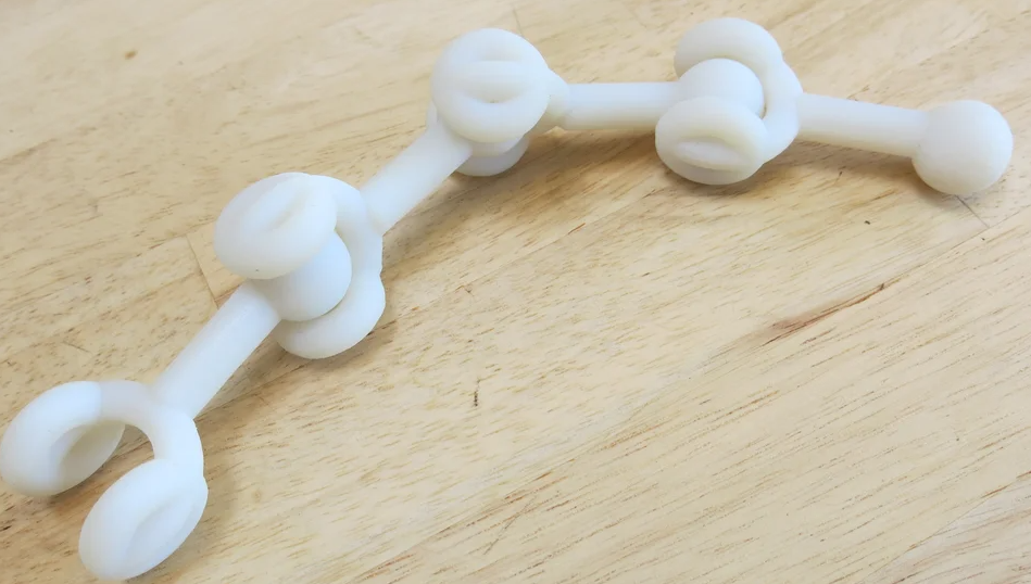
Mechanical Joints:
Use threads, snap-fits, or pins to create detachable, high-strength 3D printing mechanical connections.
Adhesive Joints:
Bonded with cyanoacrylate, epoxy, or specialized plastic glues.
Choose mechanical joints if you need reassembly or maintenance.
Choose adhesive bonding in 3D printing if you want a permanent, seamless, high-strength joint.
For hybrid strength, use threaded inserts + adhesive bonding.
Snap-fit Joints:
A classic quick-assembly structure utilizing elastic deformation. Here are some tips for snap-fit joints:
Detachable Joints:
Employ screws, pins, or slide-lock structures for repeated assembly.
Align the assembly direction with the layer orientation to improve load-bearing joint design strength.
Joint reliability in 3D printing joint design depends on managing loads — tensile, compressive, shear, or torsional.
To ensure even stress distribution in 3D printed parts:
To improve stiffness and strength without extra mass:
Proper reinforcement and stress management make your 3D printing joints both durable and visually refined.
To enhance 3D printed part reliability, design is the foundation. Successful parts come from a balance of design and process—considering material, printing direction, and tolerance. Only then can 3D printing threads, 3D printing inserts, and 3D printing joints achieve strong and durable connections.
Feel free to ask us if you have any question.


