

SOMA, a desk robot arm with printed cycloidal joints
SOMA: a desk robot arm with printed cycloidal joints
Overview
SOMA is a desk-scale robot arm I'm building: six joints plus a parallel-jaw gripper, made to be driven by software (a script or an agent) over a documented serial protocol and Python API. The structure is 3D-printed in PETG-CF, and the two heavily loaded joints, the shoulder (J2) and elbow (J3), run on printed 40:1 cycloidal gearboxes driven by brushless motors. Those are the joints that normally push a desktop arm onto expensive metal gearboxes.
To be clear up front: SOMA is not built yet. The design is complete and has been checked in CAD and simulation, but nothing has been printed or bought. Every image below is a render or a diagram made from the design files, not a photo.
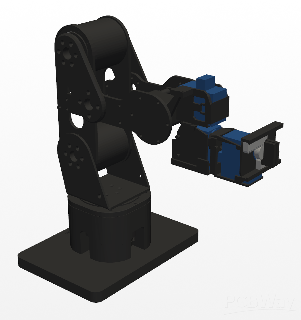
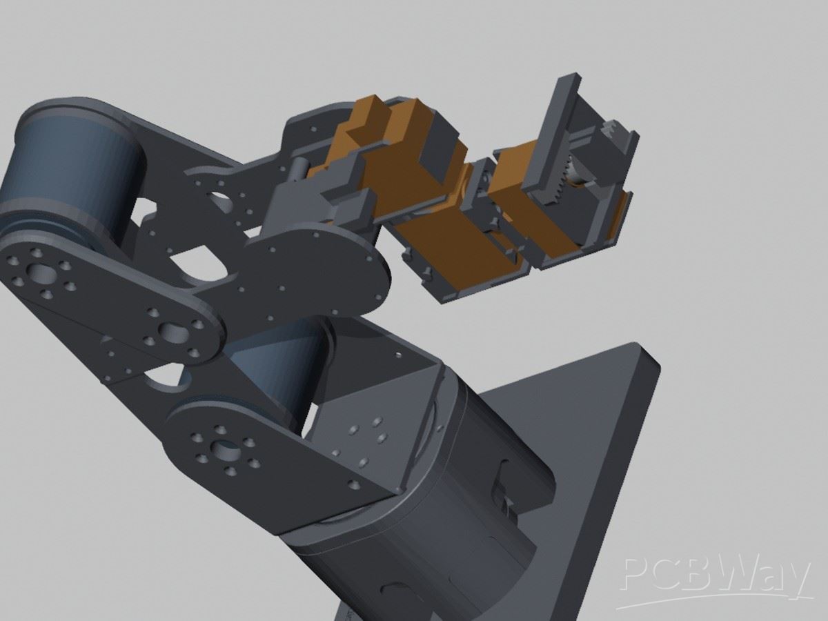
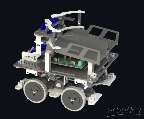
SOMA full assembly in its home pose, rendered from the current CAD assembly (final/out/assembly.stl). Dark grey = printed PETG-CF, blue = Feetech servos. Render only; the arm is not built yet.
Key numbers from the repo:
- 6 joints + gripper, about 0.36 m maximum reach with the tool level
- Rated payload 0.25 kg, with about 0.35 kg peak headroom
- About 1.1 kg modelled arm mass on a 140 × 200 mm desk-mount base
- Every printed part is 200 mm or smaller and fits a Bambu A1 bed; the full print list is about 1.2 L, roughly one 1 kg spool
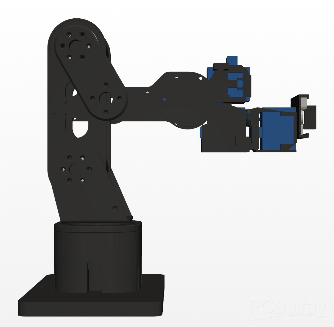
Side view of the same assembly in its home pose, showing the printed link plates and the wrist reaching forward. Render only.
Why I'm building it
Cheap open-source arms tend to be fragile, and the stronger ones jump straight to metal gearboxes and a much higher price. I want an arm that sits in between: slow and light-duty, but honest about what it can lift and safe to have on a desk. That meant designing the payload rating around checked numbers rather than hopeful ones, and building the safety limits into both the firmware and the hardware.
The joint layout is based on Seeed's open-source reBot-DevArm (CERN-OHL-W-2.0), at about 0.48× scale, re-engineered around Feetech bus servos and the printed actuators.
Mechanical design
The whole arm is parametric. The mechanical CAD is build123d Python, so every part can be regenerated from code. All structural parts are PETG-CF printed on a Bambu A1, which is why every part is kept under 200 mm.
The actuator map:
Joint | Function | Actuator
J1 | base yaw | Feetech STS3250
J2 | shoulder | Tarot 4008 + 40:1 printed cycloidal, B-G431B-ESC1
J3 | elbow | Tarot 4008 + 40:1 printed cycloidal, B-G431B-ESC1
J4 | wrist pitch | Feetech STS3250 (printed cradle + second bearing)
J5 | wrist yaw | Feetech STS3215
J6 | tool roll | Feetech STS3215
Gripper | parallel jaw | Feetech STS3215, rack and pinion, 25 mm stroke
J2 and J3 also carry one-way torsion balance springs (Springmasters 471671) that take load off the motors in forward poses.
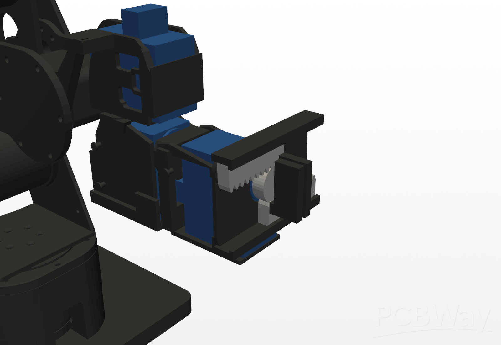
Close-up of the current (R9) wrist and gripper: STS servos for wrist pitch, yaw and roll, and the rack-and-pinion parallel gripper with a steel pinion and printed racks. Render only.
The cycloidal actuators are the core of the design. Each module has two 4.25 mm PETG-CF cycloidal discs (Ø44.7 mm) rolling on hardened ISO 8734 steel dowels: 41 Ø3×10 ring pins, 6 Ø3×12 output pins and 3 Ø4×8 locating pins per module. The housing is about 57 × 57 × 54 mm. A Tarot TL2955 4008 330KV motor drives the eccentric hub, an ST B-G431B-ESC1 running SimpleFOC controls it over CAN, and an AS5600 magnetic encoder reads the motor shaft.
The disc profile uses a near-zero flank clearance (0.01 mm), which spreads the load over about 10 of the 41 pins instead of two or three. That is below normal FDM tolerance, so the build starts with a printed calibration coupon, selective fitting of the pins and a run-in for each module.
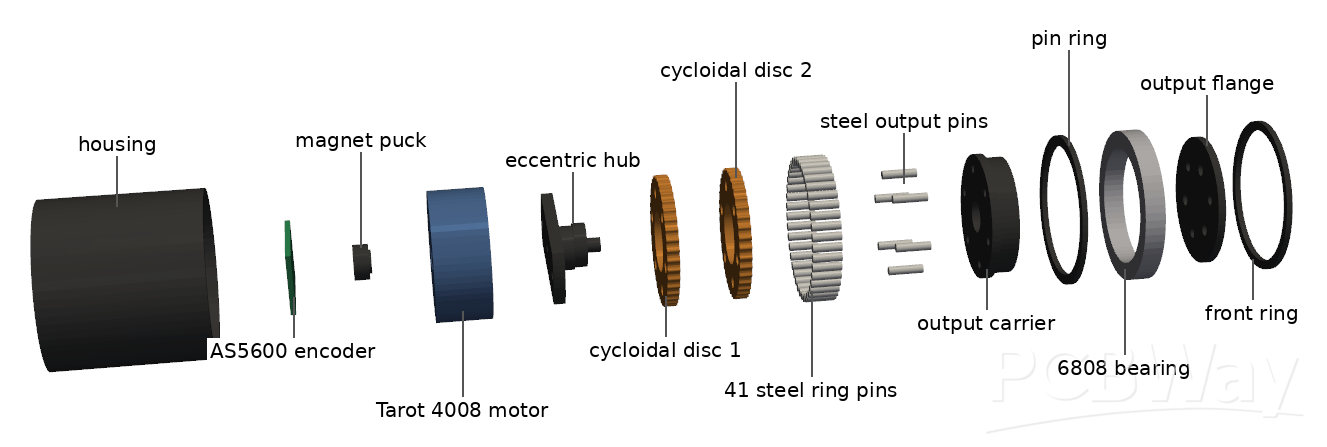
Exploded view of one J2/J3 cycloidal actuator, rendered from the cyclo4/out CAD files: housing, AS5600 encoder, magnet puck, Tarot 4008 motor, eccentric hub, two printed cycloidal discs, 41 steel ring pins, steel output pins, output carrier, pin ring, 6808 bearing, output flange and front ring. The small bearings, magnet and locating dowels are hidden for clarity.
Verification
The arm hasn't been built, but it has been checked end to end in analysis. The full report is FULLCHECK.md in the repo. The verdict is "READY TO ORDER at 0.25 kg".
- Interference: the 73-part posed assembly has zero undeclared intersections at home, and per-joint sweeps at 2.5° steps pass, with only documented exceptions (the printed yaw stop at ±152.5°, poses below the table, and tiny grazes at extreme folds).
- Torque: a 29,653-pose sweep at 0.25 kg puts the worst joint at 83% of its firmware cap (J2, 2.481 N·m). The workspace payload bound is 0.385 kg.
- Strength: converged per-part CalculiX FEA on every load-bearing printed part, with bolted and pinned interfaces, passes all four PETG-CF allowables at 0.25 kg. The lowest converged main-structure margin is SF 3.22. One borderline is disclosed: the w_link5 lip is SF 2.56 against the 8 MPa shear allowable, but SF 1.96 against the most conservative 6.1 MPa bound.
- Limits I'm not claiming: 0.38 kg and 0.5 kg ratings are not met, and the report says so.
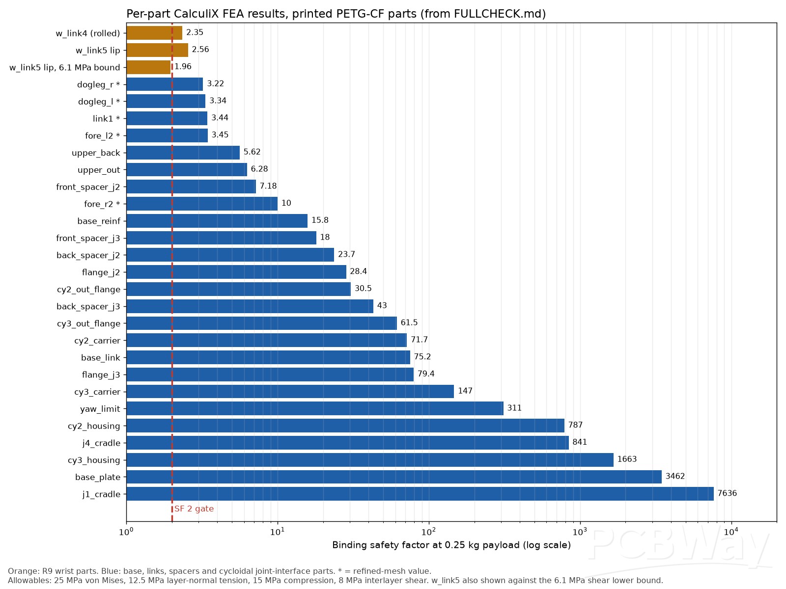
Binding safety factor per printed part at 0.25 kg payload, plotted from the FEA table in FULLCHECK.md. The red dashed line is the SF 2 target. The one bar under it is the w_link5 lip measured against the most conservative 6.1 MPa shear bound.
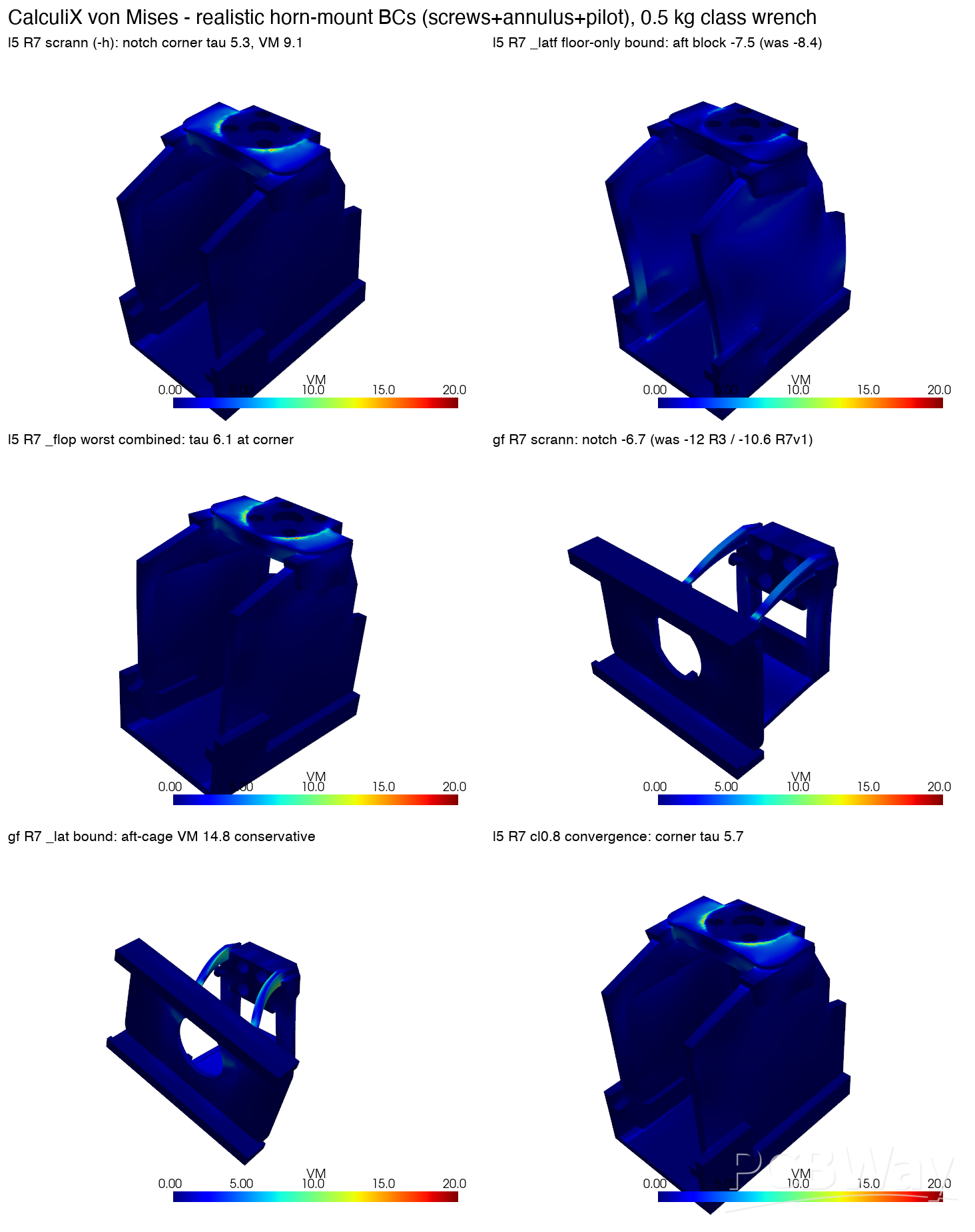
CalculiX von Mises stress plots of the wrist link and gripper frame from an earlier wrist refinement round (R7), under a 0.5 kg-class load case. The current R9 wrist was re-checked with the same method; its results are in FULLCHECK.md.
The firmware enforces the limits too. Joint torque caps (J2 3.0 N·m, J3 2.0 N·m) are clamped inside the ESCs and in the trajectory planner, and J1 is limited to ±150°, 2.5° clear of the printed stop.
Electronics and the carrier PCB
One custom board in the base, soma-carrier-v13, replaces the usual servo hub and tangle of wires. It is 135 × 115 mm, 2 layers with ground pours on both sides, and everything is hand-solderable: all through-hole apart from one SOIC-8.
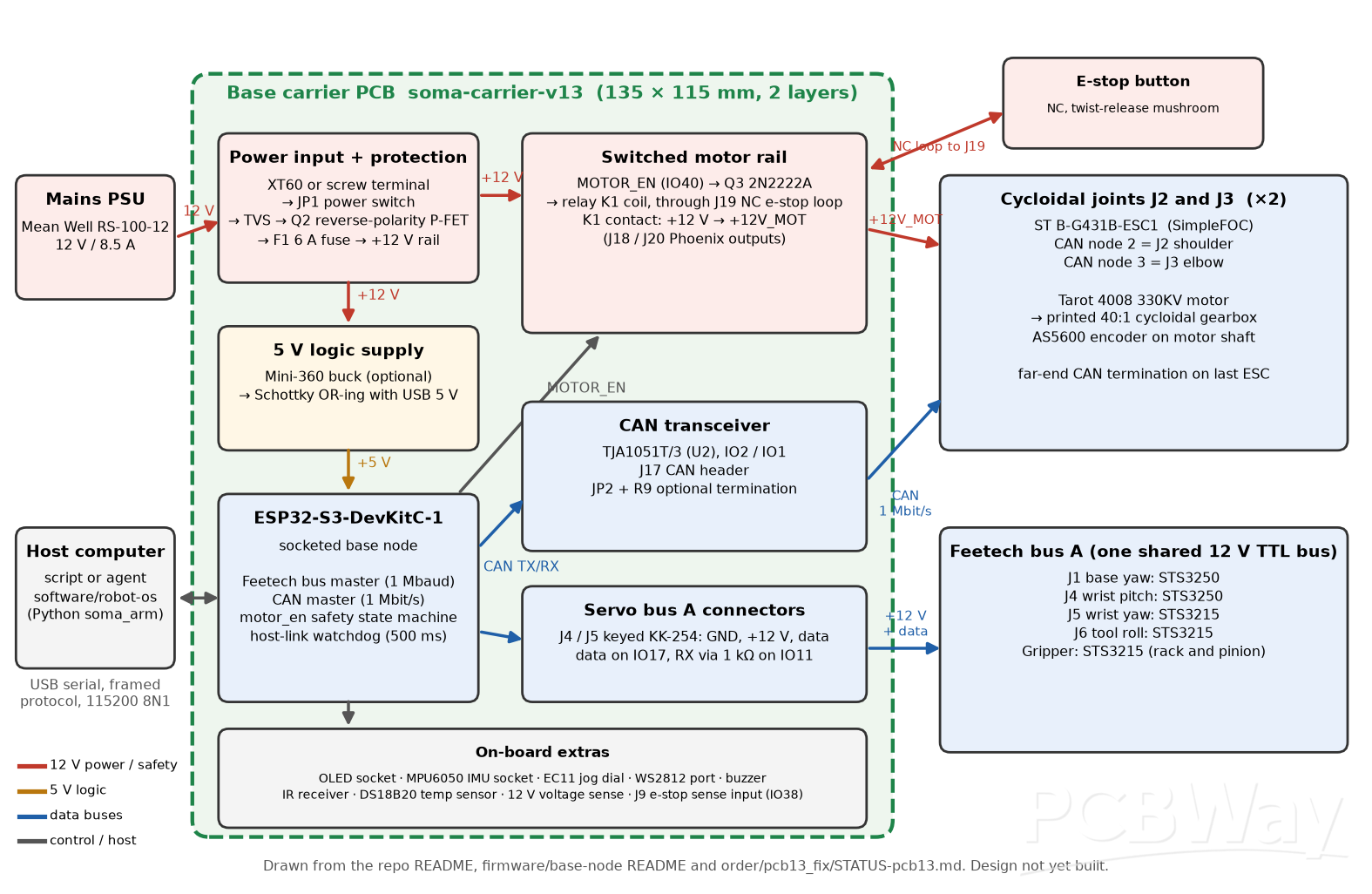
System block diagram drawn from the repo documentation: 12 V input and protection, the 5 V logic supply, the ESP32-S3 base node, the relay-switched motor rail with its hardware e-stop loop, the CAN bus to the two B-G431B-ESC1 joint drivers, and the shared Feetech servo bus.
What each block does:
- ESP32-S3-DevKitC-1 plugs into pin sockets. It is the only microcontroller in the base.
- Power input: 12 V comes in on an XT60 or a screw terminal, through a reverse-polarity P-FET and a 6 A fuse, to a +12 V rail for the five bus servos on keyed KK-254 connectors. An optional Mini-360 buck makes 5 V for the logic, with a Schottky so the devkit can stay plugged into USB.
- Switched motor rail: the MOTOR_EN pin drives a transistor and a Songle SRD-12V relay (K1), which feeds +12V_MOT to two Phoenix outputs for the J2/J3 ESCs. The relay coil runs through an NC e-stop loop (J19), so a twist-release mushroom button cuts motor power in hardware, whatever the firmware is doing.
- CAN: a TJA1051T/3 transceiver and CAN header link to the two B-G431B-ESC1 drivers at 1 Mbps.
- Extras: sockets and ports for an SSD1306 OLED, MPU6050 IMU, EC11 jog dial and WS2812 LEDs, plus a buzzer, IR receiver, DS18B20 temperature sensor, 12 V voltage sensing, status LEDs and test pads.
The board is generated by a Python script into a KiCad project. The latest DRC shows 0 electrical violations and 0 unconnected items, with only cosmetic silkscreen and library notes. A relay pad-map error was caught during review and fixed in the v1.3 files. The Gerbers are 2 layers, 1.6 mm, lead-free HASL, 1 oz copper.
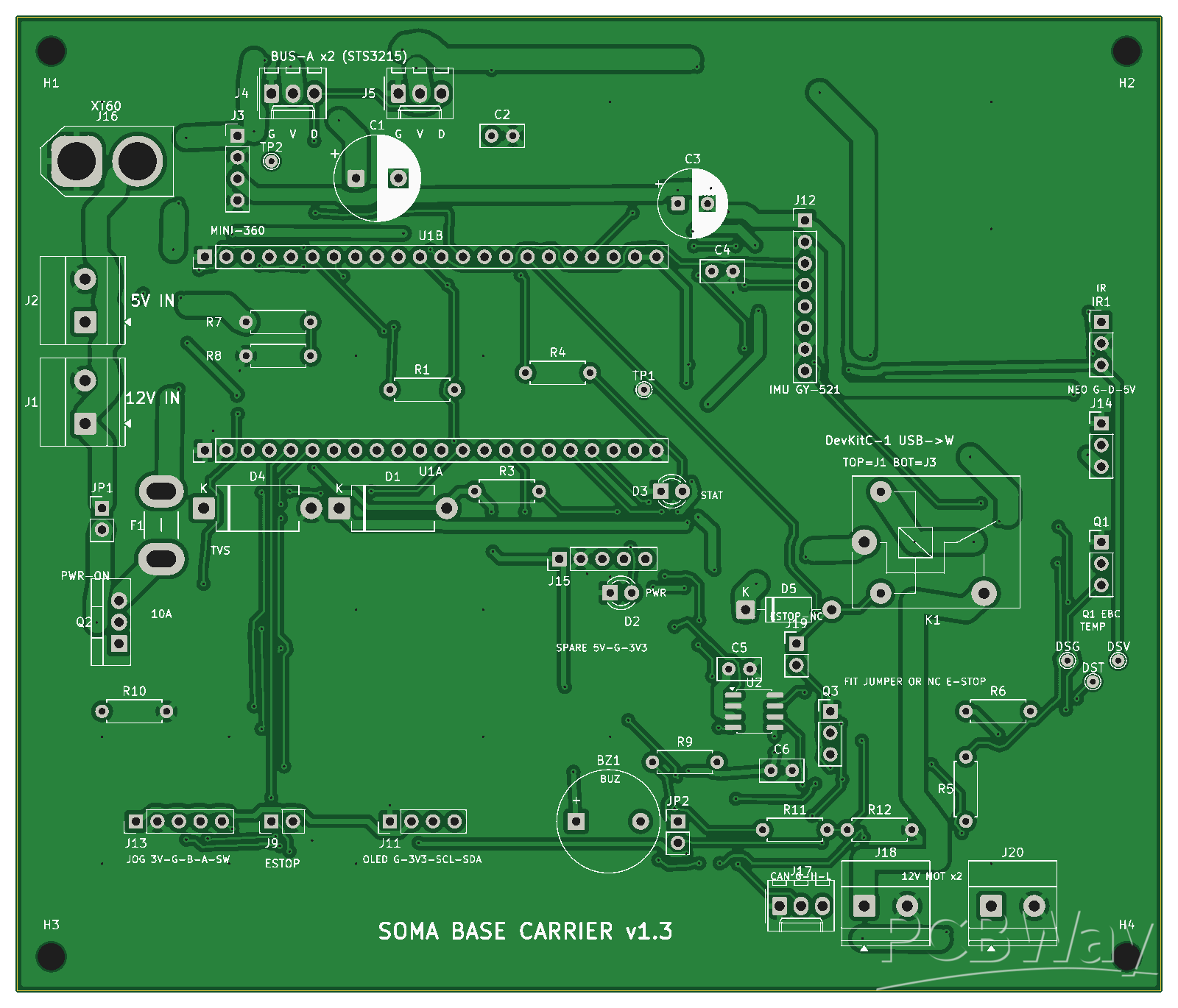
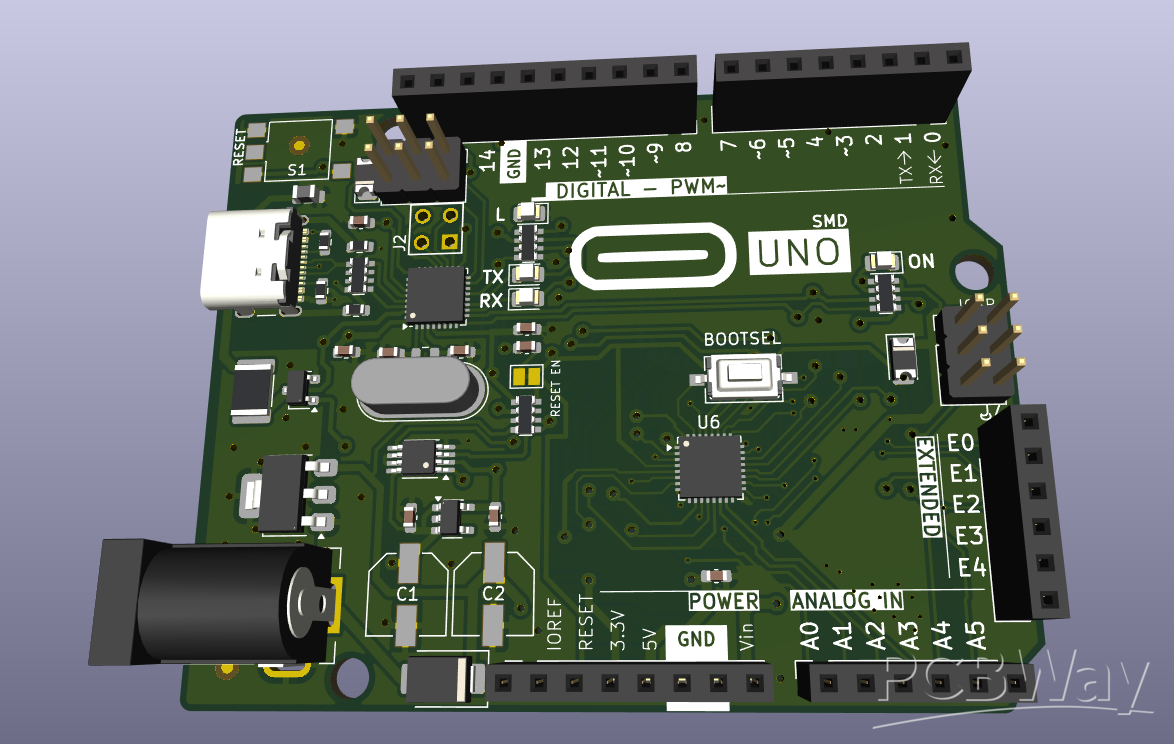
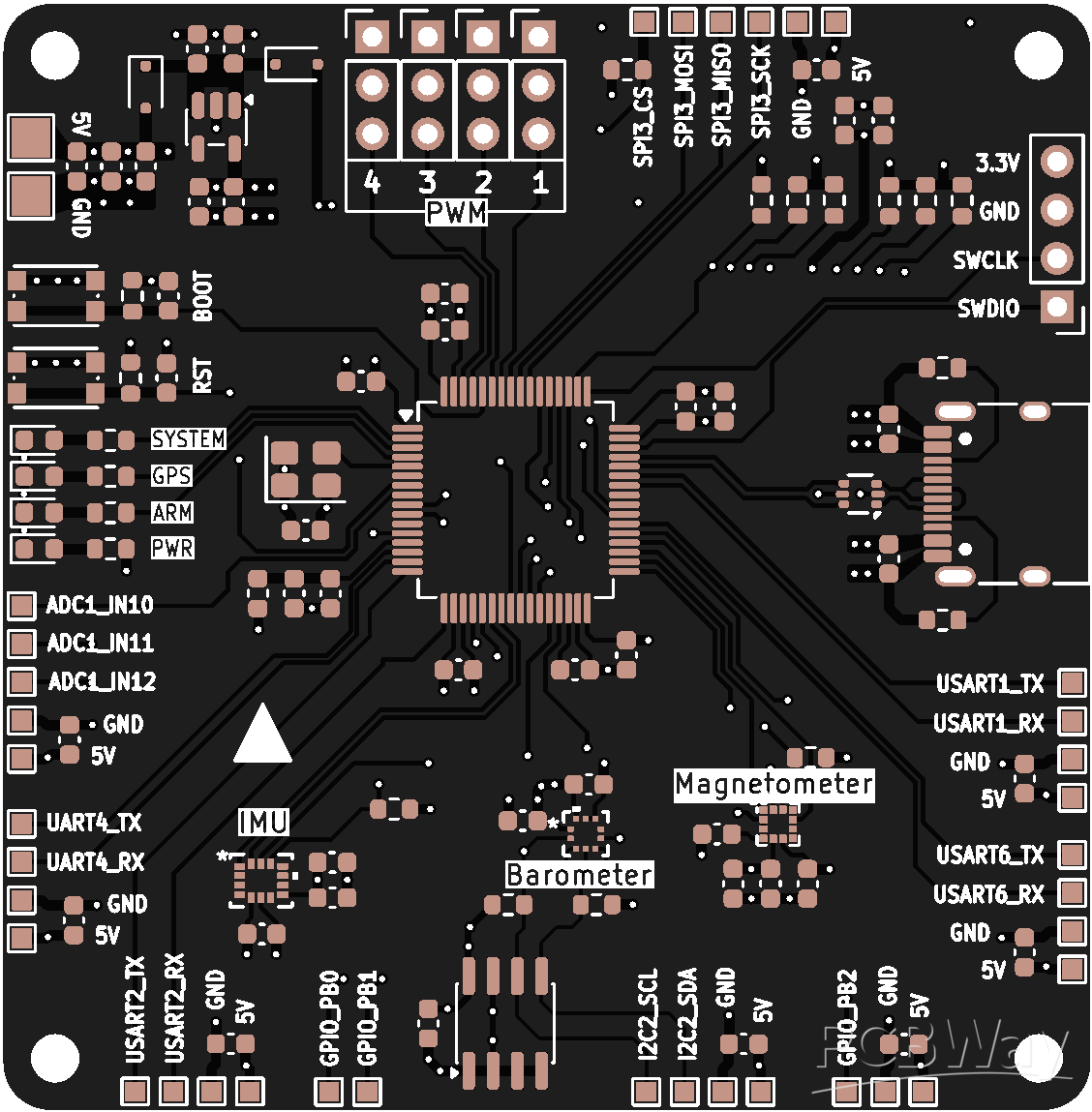
Top side of the v1.3 carrier board (copper, solder mask openings and silkscreen), rendered from the order/pcb13_fix Gerbers. The DevKit sockets are in the middle, the relay K1 and e-stop header on the right, and the 12 V input on the left.
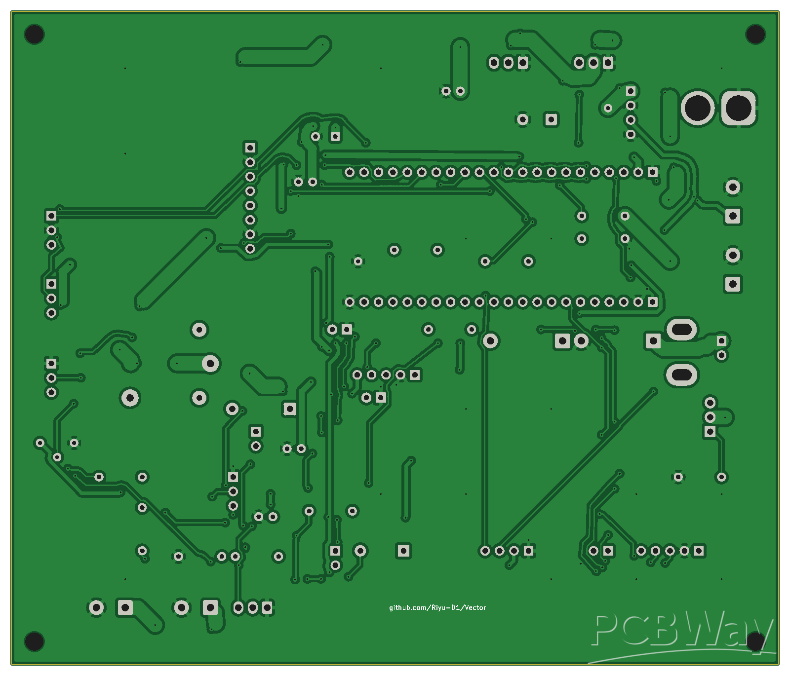
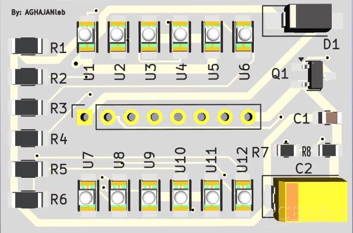
Bottom side of the v1.3 carrier board, rendered from the same Gerbers and shown mirrored as seen from below: routing and the ground pour.
Firmware and software
All of this is in the repo and builds, but none of it has run on hardware yet.
- firmware/base-node (ESP32-S3, PlatformIO): CAN master, Feetech bus master, the framed host link (115200 8N1) and a motor_en safety state machine. Motors only get power after the host explicitly arms them and every ESC checks in within a 1500 ms window. An e-stop, watchdog timeout, CAN bus-off or lost heartbeat drops the rail at once.
- firmware/joint-driver (one per B-G431B-ESC1): SimpleFOC with saved encoder calibration, hard-stop homing on every boot, phase-current clamps, a 75 ms soft-stop ramp and torque caps stored in EEPROM.
- firmware/shared: plain C codecs for the CAN, Feetech and host-link protocols.
- software/robot-os: a pure-Python soma_arm package with forward and inverse kinematics, a torque-checked trajectory planner, a gravity and payload model, a command-line tool and a simulator, so the software can be tested without any hardware attached.
Bill of materials summary
From the repo's UK parts list (GBP, November 2026). Nothing has been bought yet.
Key part | Qty | Line cost
Feetech STS3250 servo | 2 | £272.30
Feetech STS3215 servo | 3 + 1 spare | £90.24
ST B-G431B-ESC1 motor driver | 2 | £72.14
Tarot TL2955 4008 330KV motor | 2 | £69.80
ESP32-S3-DevKitC-1 | 1 + 1 spare | £33.88
Bambu PETG-CF filament, 1 kg | 1 | £32.99
Mean Well RS-100-12 PSU | 1 | £23.20
Group (all-in estimate) | Approx. £
Actuators (motors, ESCs, encoders, bearings, pins) | 244
Servos | 363
Carrier PCB, electronics, PSU, e-stop | 120
Filament, nozzle, springs, gear | 58
Fasteners, wire, adhesives, tools, gauges | 48
Totals: £674 for the checked and priced lines, or £825 all-in including estimated lines.
Build plan and what the sponsorship would enable
The next steps are printing the parts, fabricating the carrier PCB and working through the staged bring-up in docs/bringup.md:
- Print the calibration coupon and use it to check the real disc clearance before printing the four discs.
- Print the structure on the A1, fitting heat-set inserts in the J4 cradle.
- Fit the ring pins selectively and run in each cycloidal module for 200 revolutions.
- Prove the carrier board's relay and e-stop with no motors attached.
- Bring up one ESC under the live rail, then one joint on the bench, then the Feetech servos, then the assembled arm.
The carrier board is the piece that ties everything together, and it's the first thing I need to bring the arm to life safely. A sponsored batch of v1.3 boards would let me move SOMA from a verified design to a working arm on my desk. I'll document the build in the repo, including the bring-up results, and credit PCBWay.
Links
- Source, CAD, firmware, Gerbers and verification reports: github.com/Riyu-D1/Vector
- Whole-arm verification report: FULLCHECK.md in the repo
- Carrier board fabrication files: order/pcb13_fix/ in the repo
- Comments(0)
- Likes(0)