

Regeneration Braking for 6-DOF arm
Who we are:
We’re a two-person team at Texas A&M. Siddharth Rajasekaran leads product and mechanical architecture.
Angelo Reyes leads electronics and controls: motor drivers, FOC and CAN communications. We’re building a robot arm for university labs, student teams and early robotics startups, the people stuck between underpowered hobby kits and industrial arms that cost $23k–$60k (Universal Robots UR3e–UR10e). Our target is a capable arm with an estimated $1,000–$1,500 bill of materials. We get there with commodity motors, our own electronics, and proximal actuation, which keeps heavy motors near the base to cut cost and moving inertia.
How we got here:
Late 2025: control. Through Karura Robotics at Texas A&M, we started with embedded CAN control of RoboMaster motors from a Raspberry Pi Pico, then moved to STM32 firmware.
Early 2026: actuator testing. We moved to a hoverboard hub motor on a moteus controller. We characterized its resistance, inductance, KV and 30 pole pairs, tested backdrivability, and ran locked-rotor torque tests. It produced 7.44 Nm at 20 A, and its speed levelled off at 300 rpm, set by our 36 V supply rather than by the motor.
Our own driver: We also designed and built a custom DRV8313 motor driver with INA240 current sensing. Still in the works for testing and validation: https://github.com/ANGELOREYES-afk/Actuator
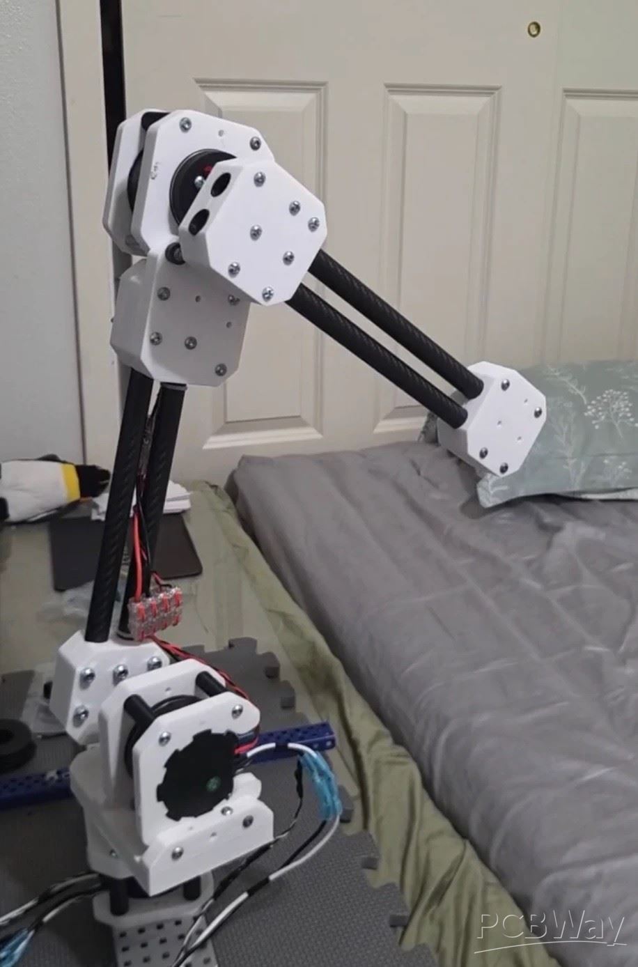
Today: a working 3-DOF arm. The arm runs on Unitree IM6014 actuators at 36 V, and we’re at the tracking stage: the joints follow commanded motion, the arm is simulated in Gazebo with inverse kinematics working, and the controls and power electronics have been modelled in Simulink and LTspice. Kinematics has been simulated and tested successfully: https://github.com/ANGELOREYES-afk/arm_3dof_sim
Next is manipulating objects in lab and home settings:
The problem this board solves. Those test numbers explain the problem. At 300 rpm the motors’ back-EMF already matches the 36 V supply. Any time a joint is pushed faster than that, by a person backdriving it, by gravity, or by hard deceleration, the motor becomes a generator and drives the bus above 36 V. A bench supply can source current but cannot sink it, so the bus voltage climbs toward the motor controllers’ 44 V limit. Each actuator also pulls around 20 A at peak torque. On top of that, plugging the supply into 4000 µF of bulk capacitance sparks the connector every time.
This board sits between the 36 V, 27 A supply and the arm’s three actuators and fixes both problems.
Brake chopper: A TL431 reference and LM393 comparator with hysteresis watch the bus. At 40.2–42.2 V (set with a trimmer) a UCC27517 gate driver switches an IRFB4110 MOSFET that dumps excess energy into a 4.7 Ω 100 W resistor. An MUR1520 diode freewheels the resistor’s inductance. It turns off about 2 V lower, so it can’t latch on at 36 V and always acts before the 44 V limit.
Precharge: A TI TPS48111-Q1 charges the bus through two 60 Ω PTC thermistors (about 1.2 A at most). Once the bus passes 60% of the supply, a comparator switches in the main CSD19536KTT MOSFET, slew-limited to about 3 A. No spark.
Reverse blocking: An LM5050-1 ideal-diode controller keeps regenerated energy out of the supply.
Protection and outputs: A 25 A / 58 V fuse, 43 V TVS diodes on the input and bus, three XT30 motor outputs, a 12 V rail, a bus-voltage ADC output and a brake-active flag.
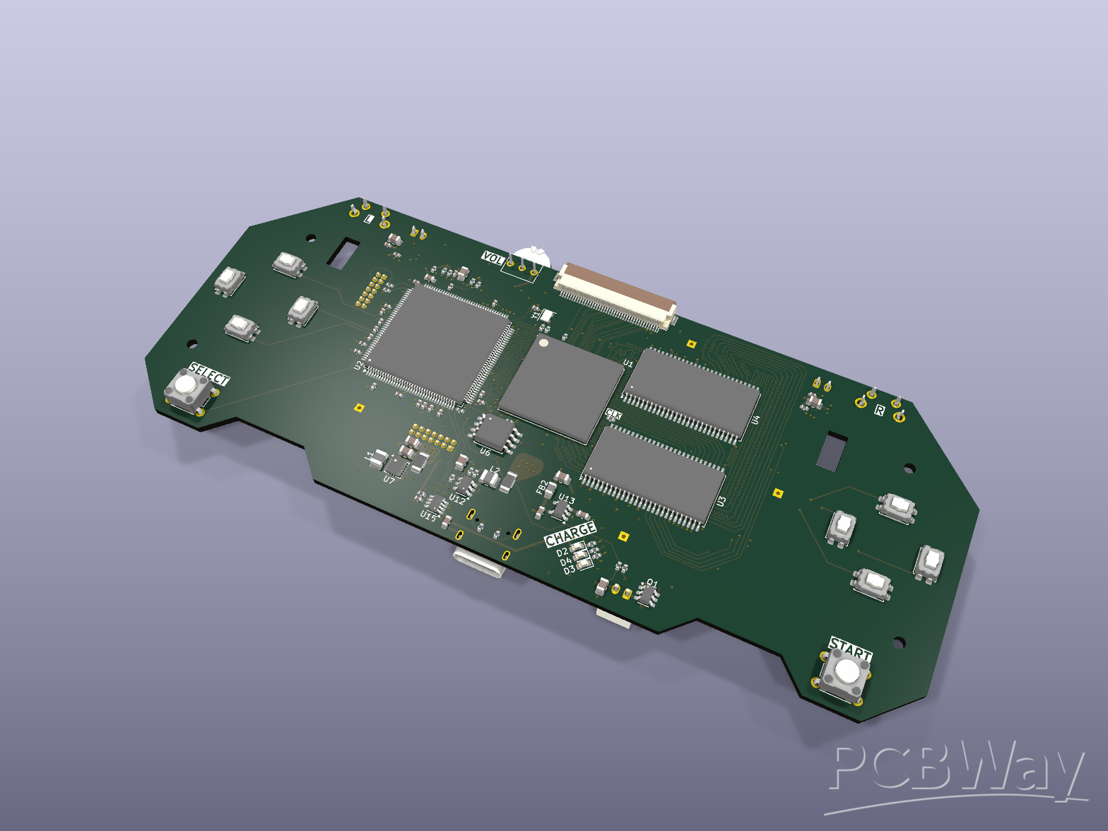
Design status: The board is at rev 3: 2 layers, 2 oz copper, 96.5 × 128 mm. Along the way we:
moved the brake window down from an early 48 V design to suit our 36 V supply
raised the fuse from 20 A to 25 A to cover the motors’ current peaks
ERC and DRC are clean, including schematic-to-layout parity. Gerbers, a BOM for full assembly (55 lines, 82 placements) and a pick-and-place file are ready. We’d like 5 assembled boards with lead-free HASL, one for each of the five beta arms we plan to build for pilot use in Texas A&M labs.
All design files are open source under CERN-OHL-S-2.0: https://github.com/ANGELOREYES-afk/vla-arm-power-board
What comes next: With the power stage under control, the next steps are an isolated RS-485 hub for the actuators and machined aluminium joint mounts. Longer term, we’re building toward our own FOC motor controller for electrically excited synchronous motors (EESMs), starting from the DRV8313 driver and current-sensing work we’ve already done. A reliable 36 V power board with a brake chopper is the foundation for all of it.
Video representation of our brake chopper:
- Comments(0)
- Likes(1)