Initial Formula KMITL
Project story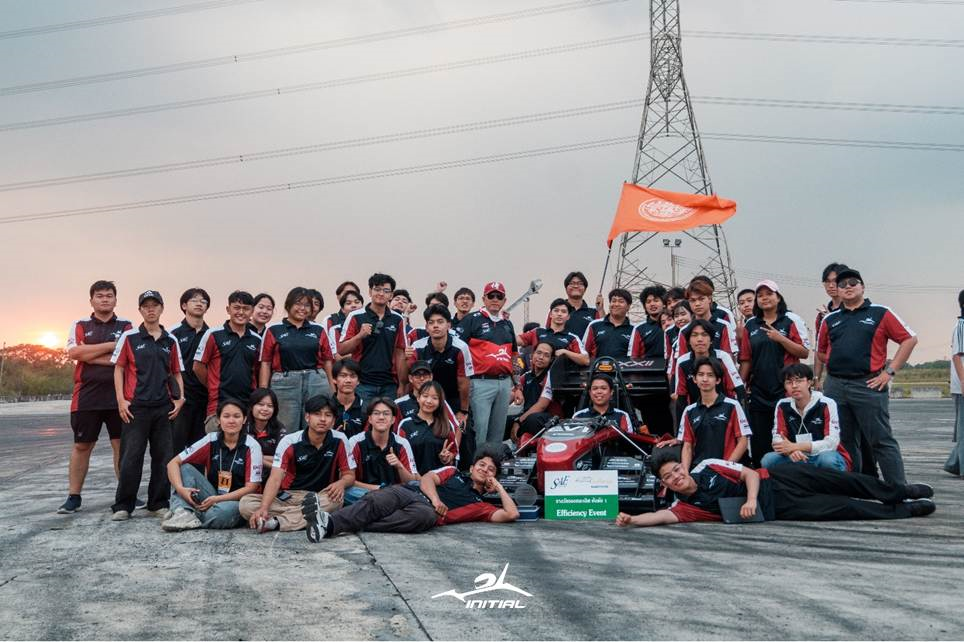
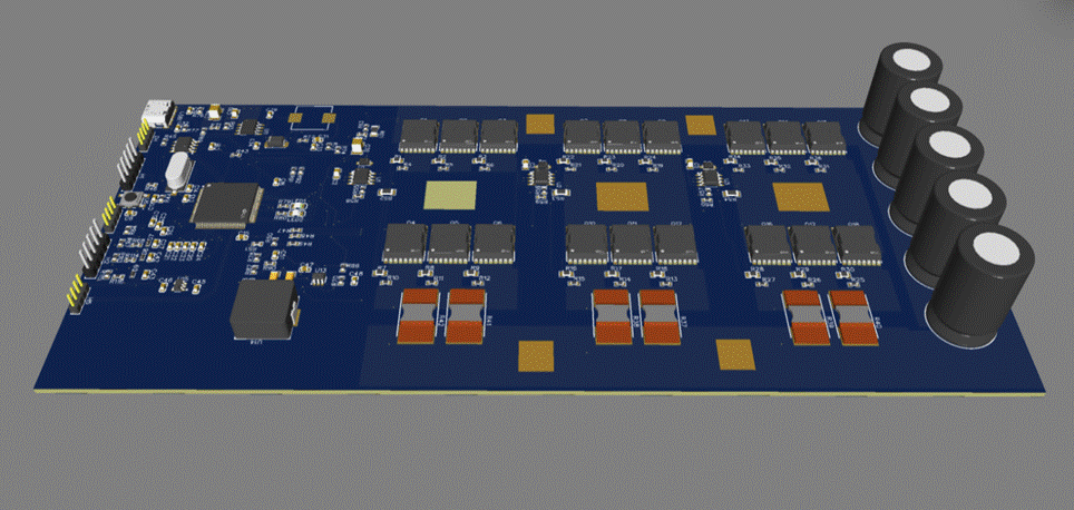
Above: our custom three-phase inverter. Eighteen MOSFETs arranged as three parallel devices per switch, six half-bridge legs, low-value shunt resistors along the bottom edge for phase current sensing, and a bank of bulk capacitors on the right - all designed in-house by students.
Built, Broken, Fixed - Usually With Very Little Time Left
If you want an honest picture of this project, start here: our boards have failed. We have lost CAN communication mid-session. We have had the car cut power. We have had the car shut down completely, on the spot, with a queue of teams waiting behind us.
Every one of those moments turned into the same scene - the electrical team with a laptop and a multimeter, the mechanical team pulling panels off and getting the car accessible, and everybody troubleshooting together against the clock. Not electrical blaming mechanical, not the other way around. One car, one problem, one team.
That is what a student-built race car actually is, and it is why we design our own electronics: when something fails, we want to be the people who can open it up, understand it, and fix it. This project is the result of that choice, and it is still being written.
Who We Are
We are Initial Formula KMITL, the Formula Student team of King Mongkut's Institute of Technology Ladkrabang (KMITL) in Bangkok, Thailand. We are students from mechanical, electrical, mechatronics, and computer engineering who share one workshop, a limited budget, and a stubborn belief that undergraduates can build a real race car.
Our team has been competing since 2005, and over the years our cars have carried names like Black Cat, Kabuto, Python, Scorpio, and Tarantula. Each one taught the next generation something. In the last few seasons we committed fully to electric powertrains, and the results followed:
• TSAE Challenge 2025 - 1st Place, EV Category, plus the Best Presentation Award
• TSAE Challenge 2026 - 2nd Place, EV Category, Winner of the Ansys Simulation Award, and Runner-up in the Efficiency Event
This November, we will represent Thailand at Formula Student Electric China (FSEC 2026) in Hefei, China. It will be our first time on this stage, competing against university teams from across Asia and beyond - many of them with budgets and facilities far larger than ours. We are going anyway.
Above: the team with our car after the TSAE Challenge, holding the Runner-up trophy for the Efficiency Event. Around forty students across mechanical, electrical, and software - together with our faculty advisors - stand behind every board in this article.
The Car
Our current car is a single-seat, four-wheel electric race car built around a high-voltage traction system and a student-assembled lithium battery pack.
• System voltage: 126 V
• Peak current: 516 A
• Motor output: approximately 60 kW
• Drive: independent motors with torque vectoring - torque is distributed between the wheels rather than fixed
• Battery: custom lithium pack, designed, assembled, and instrumented in-house
• Dynamic events: Acceleration, Skidpad, Autocross, Efficiency, Endurance
Those numbers look small next to a road car until you remember the whole thing has to be light enough to accelerate hard, safe enough to pass a strict technical inspection, and reliable enough to survive an endurance run - all while being designed and assembled by students between lectures and exams.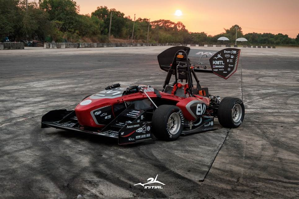
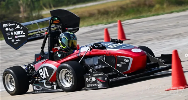
Above: our current car. Note the rear wing endplate - that is where our partners' logos live, alongside the KMITL Bangkok identity. Every sponsor who supports us is carried on this car at every event we attend, and that is exactly what we are offering PCBWay.
Why We Build the Electronics Ourselves
Buying a controller is faster. It is also, for a student team, a missed opportunity. When you buy the brain of the car, you inherit somebody else's assumptions: their switching frequency, their current limits, their fault handling, their CAN message format. When something goes wrong right before a run, you can only reboot it and hope.
When we design it ourselves, four things change:
• We can debug at the source. A scope probe on our own gate drive tells us exactly what is happening - no guessing, no support ticket.
• We can tune for our car. Our motor, our pack, our gearing, our events. Nothing is a compromise made for a different application.
• We can defend our design. In Formula Student, engineering design is scored. Judges ask why - and we can answer with our own calculations, simulations, and test data.
• Our members actually learn. A student who has laid out a 500 A power stage, blown it up, and fixed it has a skill no lecture can hand out.
That last point is really the whole reason our team exists.
The Hard Parts: Failures, Field Fixes, and Teamwork
We would love to say the boards worked first time. They did not. Here is what actually happens when students build the electronics for a high-voltage race car.
Boards fail, and they fail at the worst possible moment
We have damaged boards during development and during testing. A race car is an electrically hostile environment: high current, fast switching, vibration, heat, and connectors that get plugged and unplugged far more often than in any consumer product. Every failure cost us time we did not have - and taught us something we could not have learned from a datasheet.
Losing CAN
One of the most frustrating failures we have chased is losing CAN communication. When the bus drops, the dashboard stops updating and the car loses the link between its systems. Debugging that means checking wiring and connectors, termination, grounding, and noise coupling - often while the car is already out and the session clock is running. It is also a large part of why our dashboard now uses a fully isolated CAN interface: we designed the fix into the hardware.
The car cutting power, and the car shutting down
We have had the car cut torque, and we have had it shut down completely. In a Formula Student EV that is often the safety system doing exactly what it is supposed to do - but knowing that does not tell you which sensor, which signal, or which connection triggered it. Tracing a shutdown back to its root cause, under time pressure, with the car half-disassembled, is one of the most demanding things our team does.
Fixing it as one team
The part we are proudest of is not any single board - it is how the team responds when something breaks. Our electrical and mechanical members work the problem together: mechanical gets the car open and the hardware accessible, electrical probes, measures, and reasons through the fault, and both sides argue their way to the actual cause instead of the convenient one. We have done this in the paddock and in the workshop, more than once with people waiting on us.
Solving problems on the spot, as a team, under pressure, is a skill no course teaches - and it is a large part of why our members come back season after season.
Money and iteration
Every prototype revision is real money that our team has to raise ourselves. There have been revisions we knew we should make and could not afford to make, so we patched, worked around them, and carried on. Nothing slows an engineering team down like being unable to press "order" on the next version of a board.
1. Custom 3-Phase ESC - 72 V / 10 kW Motor Controller
Above: the complete schematic for the inverter - MCU and sensing on the left, the three half-bridge legs with their gate drivers and current-sense amplifiers on the right, and the multi-stage power supply chain along the bottom. Drawn from scratch by our students.
This is the most ambitious board we have ever built: a complete three-phase inverter and motor controller, designed from a blank schematic by our students.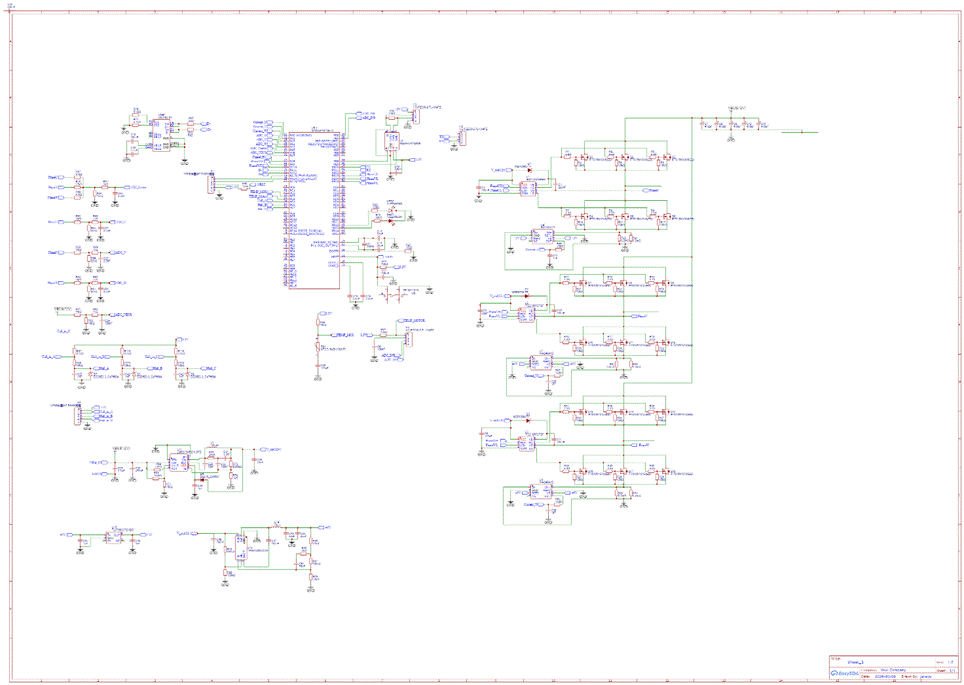
Power stage
• 18x IPT015N10N5 MOSFETs - three devices in parallel per switch, six switches in total, so current is shared and conduction losses drop
• IRS21867S high-side / low-side gate drivers, one per phase leg
• Individual gate resistors per device, so paralleled MOSFETs turn on together instead of fighting each other
• Bulk capacitor bank of 5x 470 uF placed close to the switching devices to keep the commutation loop tight
• Wide copper pours and multiple thermal pads to spread heat out of the power stage
Sensing and control
• STM32F407VET6 running the motor control loop
• INA240A1D current-sense amplifiers with 0.2 mOhm shunts on each phase - chosen specifically for their enhanced PWM rejection, which is what finally gave us clean current measurement in a hard-switching inverter
• Phase voltage sensing on U, V, W and the center point, for observer-based and sensorless control work
• Hall sensor inputs with ESDA23-3 ESD protection - rotor position signals come from outside the box, so they get protected
• DC bus voltage sensing on the 72 V rail
• Two NTC temperature sensors - one watching the MOSFET bank, one watching the motor
Power supply chain
• LM5017 wide-input buck converter: 72 V down to 12 V
• TPS54308: 12 V down to 5 V
• TLV75633: 5 V down to 3.3 V
• SN65HVD230 CAN transceiver so the controller talks to the rest of the car
• USB and SWD header for programming and live debugging
Firmware
Our control firmware is based on the open-source VESC project, adapted to our own hardware. This was a deliberate engineering decision, not a shortcut: by standing on a proven, well-tested FOC implementation, we could put our effort into validating our own power stage, sensing, and thermal design first - the parts where a mistake destroys hardware. It is the first step of a longer roadmap, and we are already working on what replaces it.
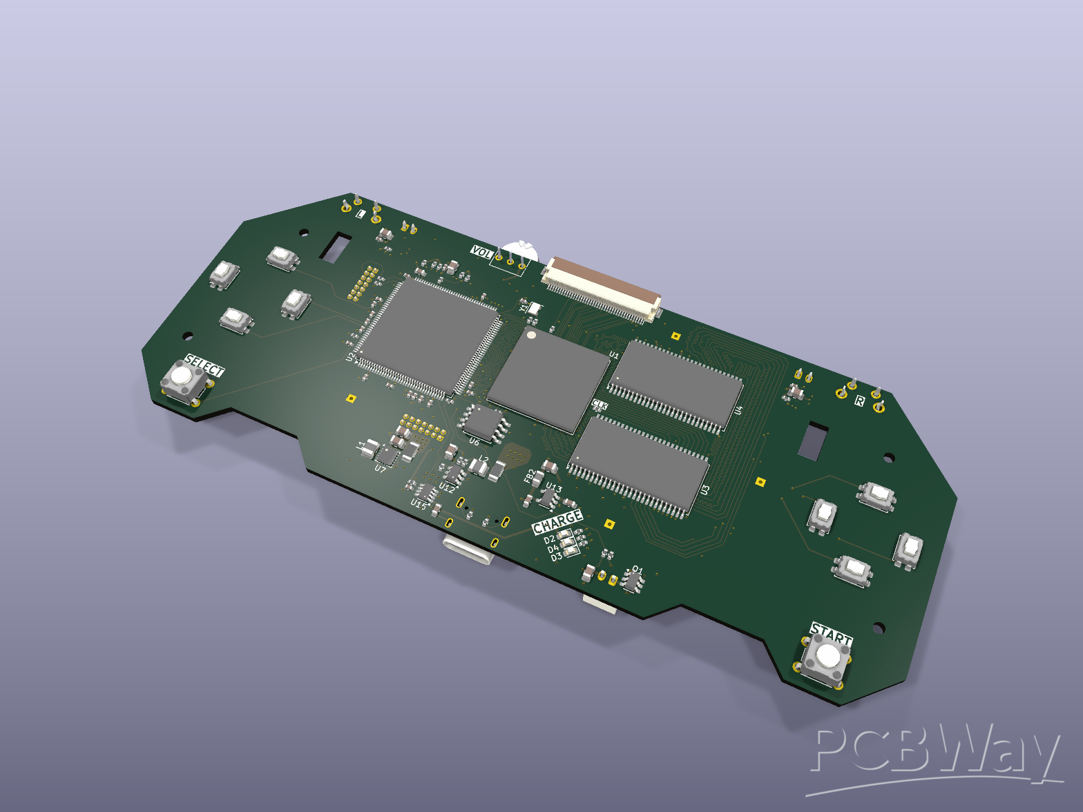
2. "Dach" - Isolated CAN Dashboard with Its Own Battery
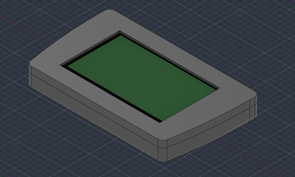
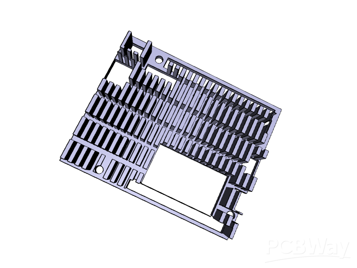
Above: the dashboard enclosure, designed in CAD around the display and our board. Rounded corners, a recessed bezel that protects the screen edge, and a serviceable two-part shell - because during a race weekend, being able to open something quickly matters.
A driver in a race car has a fraction of a second to read information. A dashboard that is slow, unclear, or unreliable is worse than none at all - and in an EV, it must never become a path for a fault to travel. So we designed our own.
How it works
The dashboard is a display module that receives live vehicle data over the CAN bus and renders it for the driver: pack voltage and current, temperatures, motor and controller state, speed, and any active faults or warnings. The controller broadcasts, the dashboard listens and draws.
Key design decisions
• ESP32-S3-WROOM-1 as the main controller, driving a Nextion intelligent display over UART - the display handles rendering, the ESP32 handles the data
• Fully isolated CAN interface - an ISO1044 isolated transceiver plus an isolated DC-DC converter puts a galvanic barrier between the vehicle bus and the driver-facing electronics. On a car with a high-voltage traction system, that barrier protects the network from ground loops and stops a fault on one side from propagating to the other.
• Its own battery - a TP4056 lithium charger with DW01A and FS8205A protection, plus an MT3608 boost converter, gives the dashboard an independent power source. That means we can power up the display for diagnostics, configuration, and pit-lane checks without energizing the car's high-voltage system at all. It is safer for the team and far faster to work with.
• USB-C for charging and programming
• CDSOT23-SM712 TVS protection on the CAN lines, because a race car is an electrically hostile place
We designed the interface too, not just the board
The screen the driver sees is our own design as well. We drew the dashboard interface ourselves - the layout, the digits, the battery and status indicators, the bar graphs, and the on/off states - around a top-down view of the car, so that critical information is where the driver expects it and readable in a fraction of a second. Choosing what NOT to display turned out to be just as important as choosing what to show.
Designed to actually live in a race car
The electronics are only half of it. We also designed the enclosure in CAD so the display sits at a readable angle in the cockpit, the board and screen are protected from vibration and debris, and the whole assembly can be mounted and removed quickly during a session. A dashboard that cannot survive the car is not a dashboard.
It is a small board, but it is the part of the car the driver actually looks at - and the part that tells the pit crew whether something is going wrong before it becomes expensive.
3. The Safety Systems - The Boards That Decide Whether We Race
In Formula Student EV, no amount of performance matters if the car cannot pass technical inspection. A large part of that inspection is the safety electronics, and the rules are specific about what must exist and how it must behave. We designed those boards ourselves too.
Shutdown Circuit board
This is the board that can stop the car. It gathers the three mandatory safety inputs - the Insulation Monitoring Device (IMD), the Battery Management System (BMS), and the Brake System Plausibility Device (BSPD) - and combines them in hardware logic. If any one of them signals a fault, the shutdown circuit opens and the high-voltage system is disconnected. It is built around discrete CMOS logic and automotive relays with a latching behaviour and a manual reset, so a fault cannot simply clear itself and let the car re-energize on its own.
• Hardware logic (CD4077-based) combining IMD, BMS and BSPD states - no microcontroller in the critical path
• Automotive relays for each safety branch, driven by logic-level MOSFETs
• Dedicated test switches for IMD, BMS, and BSPD so the fault path can be demonstrated to a scrutineer on demand
• Latching fault behaviour with an explicit reset, plus status indicators for each branch
BSPD - Brake System Plausibility Device
The BSPD exists to catch one specific dangerous condition: the car drawing significant power while the brakes are firmly applied. Our board reads a current signal from a Hall sensor and a brake pressure sensor, compares each against a threshold with op-amp comparators, and ANDs the two conditions in hardware. If both are true for long enough, it drives a relay that opens the shutdown circuit.
• LM258-based analog comparators with adjustable thresholds (trimmers) for both brake pressure and current
• 74HC08 AND logic - the fault only triggers when both conditions are genuinely present
• Relay output tied directly into the shutdown circuit, and a status LED for inspection
• Entirely analog and logic based - no firmware to argue about during scrutineering
APPS board - the pedal, done to the rules
The Accelerator Pedal Position Sensor board turns the driver's foot into a verified torque request. The rules demand redundancy: two independent pedal sensors must agree with each other, and torque must be cut if they disagree or if the pedal and the brake are pressed together. Our upgraded design reads both throttle channels and the brake signal through dedicated 16-bit ADCs, runs the plausibility checks, and publishes the result onto the vehicle CAN bus.
• Two independent throttle inputs plus a brake input, on screw terminals for a robust in-car connection
• ADS1115 16-bit ADCs for clean, high-resolution pedal measurement rather than relying on a noisy on-chip ADC
• ESP32-WROOM controller running the plausibility logic
• MCP2515 CAN controller so the pedal request goes onto the same bus as everything else
These three boards are unglamorous. They will never win a lap time. But they are the difference between rolling onto the track and being sent back to the paddock - and designing them ourselves means we can explain and demonstrate exactly how each one behaves when a scrutineer asks.
4. The Rest of the System
• Power Gate board - high-current switching and power distribution with paralleled MOSFETs
• GPS module - position and speed logging for lap and track analysis
• Data-logging board (in development) - so every test session produces data instead of opinions
• Main control board (in development) - the central vehicle controller, and our next big step
5. We Do Not Just Build Boards - We Model Them First
Hardware this expensive cannot be designed by intuition alone. Alongside the electronics, our team runs a full modelling, simulation, and validation program - and it is what turns a set of boards into an engineered system.
Vehicle and powertrain modelling
We build our vehicle dynamics and powertrain models in MATLAB / Simulink: acceleration and lap simulation, powertrain and energy modelling, control design, suspension geometry, and tyre behaviour. Before a control strategy ever runs on the car, it runs in the model.
State estimation and control research
• Extended Kalman Filter (EKF) work for both vehicle state estimation and thermal state estimation
• Torque vectoring and control allocation studies, including ablation tests to see what each part of the controller actually contributes
• Neural-network based compensation experiments layered on top of the baseline controller
• Bayesian optimization used to tune parameters instead of guessing
Thermal and cooling design
Our inverter's thermal path is designed, not hoped for. We model inverter losses (conduction and switching separately), design a liquid cold plate, and verify it with CFD and FEA before anything is machined. Cooling is not an afterthought bolted on at the end - it is part of the electrical design.
And then we check it against the real car
This is the part we care about most: our models are validated against logged data from the actual car. We record real test sessions from the controller - motor and input current, input power, estimated inverter losses, and measured MOSFET and motor temperatures - and compare them against the simulation. Peaks above 200 A of motor current, the thermal rise during hard running, and the way the system settles afterwards are all data we can point at, not numbers we assumed.
That workflow - model, build, test, log, compare, correct - is why we won the Ansys Simulation Award at TSAE Challenge 2026, and we are preparing a submission for the MATLAB / Simulink Modelling and Simulation Award at the Formula Student China series this season as well.
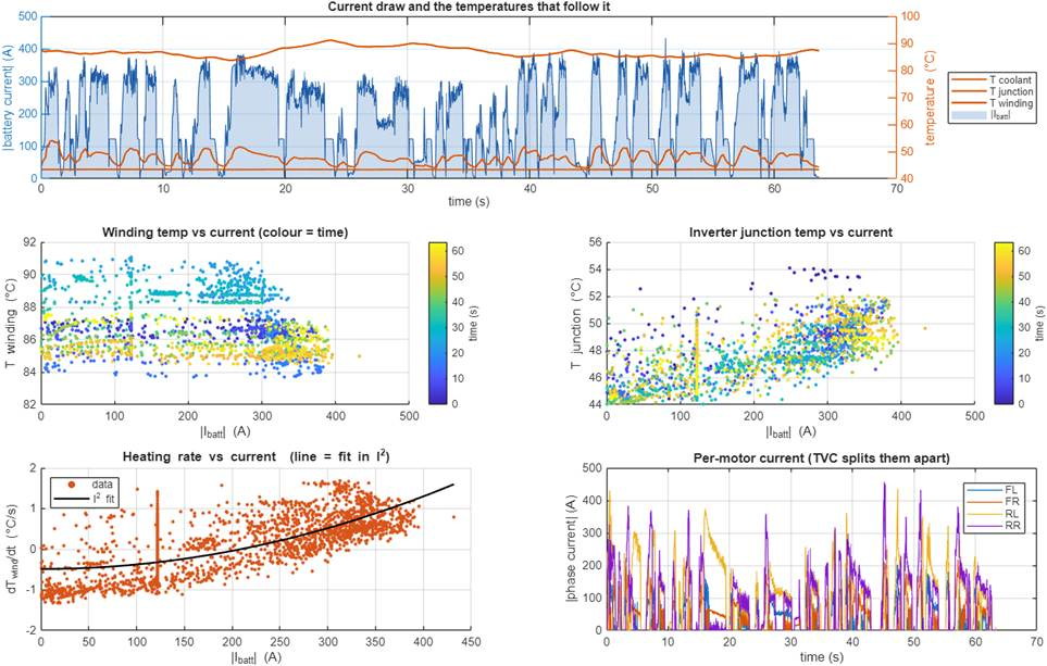
Above: the kind of analysis this workflow produces. Top: battery current demand through a run, with coolant, inverter junction, and motor winding temperatures tracked alongside it. Middle: winding and junction temperature against current, coloured by time, so we see thermal behaviour evolve rather than just its peak. Bottom left: heating rate against current, fitted to an I-squared law - the physics we designed to, confirmed by data. Bottom right: per-motor phase current, where the four traces separate visibly as torque vectoring distributes torque between the wheels.
The Road to Hefei
Qualifying to compete internationally is one problem. Actually getting there is another one entirely.
Between now and November we have to finish and validate the remaining boards, keep testing a car that is still being developed, and then physically move a race car, tools, spare parts, and a student team from Bangkok to Hefei. For a team funded by sponsorship and student effort, the logistics are as challenging as the engineering.
We are doing it because a group of undergraduates from Thailand building a competitive electric race car - and taking it to an international competition - is worth doing.
Where We Are Going Next
This project is not finished, and that is deliberate. What we have built is the first generation of a system we intend to keep developing:
• Firmware: we started on VESC-based control to get a reliable foundation. We are now researching our own control strategy, so that eventually both the hardware and the software running on it are ours end to end.
• Hardware: the next-generation main control board and integrated data logging are in active development, with the goal of one tightly integrated vehicle control system rather than several separate boards.
• Process: better simulation before fabrication (our Ansys award came from taking that seriously), better test procedures, and better documentation so the next generation of students does not start from zero.
Every board we make is designed, built, broken, understood, and re-designed by students. That loop is the actual product of this team - the cars are just the evidence.
How PCBWay Support Would Help Us
For us, PCB quality is not a nice-to-have. A weak board in the safety chain is the difference between passing technical inspection and watching the competition from behind a fence. And every prototype we cannot afford is a design lesson we do not get to learn.
Support from PCBWay for PCB fabrication - and PCBA / assembly where possible - would directly let us:
• Manufacture safety-critical boards to a standard we can trust at full power
• Iterate properly during development instead of rationing prototype revisions
• Finish the data-logging and main control boards in time for FSEC 2026
• Keep the next-generation controller research moving after this season ends
We can provide Gerber files, board specifications, stack-up requirements, and quantities as soon as the scope is confirmed - several designs are already exported and ready to order.
How We Will Showcase PCBWay
• PCBWay logo on our race car, battery pack, and team apparel at an international competition
• Dedicated posts featuring PCBWay across our channels (Instagram / Facebook: Initial Formula KMITL) through the build, testing, and the competition in China
• Photos and video from the build and from FSEC 2026 in Hefei, which PCBWay is welcome to use on its own channels
• Continued project updates here on the PCBWay community, including our next-generation controller development
• We already carry our partners' logos on our hardware and our car - we deliver on our sponsorship commitments
Words to PCBWay
Thank you for supporting student engineering teams around the world. We are a group of Thai students who decided to build the most important parts of our car ourselves - the inverter, the dashboard, the sensor interfaces - and to keep rebuilding them every time something failed.
Your support would help us finish what we started and carry it to Hefei this November, representing Thailand at Formula Student Electric China 2026. We would be genuinely proud to have PCBWay on our car.
Apply for sponsorship >>- Comments(0)
- Likes(1)