Esp32 based MP3 player
I'm Yash, a B.Tech ECE student and hardware hobbyist who loves building things from the ground up — from FPGA-based systems to full audio PCBs like this one for fun.
In an era of smartphone distractions and streaming subscriptions, I wanted a music player so instead of buying one I build one on prototype board and solder it on my own.
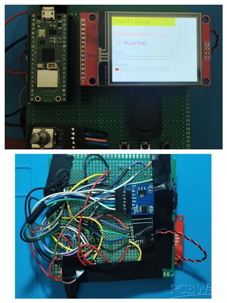
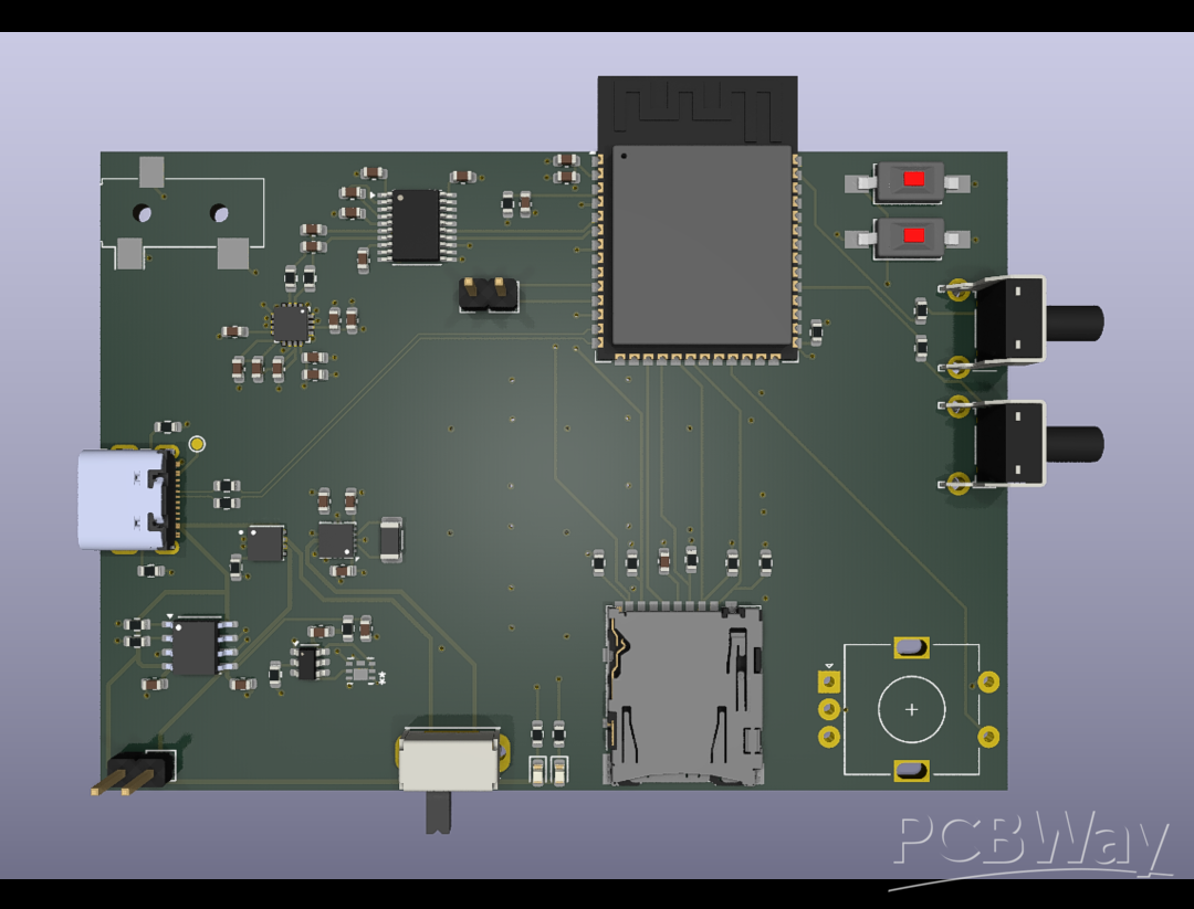
And now designed custom-engineered ESP32-S3 MP3 player that combines retro aesthetics with modern, production-grade hardware architecture. It is designed not just to play music, but to serve as a masterclass in mixed-signal 4-layer PCB design, efficient power management, and clean audio routing.
Hardware & Features
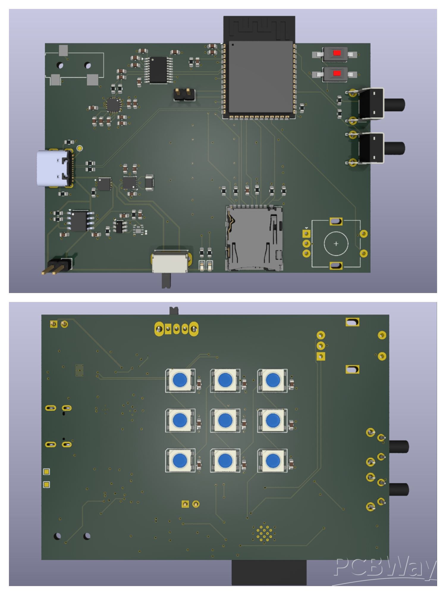
Core Processing: Powered by the robust ESP32-S3, providing plenty of processing overhead for handling audio streams.
High-Speed Storage: The MicroSD card is wired in native 4-bit SDMMC mode. Skipping standard 1-bit SPI allows for drastically higher read speeds, which is essential for smoothly loading and playing high-bitrate or lossless audio files.
Hi-Fi Audio Pipeline: The ESP32 outputs digital audio via I2S to a dedicated PCM DAC, which feeds into a TPA audio amplifier. This analog signal is then routed to a 3.5mm audio jack, delivering a significantly cleaner and richer sound profile than standard microcontroller PWM audio.
Interactive UI: Navigation and volume control are handled by a tactile rotary encoder, while visual feedback is provided by a sleek 3x3 grid of WS2812B addressable LEDs mounted on the rear of the board.
Advanced Power Management
Power delivery was one of the biggest challenges I wanted to tackle with this design.
Auto Power MUX: I implemented a dedicated Power MUX IC that automatically and seamlessly switches between USB-C power and battery power without interrupting the music.
Battery Protection & Charging: The board features a TP4056 charging IC paired with a dual N-channel MOSFET IC and DW10A to provide strict over-charge, over-discharge, and short-circuit protection for the LiPo battery.
High-Efficiency Buck Converter: Instead of relying on standard LDOs, which would overheat under the load of the ESP32, the audio amplifier, and 9 addressable LEDs, I used a buck converter to efficiently step down the voltage while keeping thermals perfectly in check.
4-Layer PCB Design & Routing
To make all these complex subsystems play nicely together without EMI or noise issues, I stepped up to a 4-layer stackup.
I carefully partitioned the layout to ensure maximum audio clarity. The noisy components—like the power MUX, battery management system (BMS), and high-frequency switching buck converter—are strictly isolated in the bottom-left quadrant. Meanwhile, the sensitive analog audio circuitry (the PCM DAC and TPA amp) sits completely separated in the top-left quadrant.
Sponsorship from PCBWay would let me keep building and sharing projects like this one with the community.
Apply for sponsorship >>- Comments(0)
- Likes(1)