D.R.E.A.M.S
D.R.E.A.M.S: an autonomous boat that maps water quality
It drives itself across ponds and lakes, samples the water as it goes, and maps what it finds.
D.R.E.A.M.S (Data Recovery for Environmental And Marine Surveillance) is an autonomous boat that maps water quality in ponds, lakes and other small bodies of water. You give it a route on a map, and it drives itself from point to point, sampling the water and sending the readings back to shore. I'm building it with Matthew Hong, Nolan Ting and Caleb Kong, all Mechanical Engineering students at Northeastern University.
Why we're building it
It started as a first-year project in London. Reading about how something works has never been enough for me; I have to build one, and Matthew and I wanted to see a boat of ours actually work on real water. Since then, talking with the Charles River Watershed Association and the Port of Oakland showed us how much water sampling is still done by hand, down to sending divers for sediment samples. That's what keeps us building.
What it does
V3 is built around three jobs:
It drives itself. Draw a route and sampling stations in the web dashboard, and the boat steers itself between them using GPS and a compass. A hand-held RC transmitter can take over at any time.
It samples the water. At each station, a sensor pod on a tether reads pH, dissolved oxygen, conductivity (TDS), turbidity and temperature.
It maps the results. A fish-finder sonar measures the depth, and every reading is tagged with its GPS position and shows up on a live map over 4G.
The pictures below show D.R.E.A.M.S at a glance.
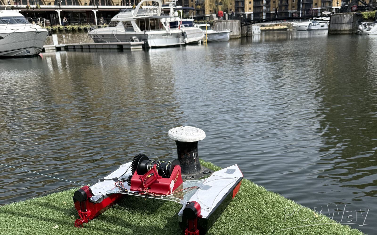
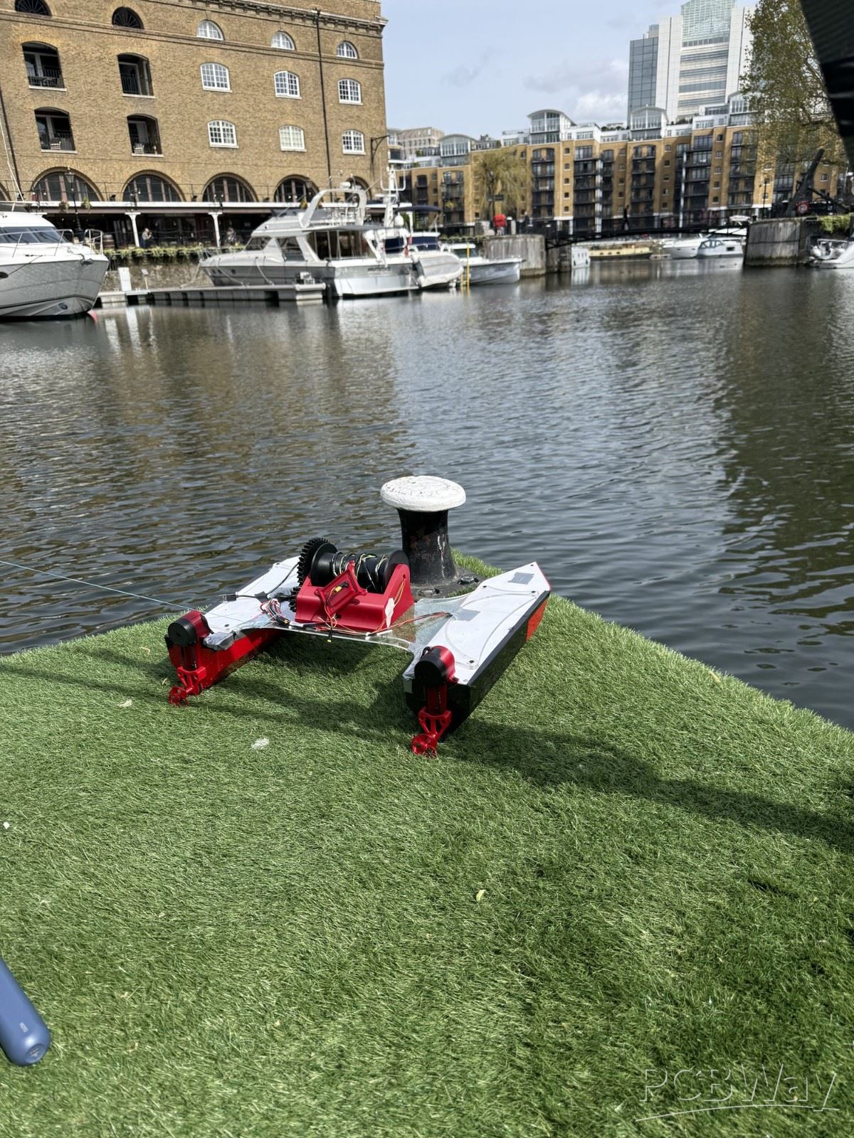
V1 at St Katharine Docks, London, where it drove itself to GPS waypoints.
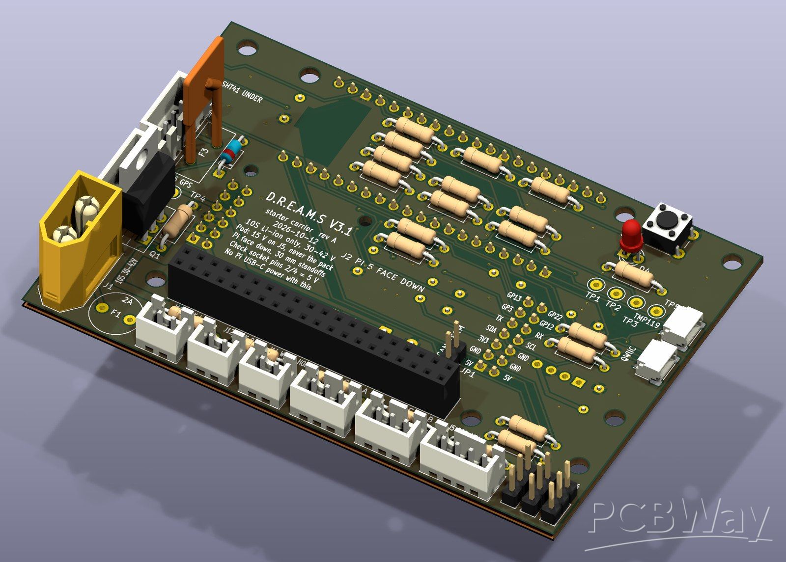
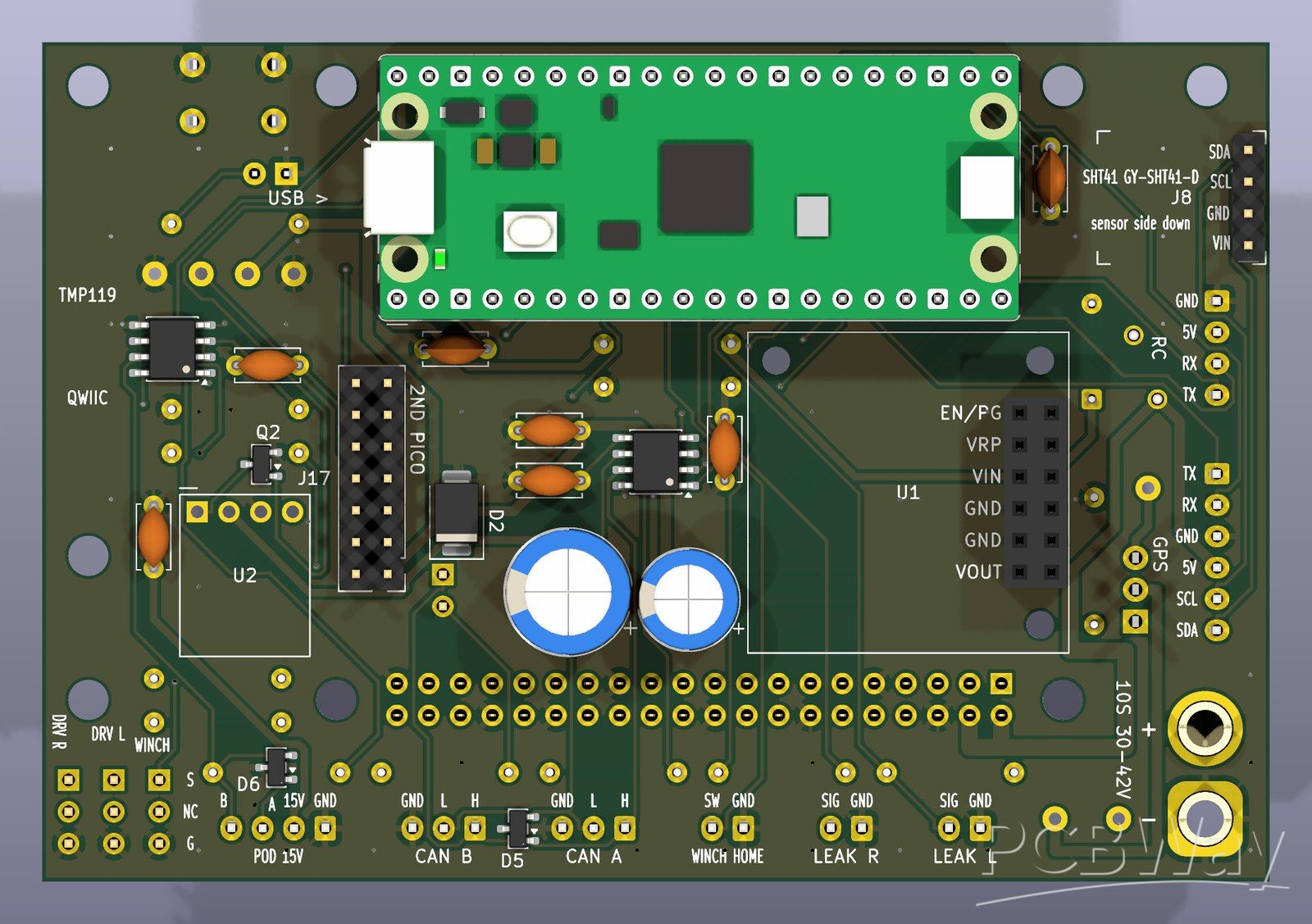
The V3.1 starter carrier board.
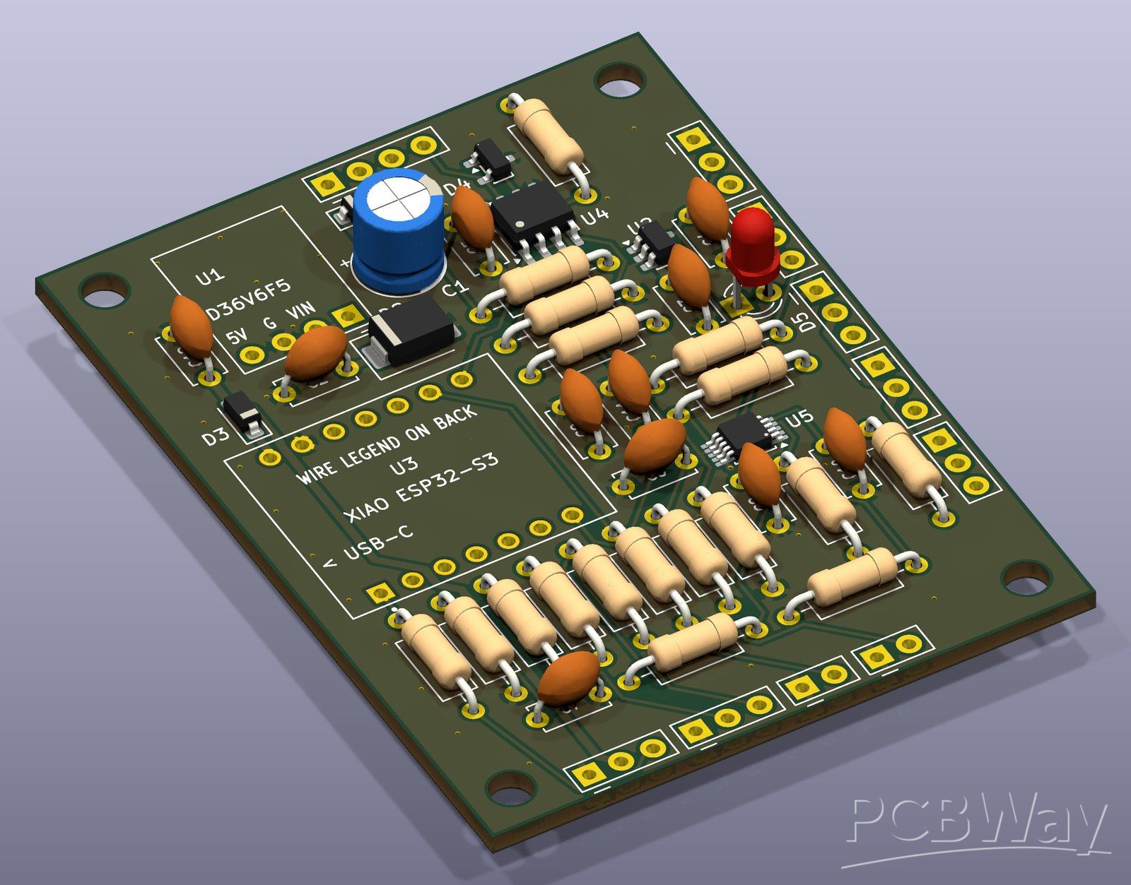
The sensor-pod board.
How we got here
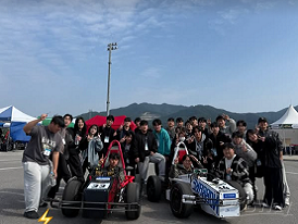
V1 (spring 2026) was built in one semester in London. We weren't expected to do all of this in one semester, but we went way overboard: 3D-printed hulls sealed in marine epoxy, a winch that lowered a sensor pod to the bottom, and a radio link of about 1 km. It drove itself to GPS waypoints at St Katharine Docks and ended up at the Creators' Showcase at Northeastern University London.
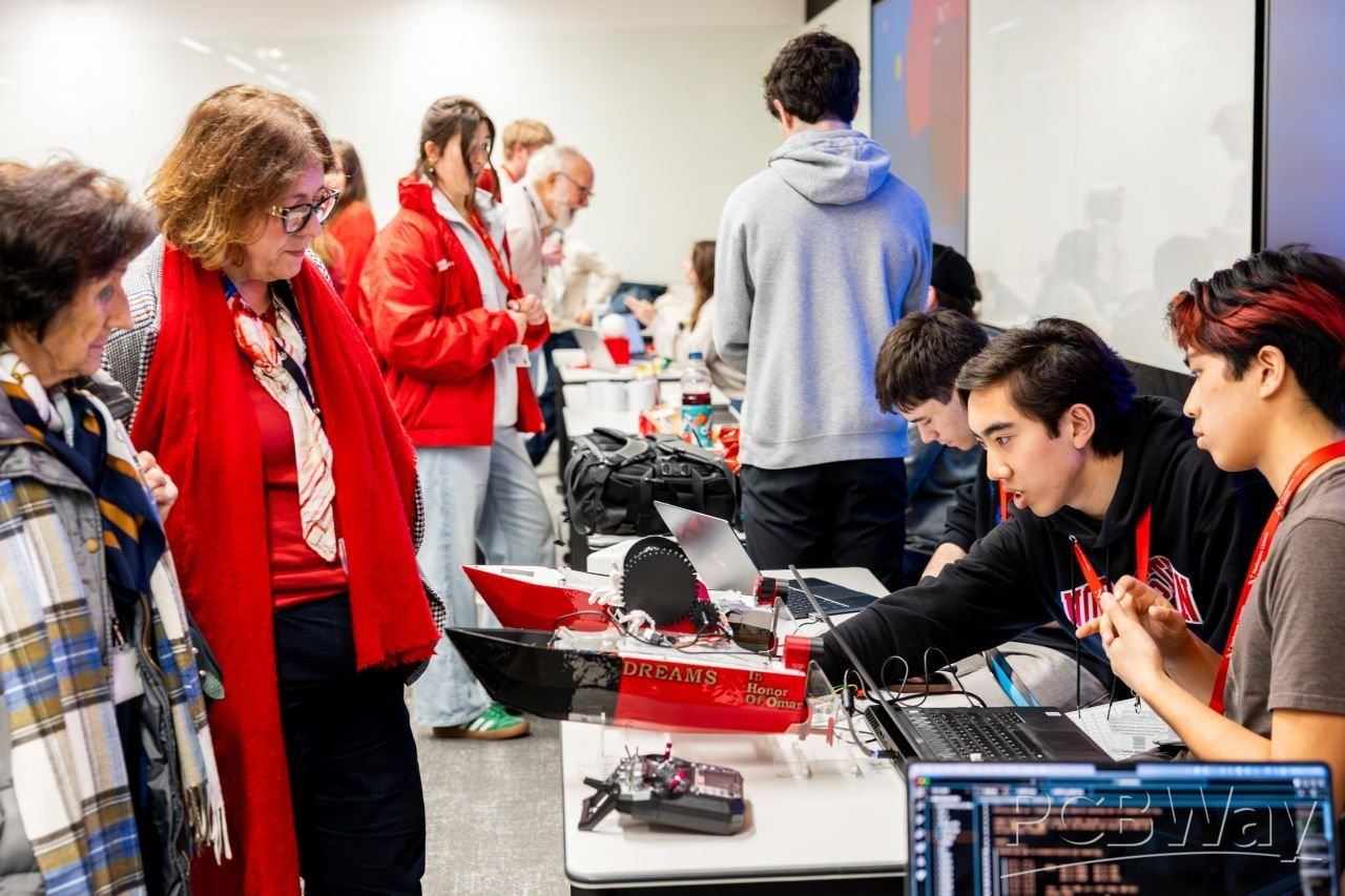
V1 at the Creators' Showcase, Northeastern University London.
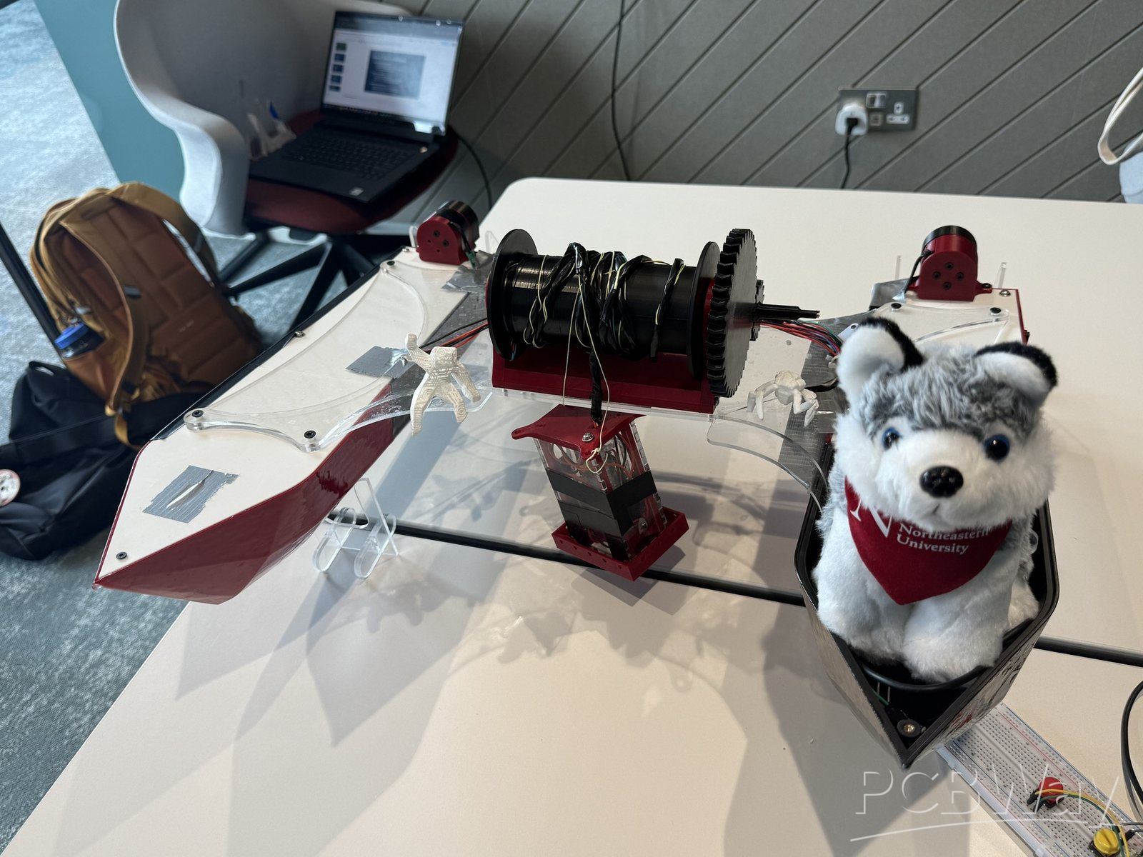
V1's bridge, the deck that ties the two hulls together, with the winch on top.
V2 (summer 2026) got a new hull, 3D-printed in sections and fiberglassed, and our first custom PCBs. It taught us what not to do: it never left the bench, because testing exposed problems in its motor control, power and safety.
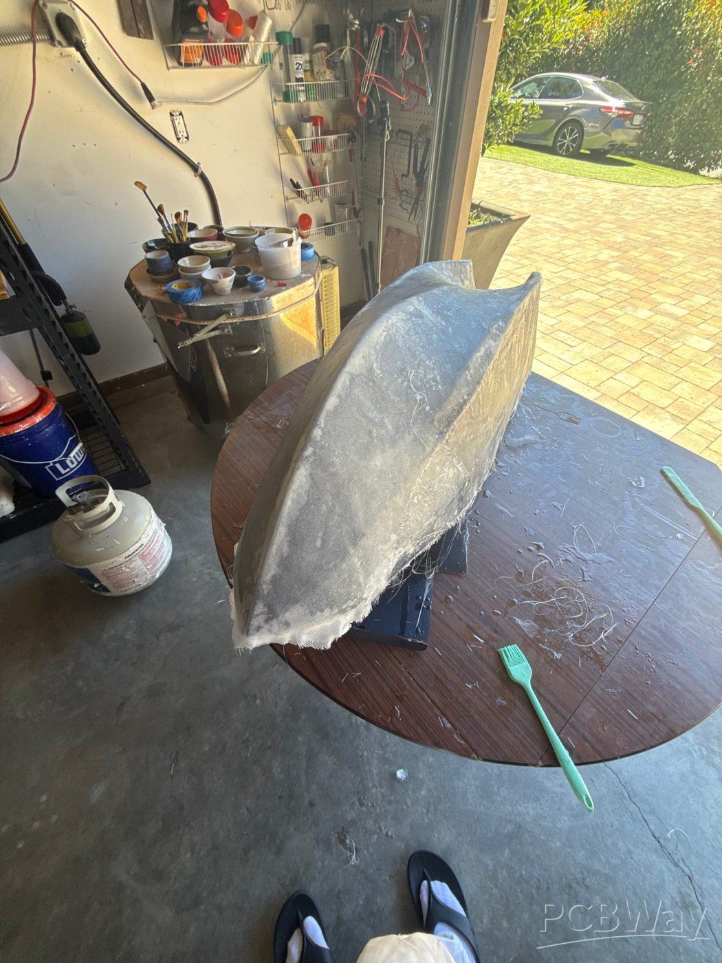
Fiberglassing the V2 hull.
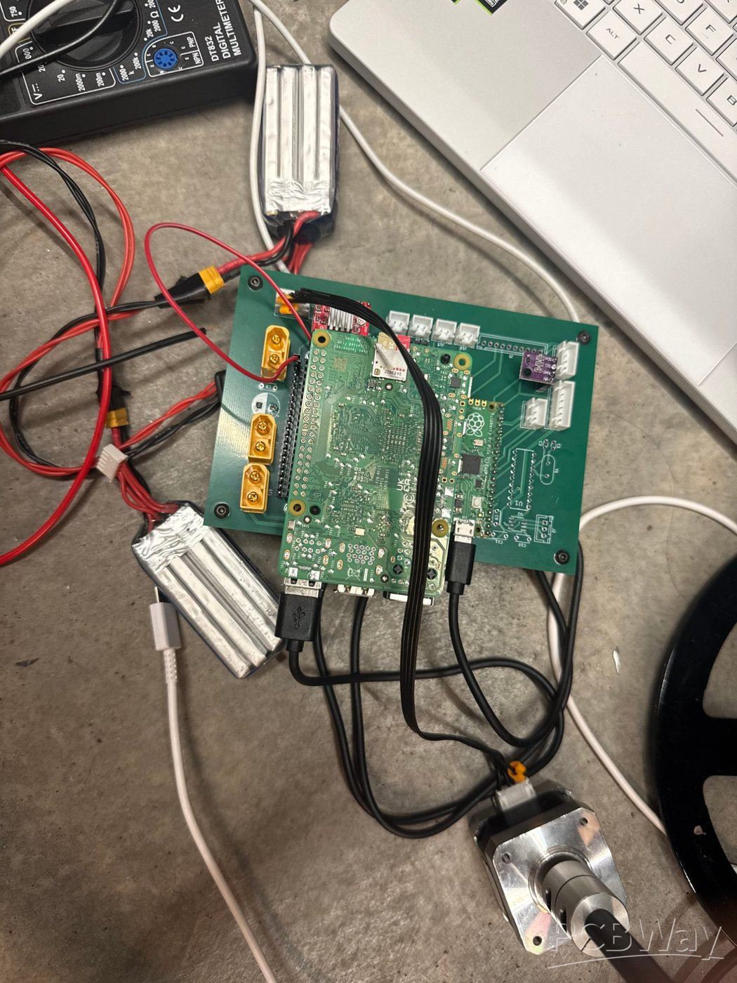
Bringing up our V2 PCB on the bench.
V3 (fall 2026) is a full redesign, with its real-time control moving to Raspberry Pi Picos. To get on the water sooner, we designed V3.1 first: a starter carrier board that runs the whole boat from a Raspberry Pi 5 and one Raspberry Pi Pico 2. It and the sensor-pod board are the two boards we're asking PCBWay to help us make.
Project description
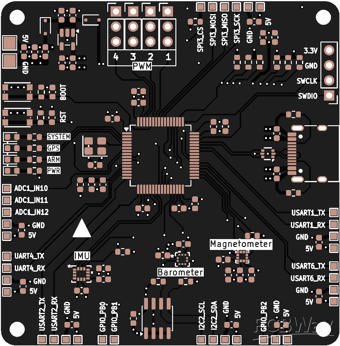
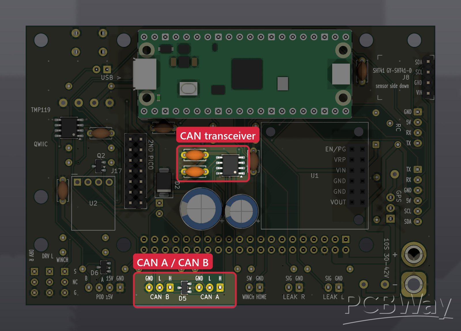
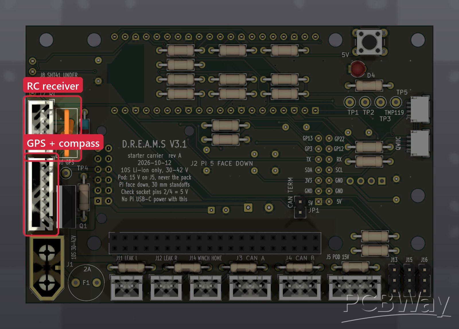
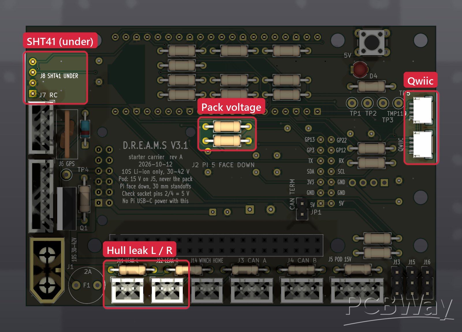
Both boards are designed in KiCad 10 and pass every check with zero errors: design rules (DRC), electrical rules (ERC) and schematic-to-layout parity. The pictures below are renders of the actual board files, with each section outlined in red.
Board 1: V3.1 starter carrier
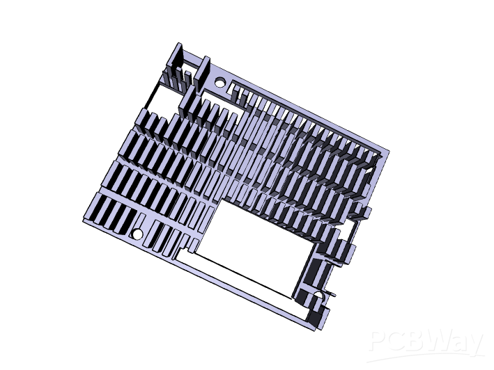
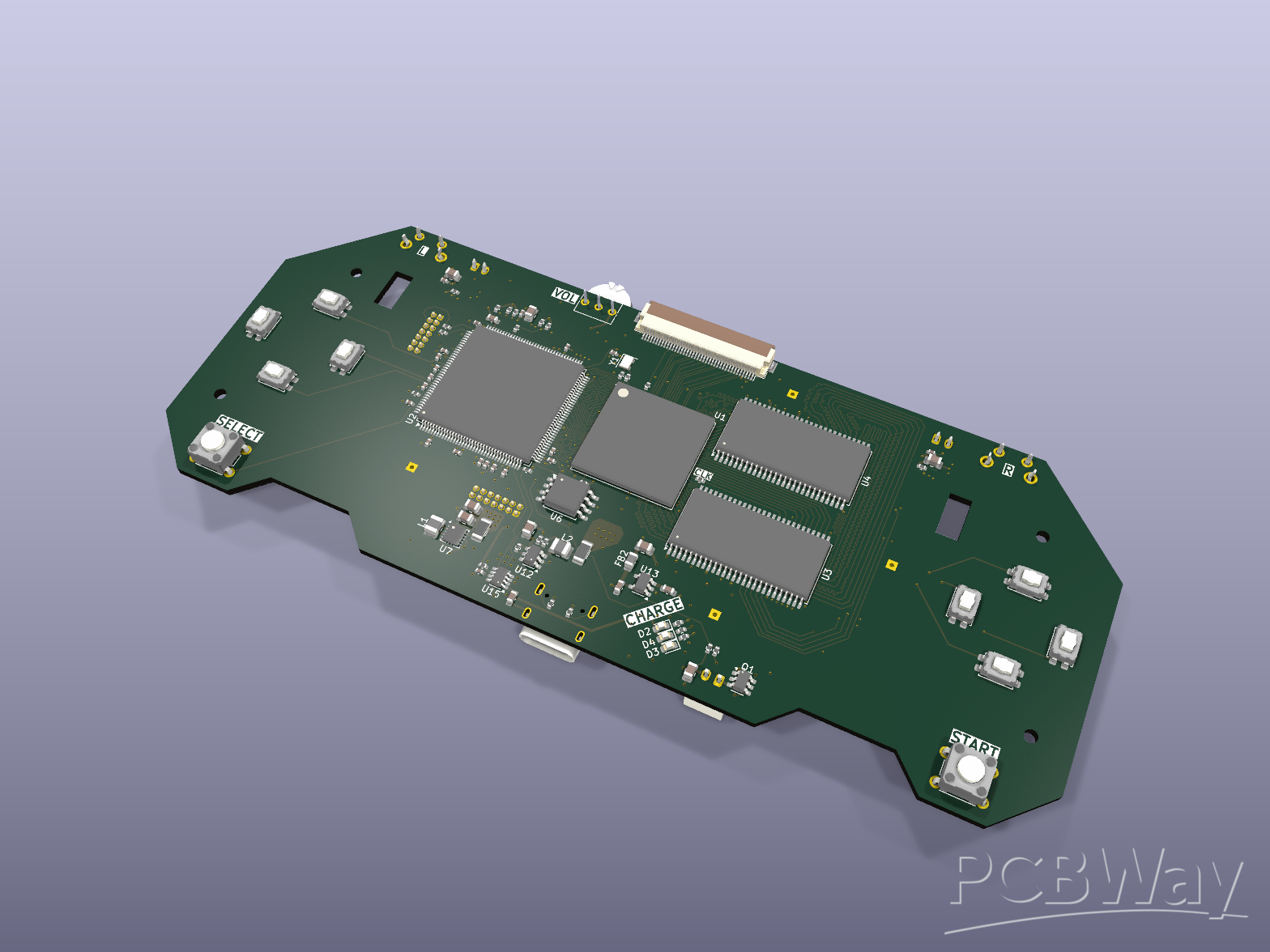
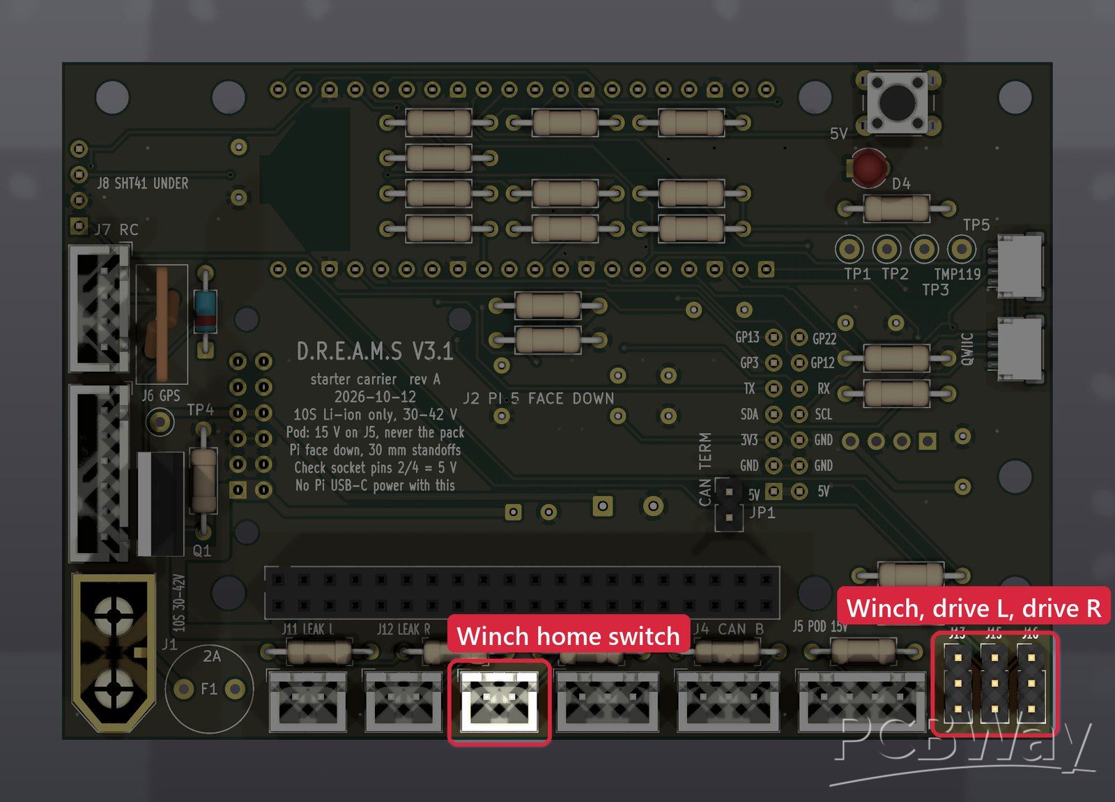
98 × 67 mm, 2 layers, 1.6 mm FR-4, ground poured on both sides, 75 footprints. The Raspberry Pi 5 plugs in face down on top, and the Pico 2 hangs underneath. All the tall parts (the Pico, both regulator modules and every capacitor) are on the underside, so nothing under the Pi is taller than about 9 mm and there's room for a heatsink between them. The XT60, the JST-XH connectors and the ESC headers sit outside the Pi, so their cables plug in with the Pi fitted.
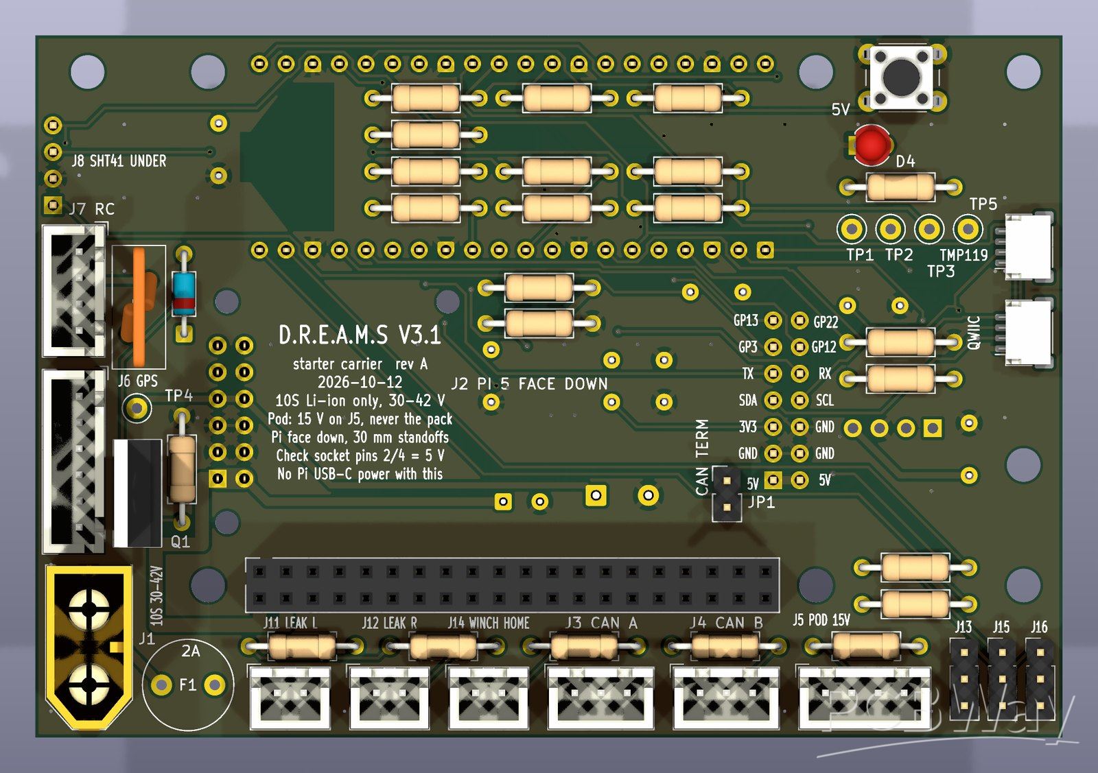
Top side.
Underside.
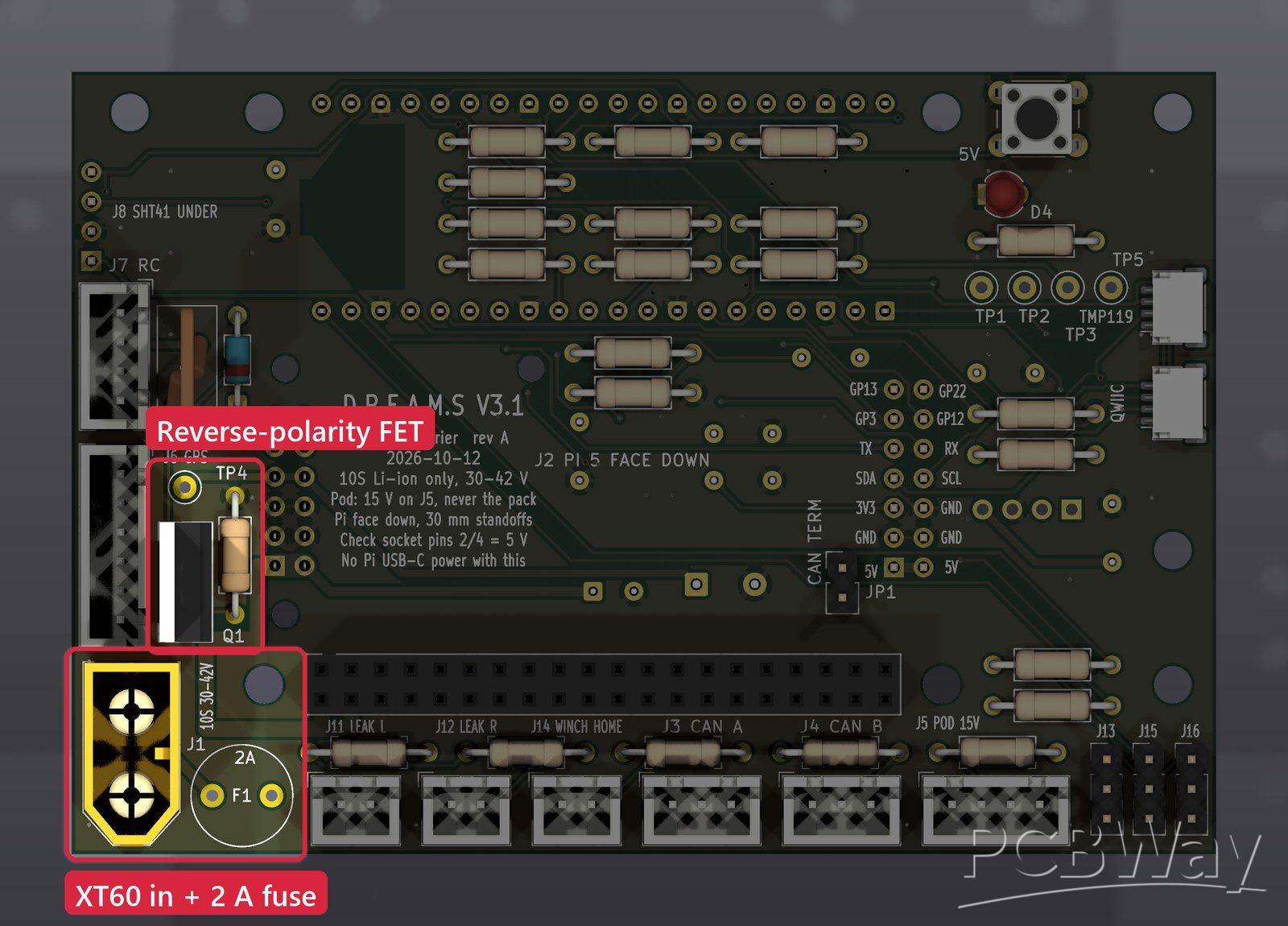
Power input and protection
One 10S Li-ion pack (30–42 V) runs the whole boat. It comes in through an XT60 connector and a 2 A time-lag fuse in a socket, so a blown fuse can be swapped. A P-channel MOSFET (IRF9540N) with a 15 V gate zener blocks a reversed battery. We added it because the 5 V regulator's own reverse protection only covers 40 V, and a full 10S pack is 42 V. On the underside, a 43 V TVS diode (SMBJ43A) and a 100 µF capacitor catch spikes on the pack, and a 100k/7.5k divider lets the Pico read the pack voltage (up to 47 V).
5 V for the Raspberry Pi 5
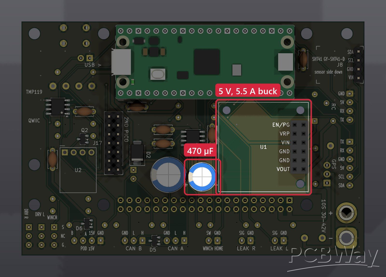
A Pololu D36V50F5 step-down regulator (5 V, 5.5 A) on the underside feeds the Pi 5 through its header's 5 V pins, plus the Pico, the GPS, the RC receiver (through its own 0.75 A fuse) and the CAN transceiver, with a 470 µF low-ESR capacitor as bulk. The Pi's 5 V pins are on the header's outer row, and the inner row can't be crossed, so the feed runs round the end of the socket on 1.3 mm of copper on both layers, good for about 5.8 A at a 10 °C rise. A green LED shows the 5 V rail is up, and test points on the 5 V, 3.3 V and pack rails make bring-up easy.
Raspberry Pi Pico 2
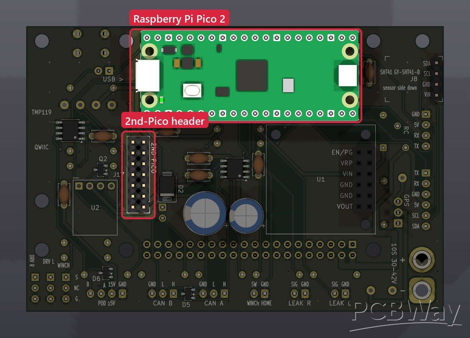
The Pi 5 runs navigation and the mission. The Pico 2 handles the real-time side: motor commands, radio control and the sensors. It's socketed on the underside, so a Pico, Pico 2 or Pico W fits (the W's antenna keep-out is kept clear of copper), and its USB end faces the Pi's USB ports so one short cable links the two and also flashes the Pico. Its 3.3 V output powers the sensors and transceivers. The full V3 will use two Picos, so a 2×7 header passes 5 V, 3.3 V, I²C, a UART and four spare pins to a second one.
CAN bus to the motor controllers
The drive motors run on two VESC motor controllers over CAN. A TJA1051T/3 transceiver connects the bus to the Pico, whose PIO runs the CAN controller in software (can2040), so no separate controller chip is needed. Two connectors daisy-chain the bus to both VESCs, a jumper switches in the 120 Ω terminator, and a NUP2105L TVS protects the bus lines.
Sensor-pod link: RS-485 and 15 V
The sensor pod is connected to the boat by a 4-wire tether. A THVD2410 RS-485 transceiver (half-duplex, terminated at this end) carries the data, and a Pololu D36V6F15 regulator makes 15 V for the pod, so the pod never sees the pack voltage. The regulator's own over-current, short-circuit and thermal protection cover a tether fault. The Pico can switch the pod off through a BSS138 MOSFET on the regulator's shutdown pin, and a resistor keeps the pod on while the Pico boots. A second NUP2105L protects the tether's data lines.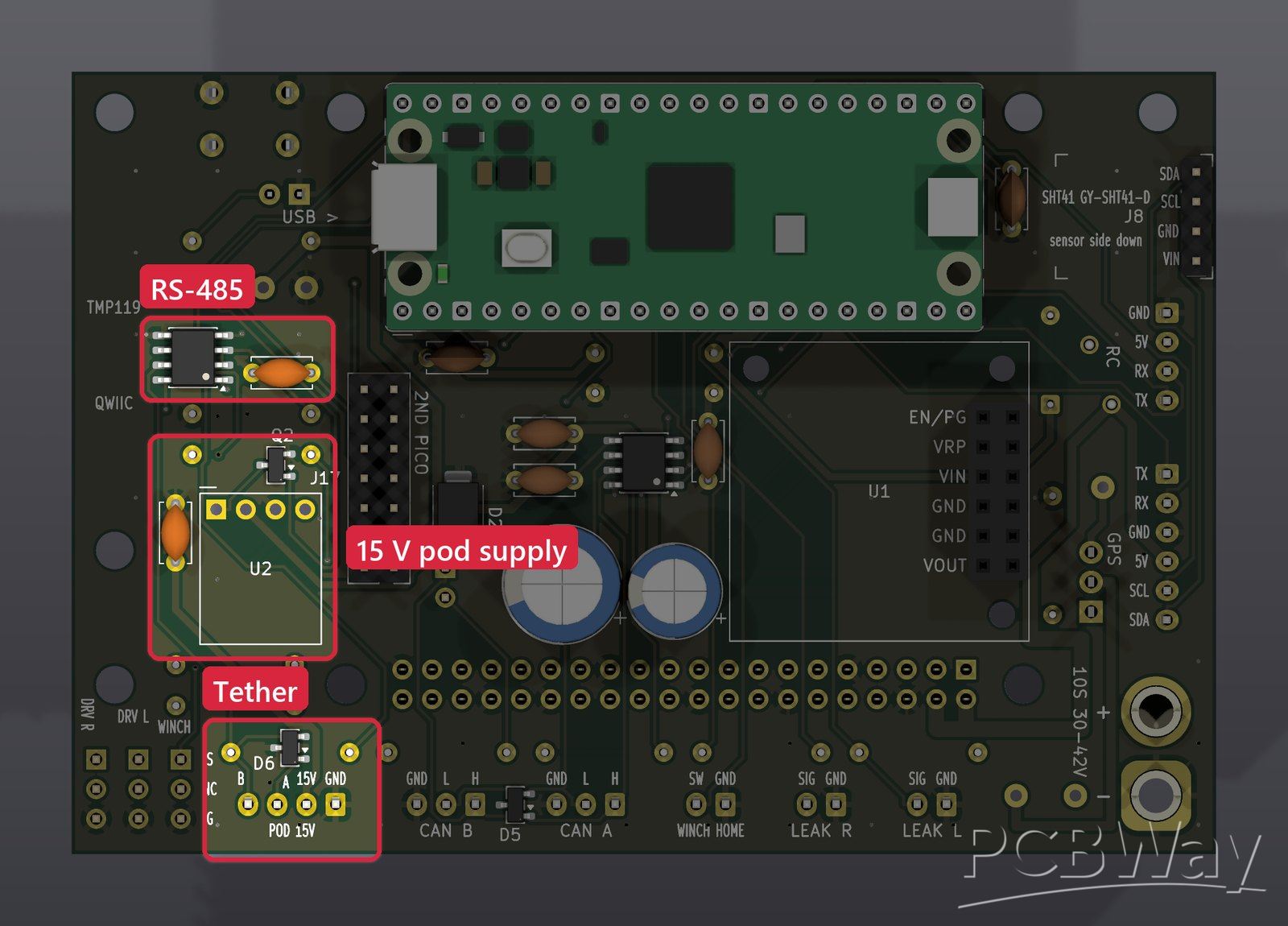
GPS, compass and radio control
The GPS module has a built-in compass: its UART runs on one of the Pico's PIO UARTs, and the compass shares the I²C bus. The RC receiver input takes SBUS (inverted inside the Pico's UART, with no extra chip) or CRSF/ELRS, so the boat can always be driven by hand.
Sensors and leak detection
An SHT41 module under the top-left corner, away from the Pi's heat, measures the air inside the hull. Two Qwiic ports take a TMP119 water-temperature sensor (potted on its cable) and a spare. Two hull leak probes are only powered while they're read: the Pico drives their excitation line high, reads both through its ADC, then switches it off again, because a probe held at DC corrodes.
ESC outputs and the winch
Three servo-style headers drive ESCs: the winch, plus left and right drive as a fallback if the drive isn't on CAN. Each signal goes through a 330 Ω resistor, and the middle pin is left open so an ESC's built-in 5 V supply (BEC) can't back-feed the board. A filtered input reads the winch's home switch.
Board 2: sensor-pod board
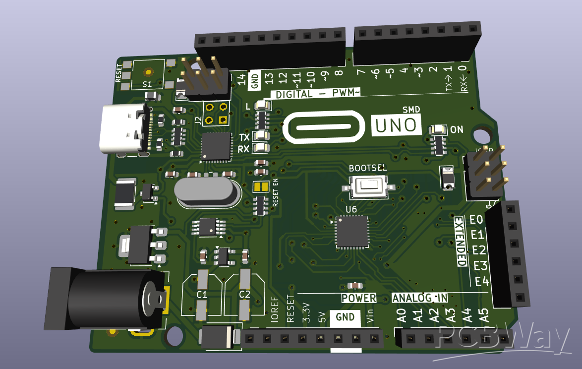
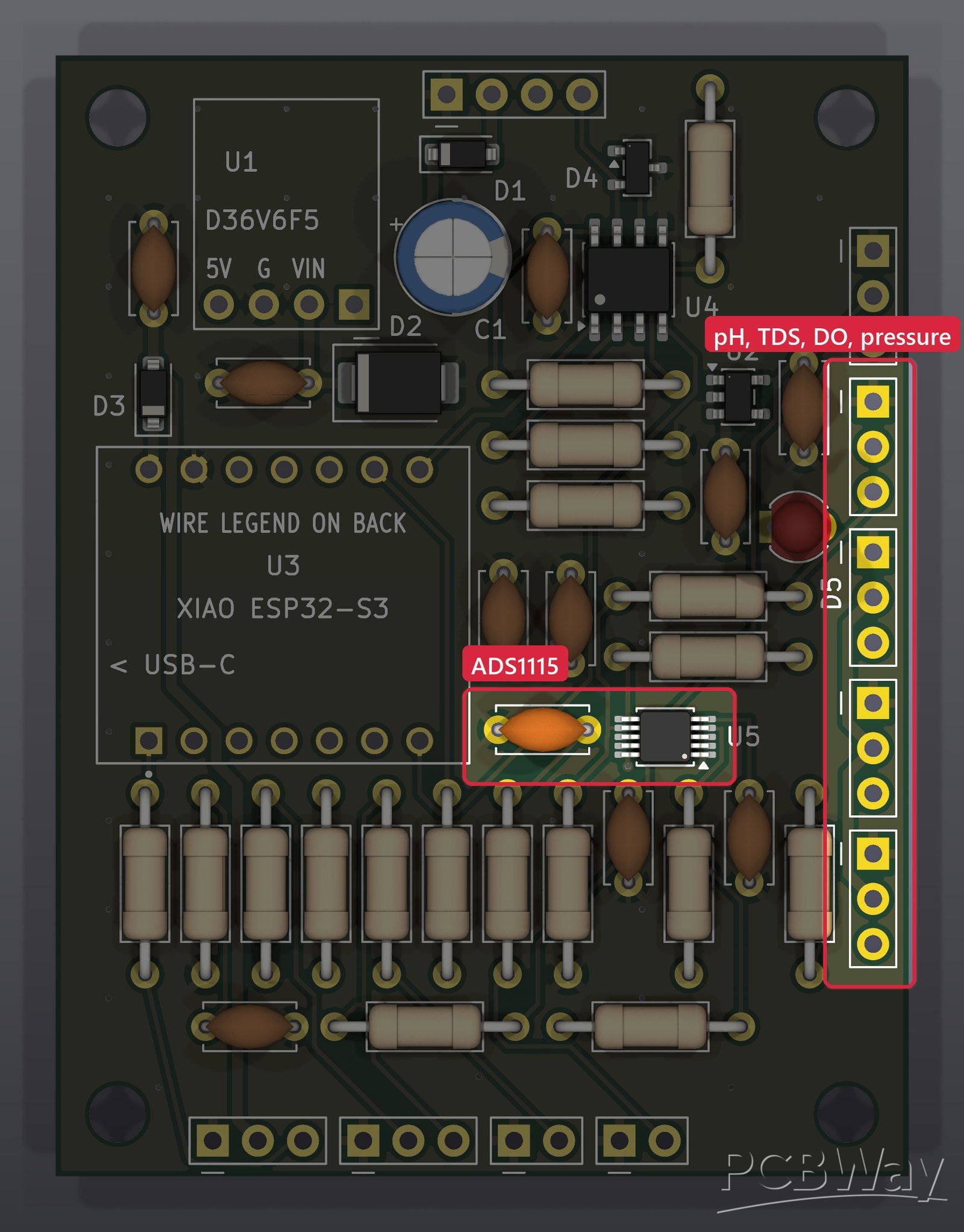
48 × 63 mm, 2 layers, 54 footprints, built for hand assembly. It rides in the tethered sensor pod, reads the water-quality probes and sends the readings up the tether over RS-485. This is rev B: a design review brought the decoupling capacitors to within 3 mm of their chips and re-placed the whole layout on a grid.
Power from the tether
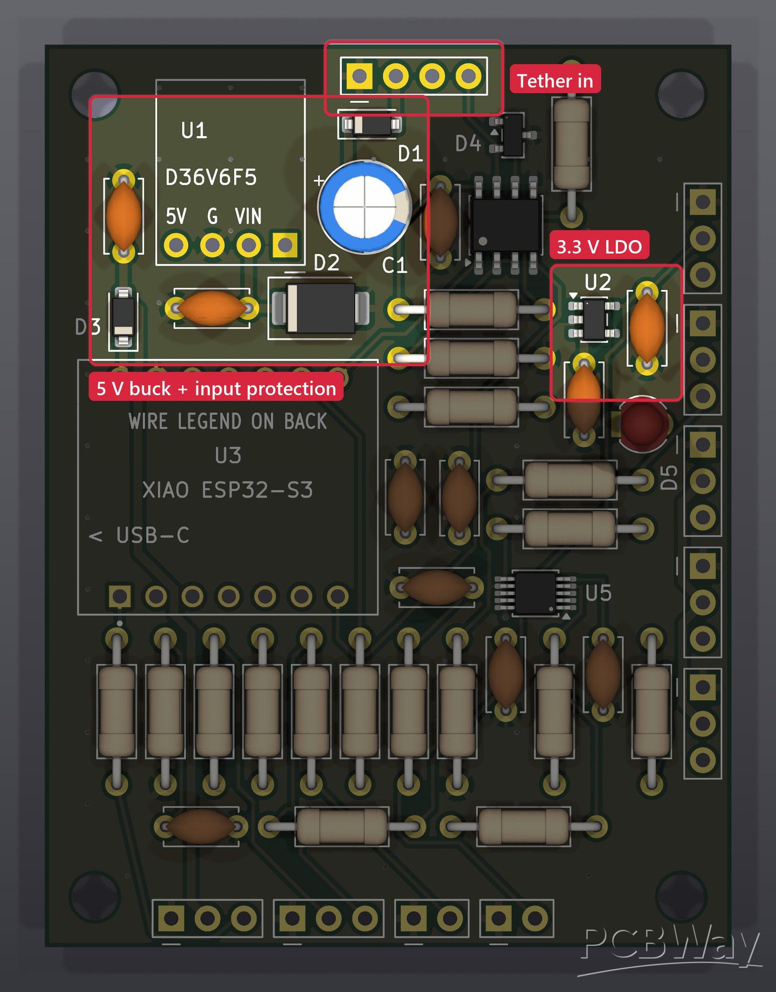
The pod takes 12–21 V from the tether; the V3.1 carrier sends 15 V. A Schottky diode and a 24 V TVS (SMBJ24A) protect the input. A Pololu D36V6F5 regulator makes 5 V for the probes, and an AP2112K-3.3 makes a clean 3.3 V for the ADC, the transceiver and the pull-ups. A diode stops the XIAO's USB port from back-feeding the 5 V rail during bench tests.
XIAO ESP32-S3
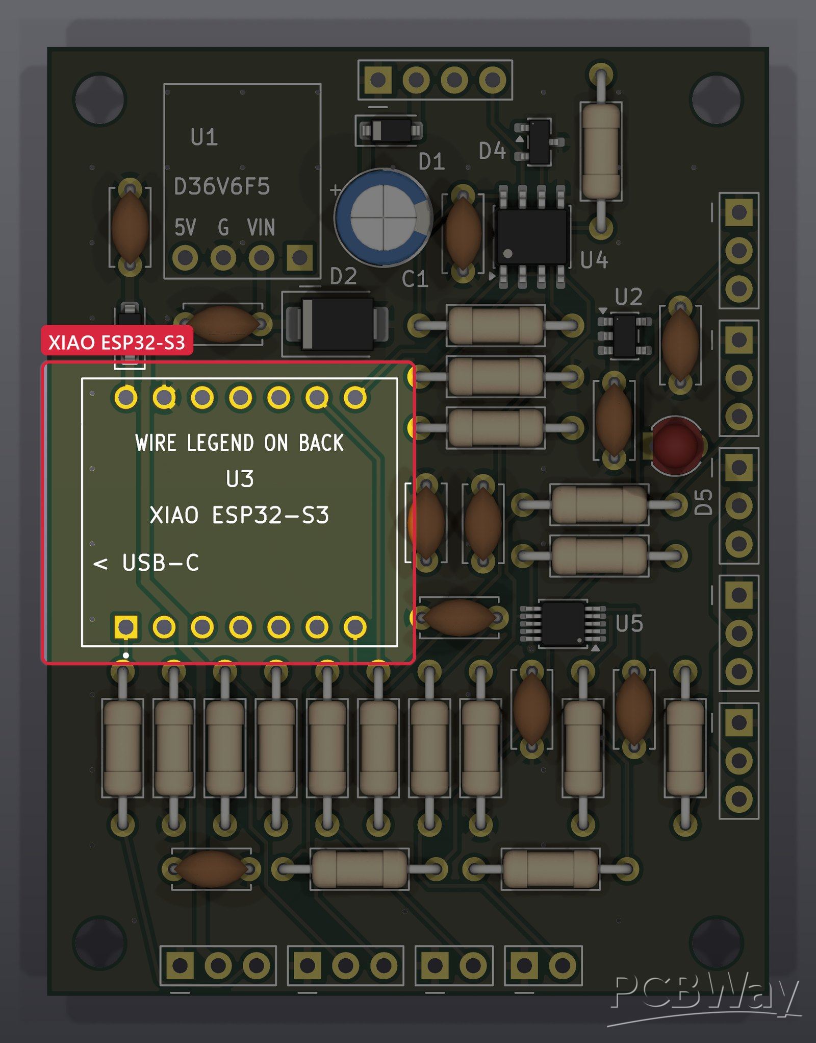
A Seeed Studio XIAO ESP32-S3 runs the pod. It sits on headers with nothing underneath, so it can be soldered straight down or socketed, and its USB-C port faces the board's edge for programming.
RS-485 transceiver
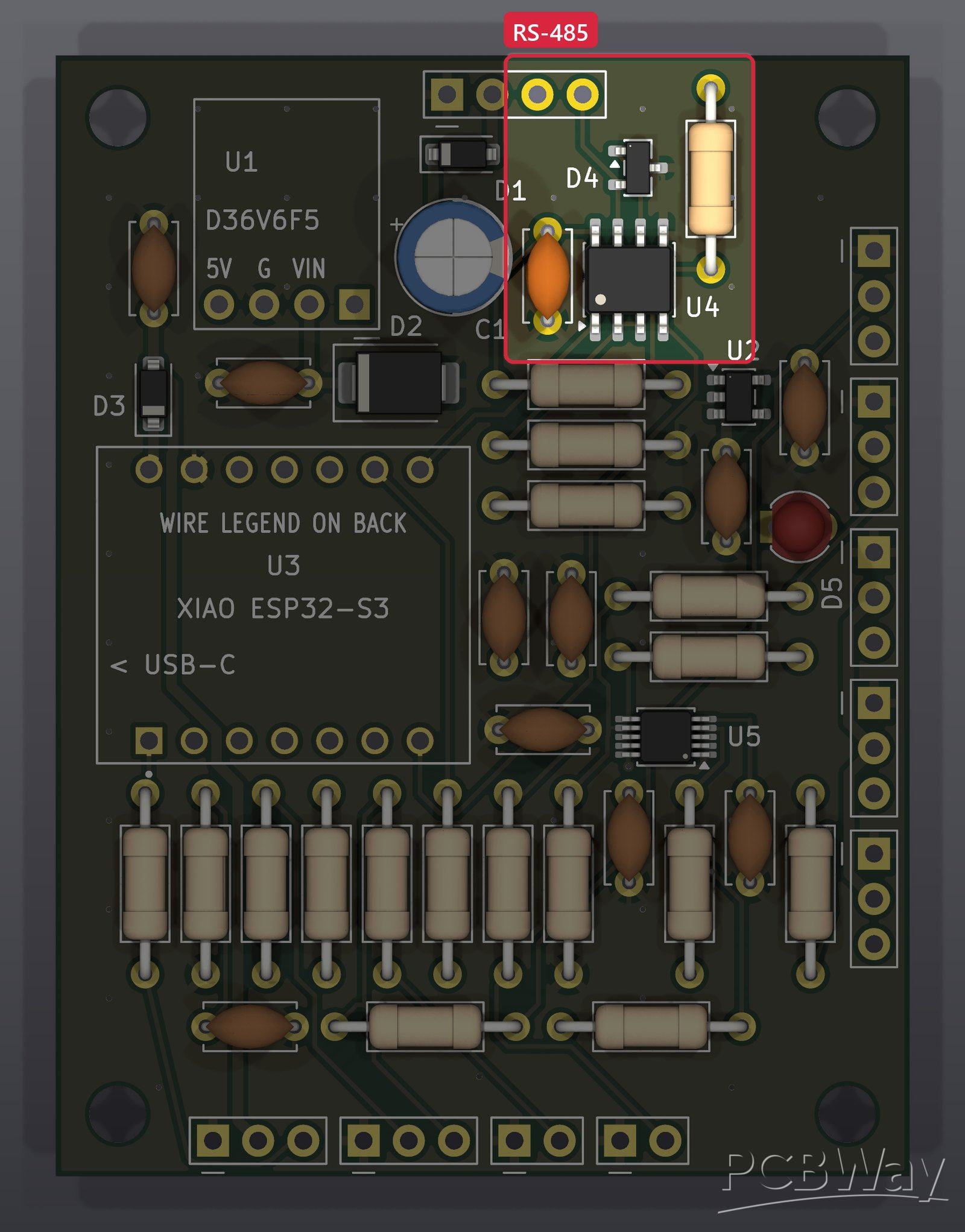
A second THVD2410 talks to the carrier over the tether, with its own 120 Ω terminator and a NUP2105L TVS on the bus lines.
16-bit ADC for the probes
An ADS1115 reads four analog probes at 16 bits: pH (DFRobot SEN0161-V2), conductivity (DFRobot SEN0244 TDS), dissolved oxygen (DFRobot SEN0237-A) and pressure (DFRobot SEN0257, divided from 4.5 V down to 3.0 V). The conductivity probe goes through a DFR0504 isolator, because its AC excitation corrupts the pH reading otherwise.
Turbidity, temperature and leak detection
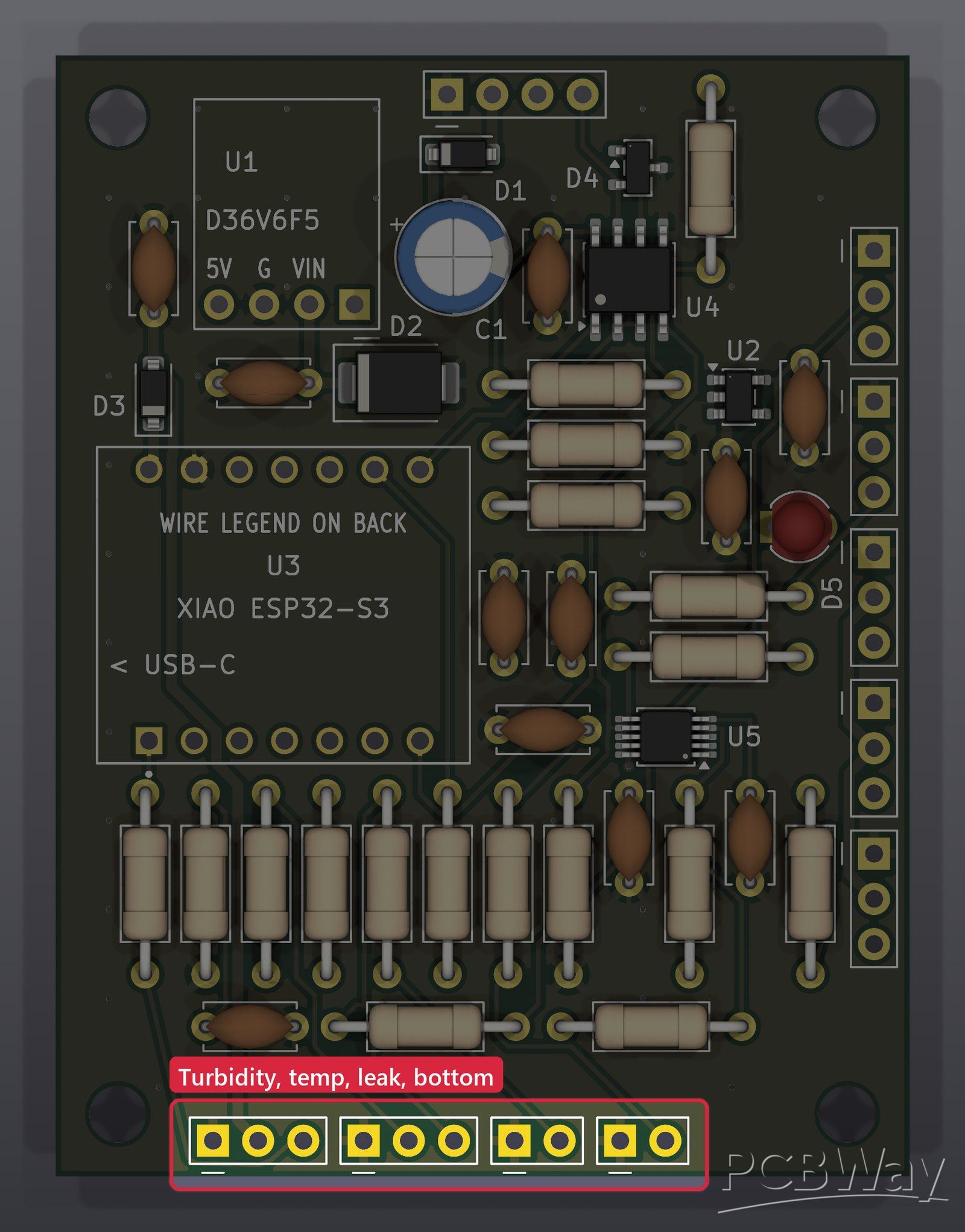
The XIAO's own ADC reads turbidity (DFRobot SEN0189) through a divider, a DS18B20 probe on 1-Wire gives the water temperature, and two inputs watch a leak probe inside the pod and a bottom-contact switch. A status LED and an aux pad group fill the last pins.
No connectors: the wires solder straight in
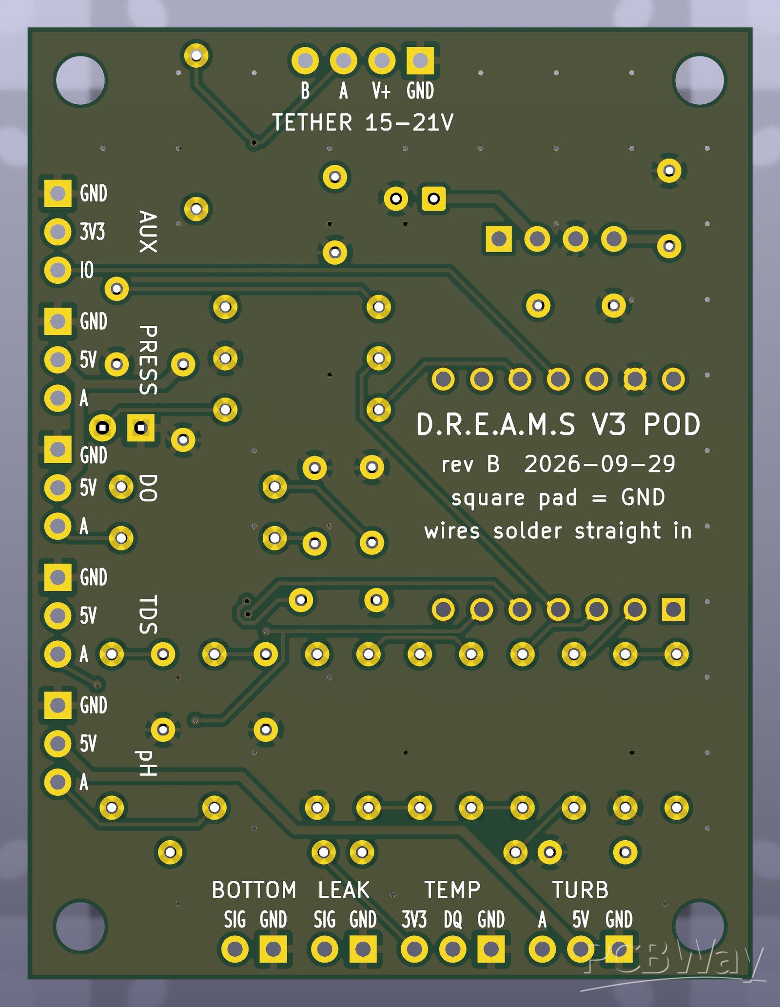
Every sensor wire solders straight into a 1.0 mm pad on a 2.54 mm pitch, so there are no connectors to work loose. The square pad in every group is ground, and the whole pin legend is on the back, which is also the side the wires are soldered on.
How PCBWay can help
Both boards are finished, checked and ready to order. We design, build and test the hardware ourselves, and fabrication is where a student team hits its limit. PCBWay's help making the V3.1 carrier and the sensor-pod board, and a few CNC-machined parts, would go straight into getting V3 on the water.
What's next
First, field trials on small bodies of water with the V3.1 carrier. Then the full V3 carrier, built around two Picos. Longer term, a robotic arm on deck that works with the winch to collect water and sediment samples.
Videos and links
V2 stereo-vision test:
V1 winch weight test: https://ka1e27.github.io/dreams/media/v1-winch-test.mp4
Full build log, photos and a 3D view of the carrier board: https://ka1e27.github.io/dreams/
Apply for sponsorship >>- Comments(0)
- Likes(0)