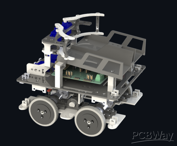
Compact ESP32-S3 Robot Controller for Robotics Projects
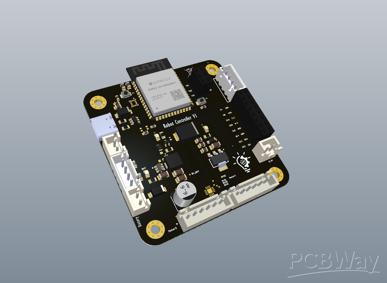
Robotics projects often require several separate modules for the main controller, motor drivers, sensors, power supplies, and communication interfaces. While this approach is useful during prototyping, it can result in complicated wiring, larger electronics, loose connections, and additional debugging.To address these problems, I designed a compact ESP32-S3 based robot controller PCB that integrates the main hardware required for mobile robotics onto a single board.
The goal of this project is to create a reusable controller that can simplify the electronics of future robotics projects and reduce the number of external modules and connections.
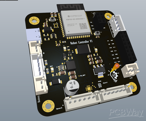
Main Controller
The board is based on the ESP32-S3-WROOM-1, which provides good processing capability, multiple hardware peripherals, and integrated Wi-Fi and Bluetooth.The ESP32-S3 acts as the central controller for motor control, encoder feedback, motion sensing, communication, and external peripherals.A USB-C interface is also included for programming and communication, together with dedicated debugging connections for firmware development.
DRV8411A Dual Motor Driver
Motor control is handled by the DRV8411A dual H-bridge motor driver.Integrating the motor driver directly onto the PCB eliminates the need for a separate motor-driver module and significantly reduces wiring.The DRV8411A provides two independent H-bridge outputs, making it suitable for controlling two brushed DC motors used in differential-drive mobile robots. The ESP32-S3 can control the motor direction and speed using digital control and PWM signals.The board also provides dedicated connections for two motor encoders. This allows the controller to measure wheel movement and enables future closed-loop functions such as:
- Motor speed measurement
- PID speed control
- Wheel position tracking
- Distance estimation
- Robot odometry
The DRV8411A also provides integrated protection features such as overcurrent protection, thermal shutdown, and undervoltage lockout, which are useful for improving the reliability of the motor-control section.This combination of the ESP32-S3, DRV8411A, and encoder inputs provides the main hardware required for closed-loop control of a two-wheel mobile robot.
ICM-42688-P 6-Axis IMU
The controller includes an onboard ICM-42688-P, which combines a three-axis accelerometer and three-axis gyroscope.The IMU can provide motion information for applications such as motion detection, orientation estimation, navigation, and sensor fusion.
Integrating the IMU directly onto the PCB removes the need for an additional sensor breakout board and makes the overall controller more compact.
Onboard Power Management
The board includes its own power-management circuitry instead of relying on separate regulator modules. It is designed to support power from both the robot battery and the USB connection, with an automatic power-path selection circuit that switches between the available power sources. This allows the board to be powered conveniently through USB during development while using the battery supply during normal operation, without requiring manual switching.
The power section generates the voltage rails required by the controller and peripherals. A switching regulator generates the 5 V rail, while a separate regulator provides the 3.3 V supply for the ESP32-S3, IMU, and other low-voltage electronics.
Power routing, source isolation, grounding, decoupling, and higher-current motor paths are important design considerations because the PCB combines motor-control circuitry, switching power electronics, digital electronics, and a sensitive IMU on the same board.
Communication and Expansion
The controller provides several interfaces for connecting additional sensors and peripherals, including UART, I²C, and GPIO connections.
The ESP32-S3 also provides integrated Wi-Fi and Bluetooth, giving the controller both wired and wireless communication capabilities.
These expansion options allow the same controller to be adapted to different robotics projects instead of being designed for only one specific robot.
4-Layer PCB Design
The controller is designed as a 4-layer PCB to provide better ground and power distribution while keeping the overall board compact.
During PCB layout, special attention is given to high-current motor paths, power distribution, grounding, decoupling capacitor placement, USB routing, IMU placement, connector accessibility, and component placement for professional PCBA.
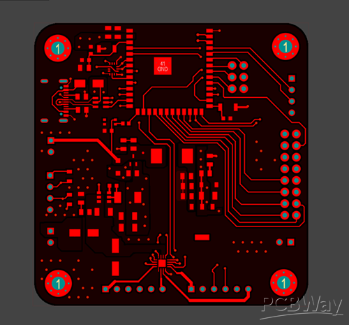
Current Status
The project is currently in the final PCB design and verification stage. The schematic and PCB layout have been completed, and the design is being prepared for professional PCB manufacturing and assembly.
The PCB has not yet been manufactured, and the next step is to produce the first PCBA revision.I am also planning to feature this project on the HP Projects YouTube channel, where I will present the motivation behind the controller, the main component selections, key hardware features, PCB design overview, and the final assembled board.
Apply for sponsorship >>- Comments(0)
- Likes(0)