CoinAI - open-hardware photometric stereo rig for coin authentication
Who I am
Donni Musmacher, United States. Self-taught, solo builder. I started this because a coin's grade is decided by surface geometry, and every tool a collector can afford only sees colour. The build is self-funded, roughly $12,000 so far with no outside investment, and I document it in depth, including the parts that failed.
What this is
A coin's grade comes down to geometry: the depth of a strike, a die crack measured in hundredths of a millimetre, wear on the highest points of the relief. A photograph flattens all of that into colour, which is why grading has stayed a manual, expensive, human job.
This machine reconstructs the surface instead of photographing it. Three cameras share one optical axis. Forty-eight individually switched LEDs sit on three illumination planes inside a light-tight enclosure. The capture fires one light at a time and solves for the surface normal at every pixel, so the result is a map of the coin's relief, not a picture of it.
It is for deciding which coins are worth paying a grading service to certify. It does not replace the certificate. It decides which coins deserve one.
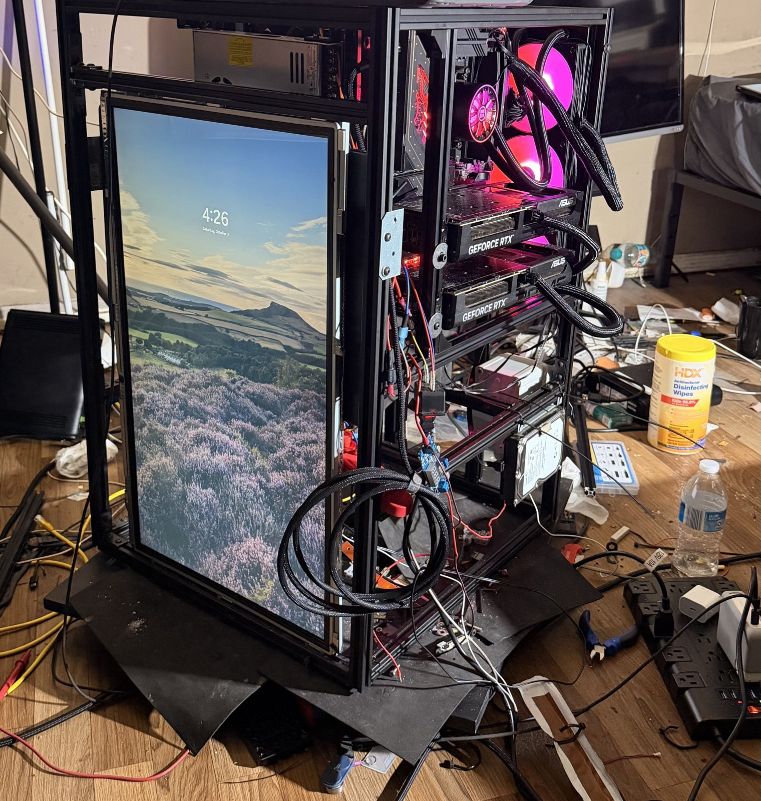
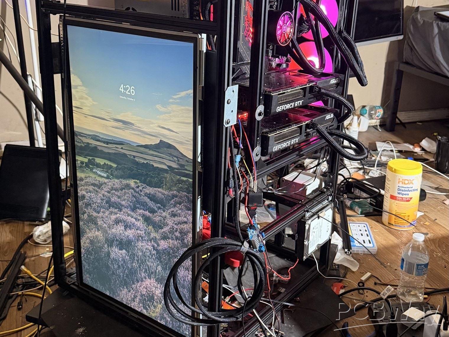
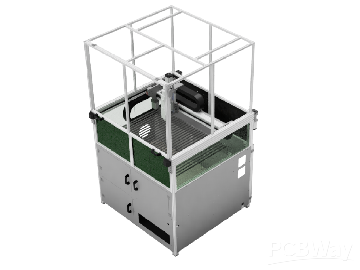
The machine as it stands, October 2026: 2020 extrusion frame, the 27-inch status panel on the front face, the compute bay beside it.
Status at a glance
- Built and working: the frame, the light-tight optical cube, three cameras on one axis, the 48-channel lighting system, power distribution and emergency stop, the compute bay, the operator panel, and the lighting watchdog.
- Designed, not yet fabricated: the centre-zone mechanism that holds and moves the coin. Rev A CAD, 21 part files.
- Proven on perfboard, not yet a PCB: three 16-channel MOSFET switching boards.
- Software: Stage 1 coin detection is trained and measured. Stages 2 to 10 are designed and not yet trained.
The rest of this page documents each of these in detail: architecture, the measurement method, the capture sequence, the lighting schematic and channel map, the mechanism design with its calculations, the bill of materials, the build log, and the exact fabrication request.
1. System architecture
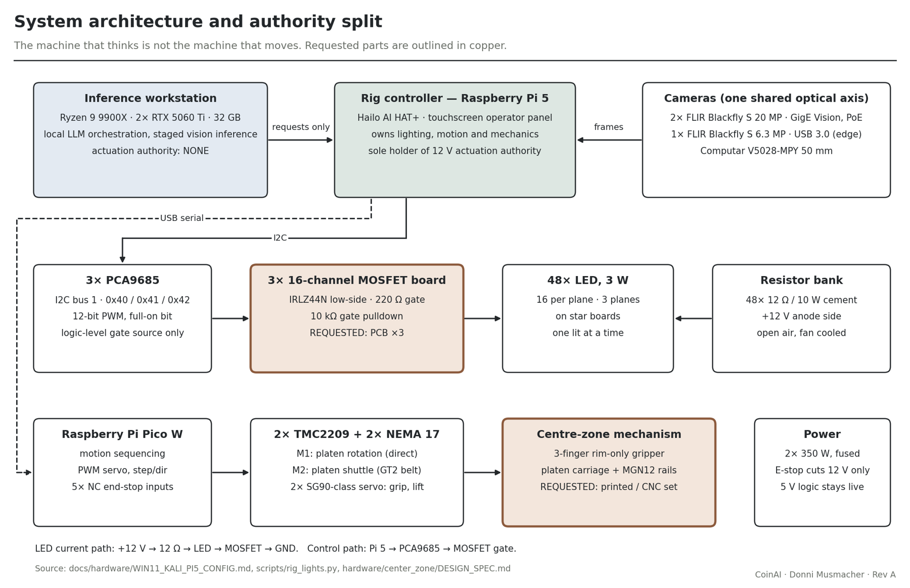
System architecture. The two blocks outlined in copper are the parts this request covers.
The rule the whole machine is built around: the machine that thinks is not the machine that moves.
- Inference workstation (Ryzen 9 9900X, two RTX 5060 Ti, 32 GB, 1000 W supply). Runs a local language model that orchestrates capture, plus the staged vision models. It has no actuation authority. Its configuration ships with lighting, motion and 12 V power disabled, and it can only send requests.
- Rig controller (Raspberry Pi 5 with a Hailo AI HAT+). Owns lighting, motion and mechanics, and is the only node that can energise the 12 V section. A touchscreen operator panel is mounted outside the optical enclosure so hardware can be adjusted without opening it.
- Motion controller (Raspberry Pi Pico W). Generates step and direction for two TMC2209 stepper drivers, PWM for two servos, and reads five normally-closed end-stop switches, under the Pi 5's command.
- Cameras. Two 20 MP FLIR Blackfly S on GigE Vision with PoE through a dedicated switch, and one 6.3 MP Blackfly S on USB 3.0 for edge imaging.
A model that misfires cannot drive a gripper into a coin, because the path from inference to actuation runs through a separate machine that has to agree to act.
Power is two 350 W supplies on a master-switched, fused distribution: 12 V to the switched section and a buck converter for 5 V logic. The emergency stop cuts the 12 V section only. Logic and monitoring stay live, so the machine can still report its own state while it is safely dead. Cooling is liquid, with the radiator built into the frame.
Nothing in the pipeline depends on a network connection or an outside service. The inference endpoint is bound to the local machine only.
2. How the measurement works
Photometric stereo lights a fixed object from several known directions and photographs it once per direction. For a matte surface the brightness of a pixel is I = albedo x (n . l), where n is the surface normal and l is the light direction. With three or more lights that is a linear system per pixel. Sixteen lights per face make it heavily over-determined (sixteen equations, three unknowns), which leaves room to down-weight frames where a pixel is in shadow or caught in a specular highlight.
The method is only as good as the lighting, which sets the design rules:
- One light at a time. The solve assumes the only light reaching the coin during frame k is light k. The capture code enforces exactly-one-on as an invariant and aborts the sweep if it is ever violated. A stack captured with two lights lit is silently unusable, which is the worst kind of bad data.
- 48 separately addressable LEDs, 16 on each of three planes, so every frame has a known, unique light vector.
- No PWM during an exposure. The PCA9685 free-runs and is not synchronised to the shutter. At its 1526 Hz ceiling one PWM period is about 655 microseconds, so a short exposure would catch a fractional period and record it as a brightness error, which the solve would read as tilt. Capture frames therefore use the chip's full-on bit: the output is held high with no chopping. Fractional levels are for bench work only, and the sweep prints a warning if asked to capture with one.
- Measured light directions. Light vectors come from a chrome-ball calibration, not from the CAD. Until a plane has been calibrated the software labels its geometry NOMINAL and warns on every capture, so an uncalibrated stack cannot be mistaken for a calibrated one.
- A light-tight, flocked black enclosure, because a stray reflection is indistinguishable from relief.
The four centre posts are one contiguous extrusion column, so all three illumination planes and all three cameras share one vertical axis by construction, not by adjustment. Only the cameras move, each on a slide and a ball joint for final aim.
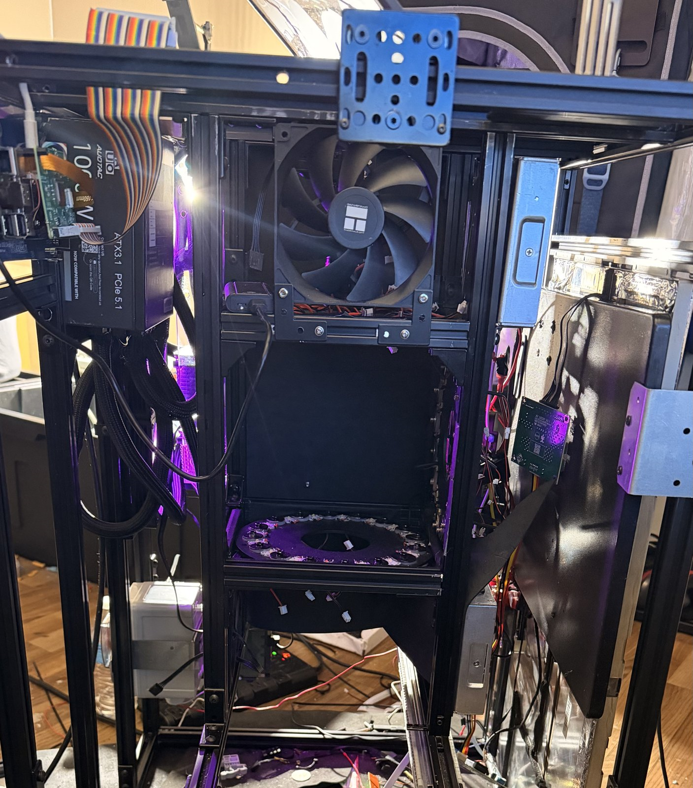
Inside the optical cube: flocked chamber, one illumination platen with its ring of 16 LEDs, and the empty centre zone the requested parts fill.
3. Capture sequence, step by step
This is the sequence the machine is designed to run. Today the coin is placed by hand; the handling steps are what the requested parts make possible.
- Place. The coin sits on a pedestal cap at HOME, a 9 mm cap for coins under 24 mm and a 16 mm cap otherwise.
- Edge pass. With the gripper open, stepper M1 rotates the platen in indexed steps (0.9 degree full steps, 1/16 microstepping, 0.056 degree resolution) while the side camera images the rim under the side plane's 16 LEDs.
- Grip. The finger servo turns the cam plate 60 degrees. Three fingers close on the rim only. Both faces stay untouched because both faces are the measurement surface.
- Lift. The lift servo raises the gripped coin 4 mm and waits 500 ms to settle.
- Clear. Stepper M2 shuttles the platen 110 mm out from under the coin to a hard stop, opening the bottom camera's line of sight.
- Capture. With the coin held in free space, each face is captured in the same grip: 16 frames from the top camera under the top plane, 16 from the bottom camera under the bottom plane, one LED per frame.
- Return. The platen drives back into the HOME hard stop at reduced current, the coin is lowered, and the fingers open.
- Solve. Each 16-frame stack is solved for surface normals and passed to the vision stages.
Steps 2 to 5 and 7, and the bottom-face half of step 6, do not exist yet. They are the reason for this request.
4. Lighting electronics: the PCB request
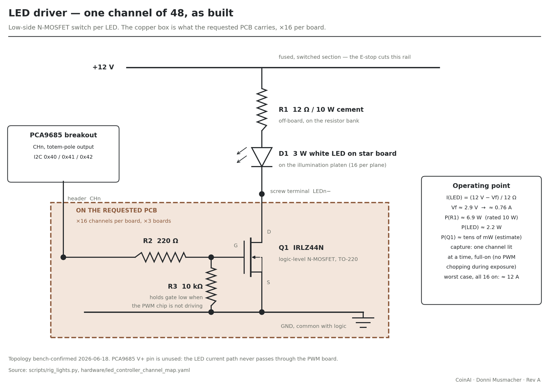
One LED channel of 48, as built. The dashed copper box is the circuit the requested PCB carries, 16 times per board.
Each LED has its own low-side switch. What each part does:
- R1, 12 ohm 10 W cement resistor, sets the LED current: (12 V - 2.9 V) / 12 ohm is about 0.76 A, and it dissipates about 6.9 W while its LED is lit. A plain resistor with a large voltage drop does a useful job here. With about 9.1 V across it, a 0.1 V drift in LED forward voltage as the LED warms changes the current by only about 1 percent, so brightness stays steady across a capture without a feedback loop.
- Q1, IRLZ44N, a logic-level N-channel MOSFET switching the LED's cathode to ground.
- R2, 220 ohm, in series with the gate. It limits the charge current drawn from the PWM chip's output and damps ringing on the gate lead.
- R3, 10 kilohm, gate to source. It holds the gate low whenever the PWM chip is not driving it: at power-up, or with its outputs disabled.
- PCA9685, used as a logic-level gate source only. Its V+ pin is left unconnected, so LED current never passes through the PWM board.
One thing R3 does not do, which I got wrong at first and then corrected in the source: it does not turn a light off if the controlling program hangs. The PCA9685 holds its last state and keeps driving the gate. That case is covered in software, described below.
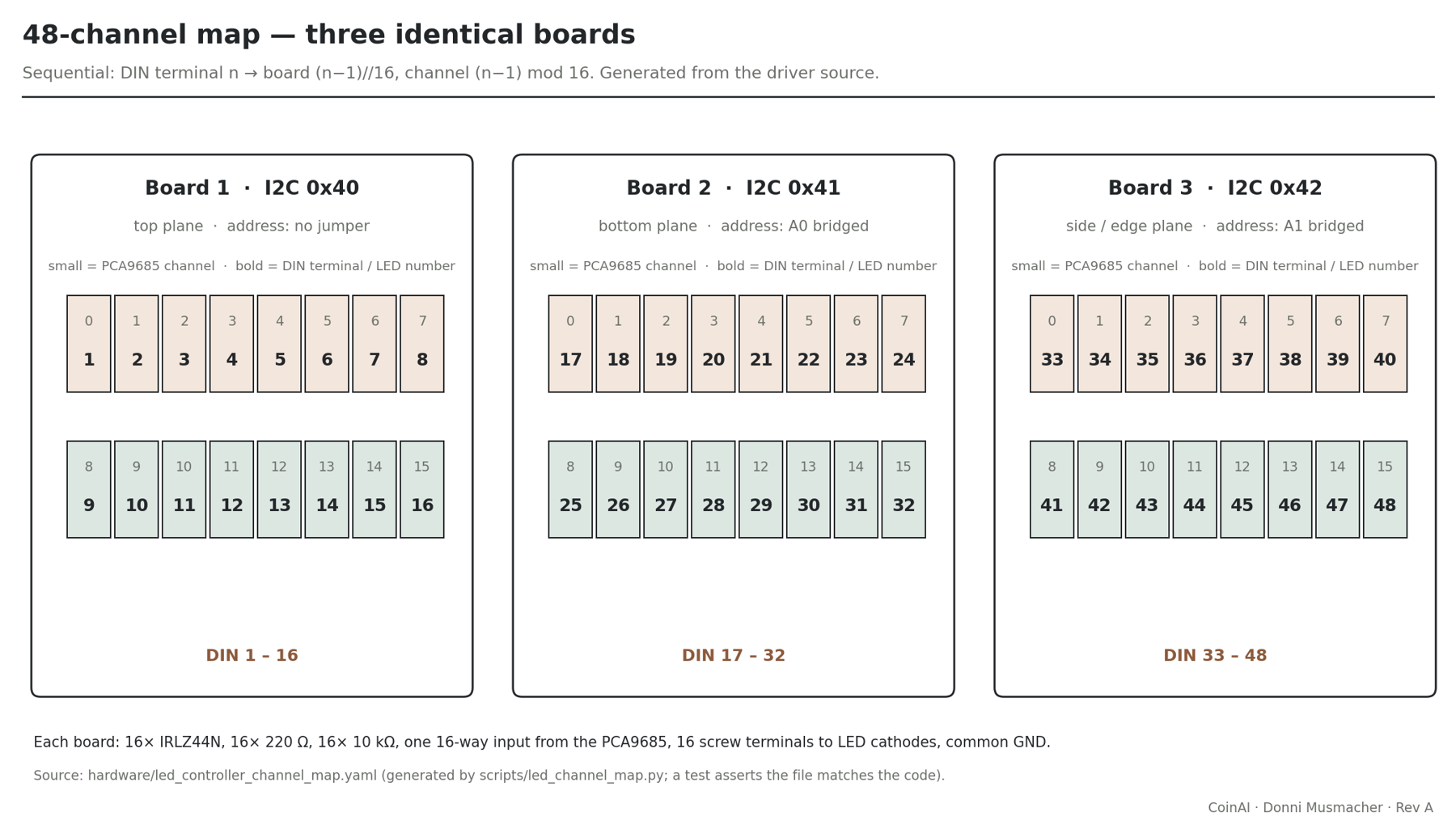
The 48-channel map. Three identical boards, one per illumination plane, addressed by solder jumper.
The map is sequential and generated from the driver source, and a test asserts that the published map matches the code. All 48 channels are wired and have been lit on the bench. The formal per-channel verification record (expected terminal against observed LED, all 48) is the next bench task.
The illumination platens. Each plane is a 200 mm disc with a 70 mm bore, laser-cut from 3.2 mm 5052 aluminium, deburred and powder-coated matte black so it does not reflect into the cameras. Sixteen LEDs sit on a 140 mm circle, with a wire pass-through behind each one. The LED stars have no mounting holes of their own, so each star sits between two M3 holes and is clamped by a screw with a 14 mm fender washer at each hole; every screw pins two neighbouring stars. Thermal paste under the star is for heat only, never for holding it. The discs themselves need no brackets: their rims sit inside the T-slots of the four centre posts and two short cross-pieces, boxed in on every side.
The LEDs run bare. Secondary optics were bought and then left off, because that optic is a lens only and needs a separate holder to mount.
What exists today. All three boards were built by hand on perfboard. They work, and they are the weakest link in an otherwise precise instrument.
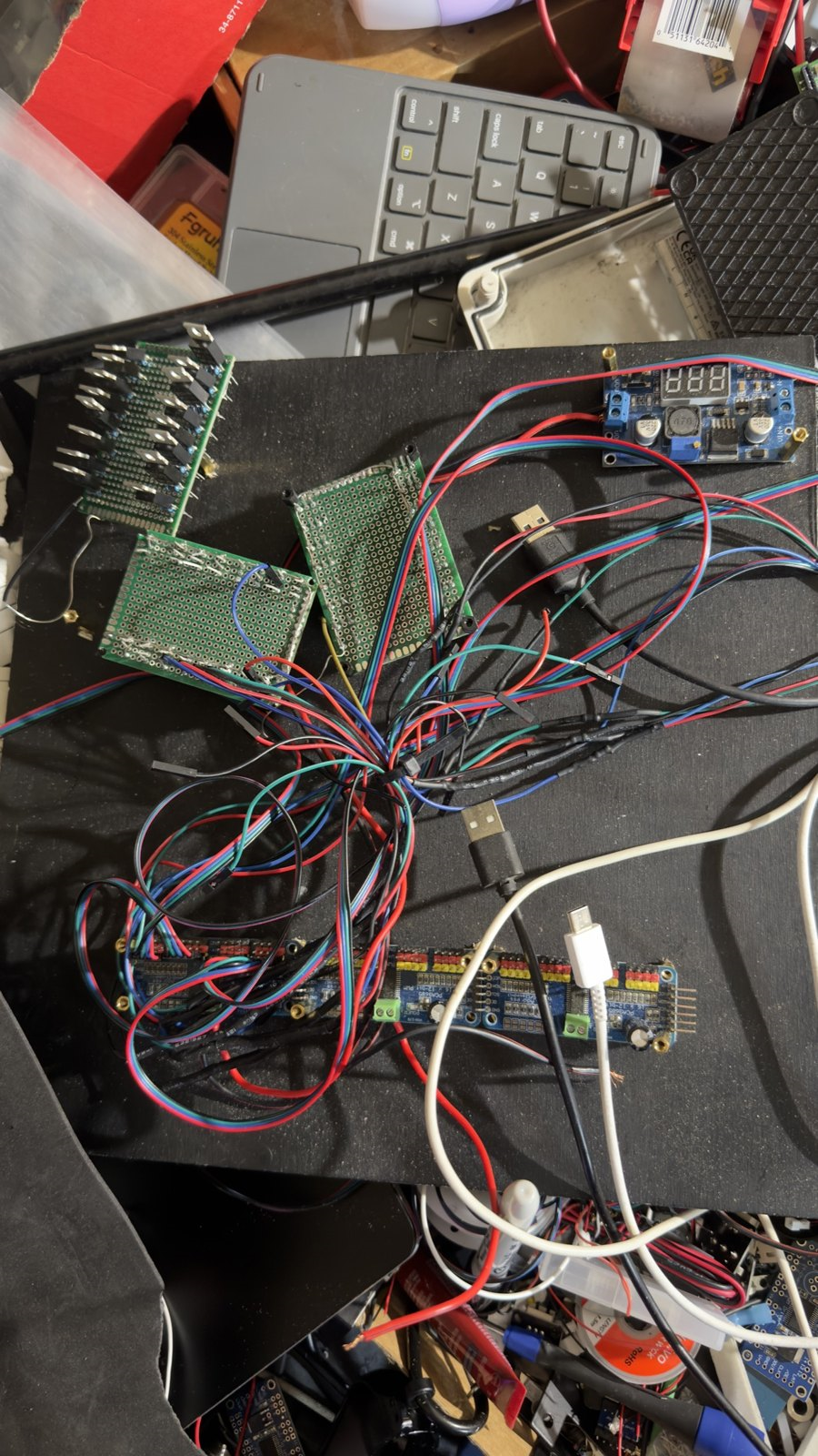
The three hand-soldered MOSFET boards and the PCA9685 controllers that drive them.
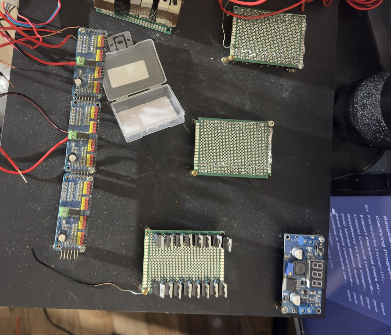
The driver set laid out: three PCA9685 boards in a column, three perfboard MOSFET banks, and the 5 V buck converter.
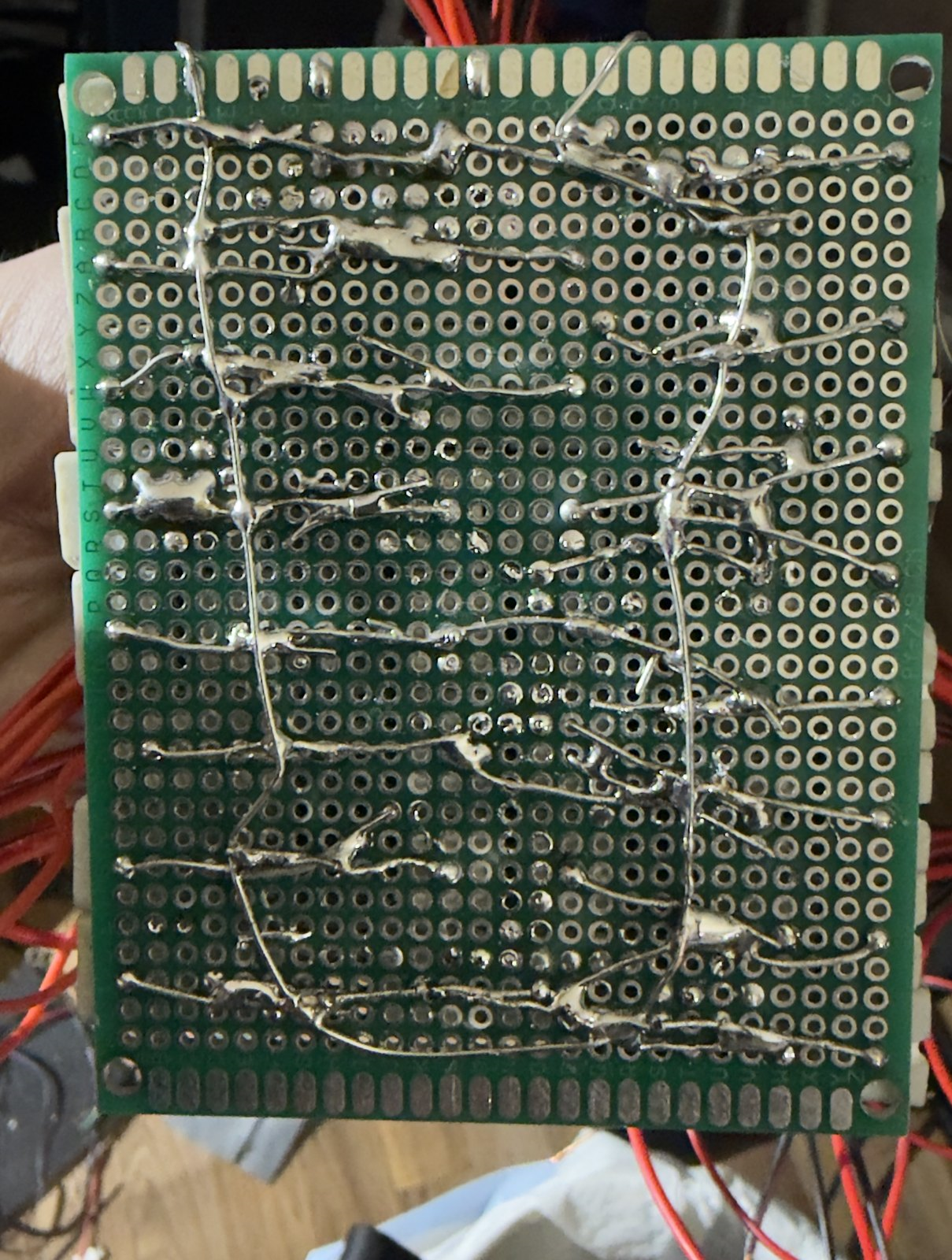
Solder side of the 48-resistor bank: the 12 V side is bussed, each LED has its own return.
Safety in firmware. The driver forces every channel off on entry, on exit, on any exception, and on Ctrl-C or a terminate signal, and it refuses to hold a single LED on for more than 30 seconds. None of that runs if the process hangs or is killed outright, so a second, independent watchdog process reads the three PWM boards twice a second and forces all 48 channels off if any channel has been lit for longer than 30 seconds, whichever program lit it. It only ever writes "off". The watchdog is covered by unit tests that run without hardware, and the driver has a dry-run mode that exercises a whole sweep with nothing attached.
What I am asking to have made:
- Three identical 2-layer boards, one per illumination plane.
- Per board: 16 x IRLZ44N (TO-220, through-hole), 16 x 220 ohm, 16 x 10 kilohm.
- Input: 16 gate signals and ground from the PCA9685 breakout's output header.
- Output: 16 screw terminals for the LED cathode returns, and a ground terminal.
- Ground return sized for the worst case of all 16 channels on, about 12 A. Normal operation is one channel, 0.76 A.
- Silkscreen at each output: PCA9685 channel number and LED terminal number, as in the map above.
- Four M3 mounting holes for standoffs.
The schematic is final and proven on the bench. The board layout is the next step, and Gerbers will be uploaded when it is complete, not before.
The resistor bank stays off the PCB deliberately. A lit channel's resistor dissipates about 6.9 W, and it belongs in open air next to a fan, not on a board beside the MOSFETs.
5. The centre-zone mechanism: the fabrication request
One empty volume sits in the middle of the machine, between the illumination planes. Everything around it is built. The mechanism that belongs in it has to satisfy these constraints, all measured on the machine:
- Interior of the optical cube: 194 x 205 x 190 mm.
- Coin diameter 12 to 42 mm, thickness 1.0 to 5.5 mm. The binding case is the smallest: a 12.7 mm coin.
- Platen: 60 mm, opaque, solid. A transparent platen was considered and rejected, because it adds refraction and surface artefacts to the very measurement the rig exists to make.
- LED discs: 200 mm diameter with a 70 mm bore, LEDs on a 70 mm radius, 101.6 mm above and below the coin plane.
- Cameras about 127 mm from the coin plane.
- Coin centred on the optical axis within 0.5 mm. HOME repeatable within 0.25 mm.
- Every printed part within 200 x 200 mm. There is no printer on site, so every part comes from a fabricator.
The coin range is deliberate. 12.7 mm is the 1849 to 1854 Type 1 gold dollar, the smallest coin the United States has struck. 42 mm covers the early silver dollars, crown-sized world issues and the thick George III cartwheel coinage.
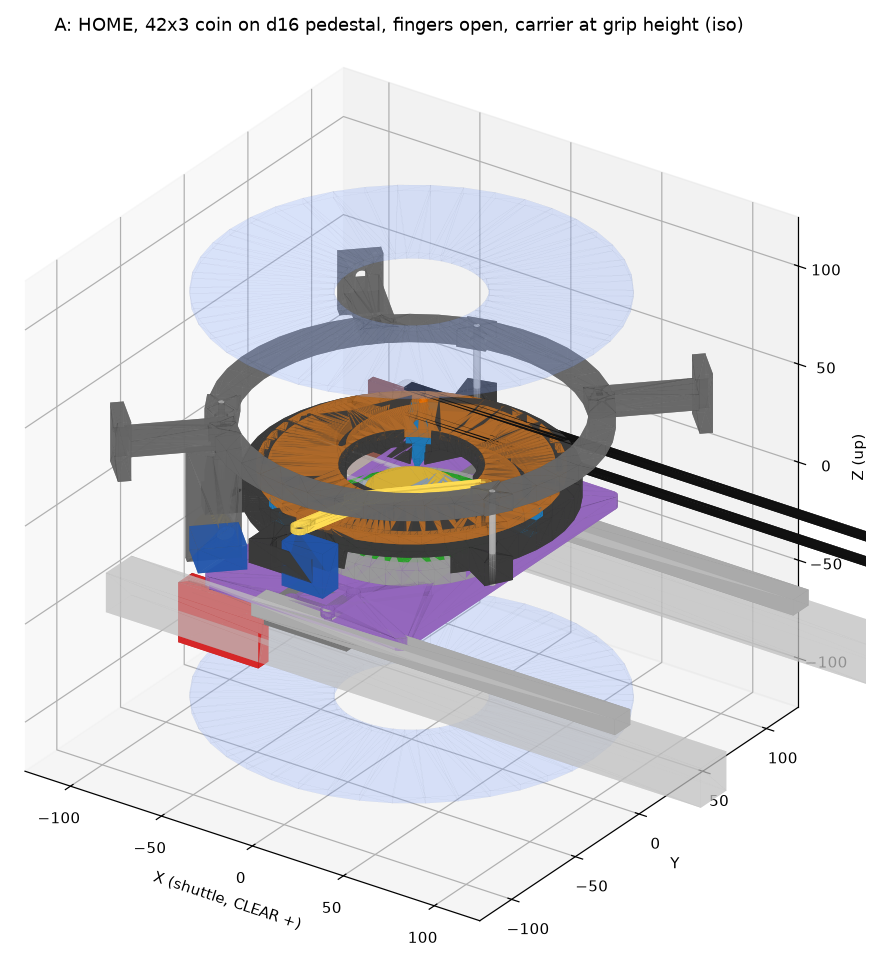
Rev A CAD, coin on the platen at HOME with the fingers open. Grey: fixed stator ring and arms. Brown: carrier ring and cam plate. Purple: platen carriage on its two rails.
Gripper
Three radial fingers slide in T-slots in a carrier ring (60 mm bore, 154 mm outside diameter, 12 mm thick). A cam plate above it carries three Archimedean spiral slots, and each finger has a follower pin riding in one slot:
- Cam profile r = 37 + 21.49 x theta (mm, theta in radians), with a 60 degree working stroke and 4 degrees of over-travel at each end.
- Finger tip radius runs from 28 mm open to 5.5 mm closed. Open clears a 42 mm coin by 7 mm. Closed reaches a 12.7 mm coin with 0.85 mm of spring over-travel.
- Pressure angle is 30 degrees closed and 19 degrees open, below the roughly 35 degree self-locking limit for PETG on PETG.
- Each finger is pre-loaded inward by a 4 x 10 mm compression spring, so grip force is set by the spring, not by servo torque. A stalled servo cannot crush a coin.
- Finger tip: a 120 degree V-notch 0.9 mm deep, which centres the coin's edge for any thickness in range.
- At the closed radius, adjacent tips are 9.5 mm apart against a 2 mm tip width, so they cannot collide.
The cam plate is turned by an SG90-class servo through a crank and link (32 mm arm, 60 mm link). The linkage was grid-searched for monotonic motion with no toggle point: 103.5 degrees of servo sweep gives the 60 degree cam stroke, and the link never sits more than 29.6 degrees off the cam tangent.
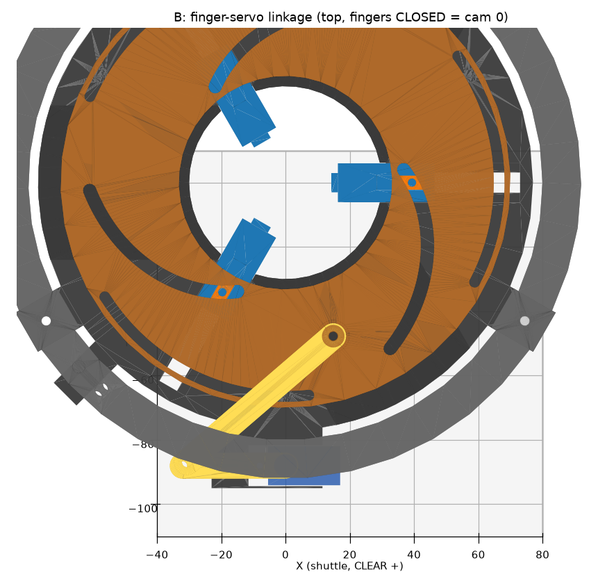
Rev A CAD, top view with the fingers closed on a 12.7 mm coin: three spiral cam slots, the finger followers (blue), and the servo crank and link (yellow).
Lift
A second servo turns an 18 mm eccentric with 5 mm offset under a lug on the carrier ring, and three 3 mm guide pins keep the carrier coaxial within 0.1 mm. Stroke is 4 mm. The carrier, cam and fingers weigh about 0.25 kg, so the holding torque is about 0.25 kg x 9.81 x 5 mm = 0.012 N.m against 0.18 N.m available from the servo, a 15 times margin. A servo fits here because the motion has two positions and almost no load. A stepper and leadscrew would add mass to the optical stack for nothing.
Rotation stays on the platen. Stepper M1 drives it directly under a 100 mm lazy-Susan bearing, because the edge pass needs indexed, repeatable angles and continuous rotation, which a servo cannot give. Rotating the gripper ring was rejected: it would put a 154 mm rotating mass with a servo and wires on the moving side and need a slip ring.
Platen stack and coaxiality budget
Pedestal cap, platen disc, hub, bearing, carriage plate, with M1 hanging below the plate. The 0.5 mm coaxiality budget is spent as: motor shaft to hub bore 0.05, hub to disc pocket 0.10, cap to disc 0.10, plate to rails 0.10, HOME stop 0.15. That is 0.50 mm worst case and about 0.24 mm as a root-sum-square.
Vertically, the coin plane has to land within 0.3 mm for focus. The stack-up is 0.55 mm worst case, about 0.27 mm root-sum-square, and the stator arms have slotted mounts with 6 mm of one-time adjustment to zero it out.
Shuttle
- Guide: two MGN12 rails, 200 mm, with MGN12H blocks, on 2020 members 70 mm either side of the optical axis. Rods with LM8UU bearings were rejected: 0.05 to 0.1 mm of radial play would eat half of the 0.25 mm HOME budget.
- Stroke: 110 mm from HOME to CLEAR.
- Drive: GT2 6 mm belt on 20-tooth pulleys, motor at the CLEAR end, idler at HOME with 20 mm of tension slot. A leadscrew was rejected: 110 mm in a second needs about 800 rpm on a T8x8 screw, and the belt's repeatability does not matter because of the next point.
- HOME is defined by a hard stop, not by the belt or a switch. M2 drives the carriage into a rubber-padded stop block at reduced current. A normally-closed micro-switch trips 1 mm before the pad, for homing and as a safety input. A second stop block defines CLEAR.
- Nothing is drilled into the frame. Every interface is a standard 2020 drop-in T-nut.
Optical keep-out
No part of the mechanism may shadow an LED or enter a camera's view, with the platen at HOME or at CLEAR. Only the three finger tips are allowed inside the cones.
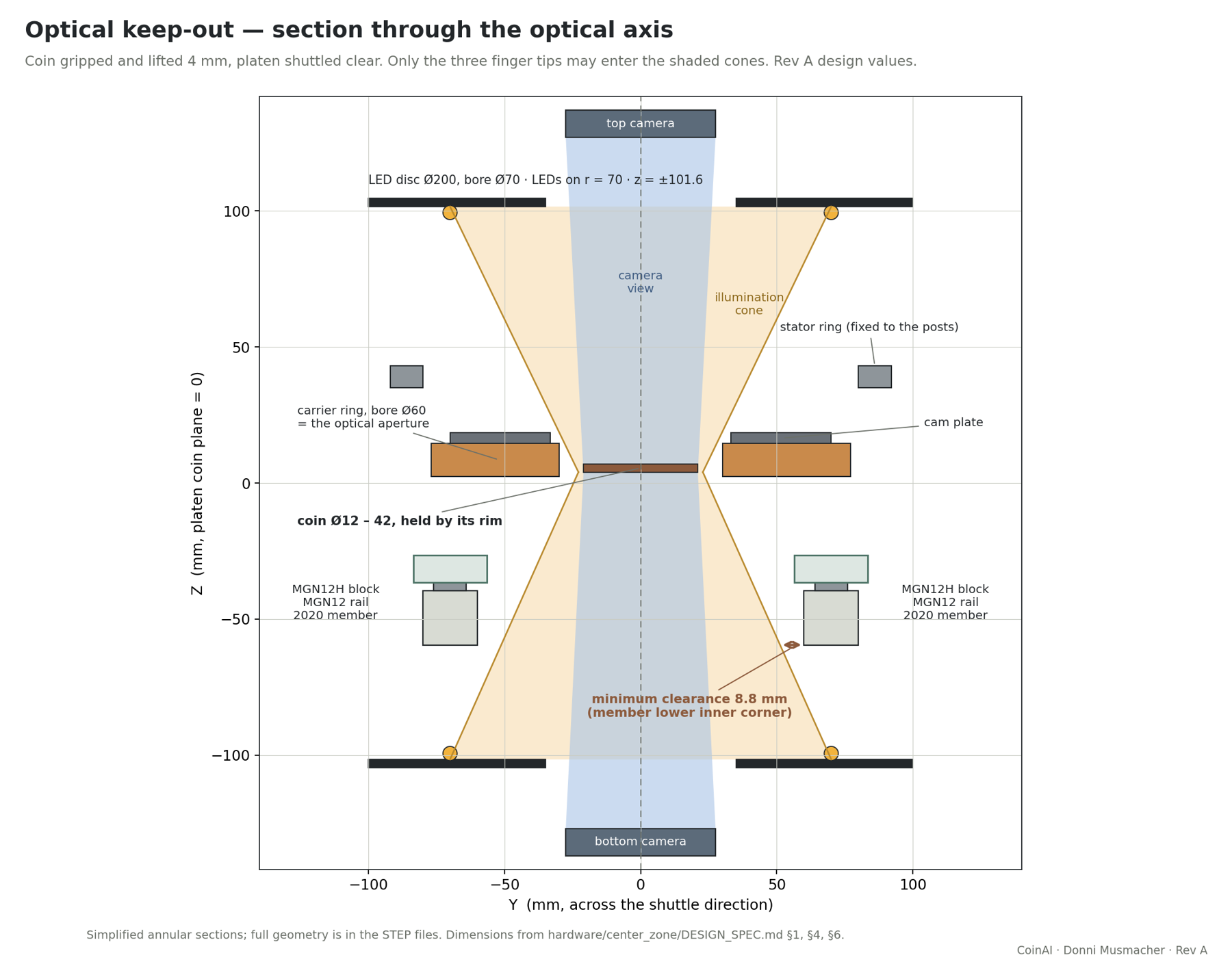
Section through the optical axis with the coin gripped, lifted and the platen shuttled clear.
The carrier ring's 60 mm bore is the optical aperture: the top illumination cone and the top camera's view both pass through it. Below the coin, the closest fixed part to the bottom illumination cone in this section is the lower inner corner of the 2020 members that carry the rails, at 8.8 mm. These are Rev A design values. They are being checked on the machine itself, with a taut string from an LED to the coin edge, before any file is released.
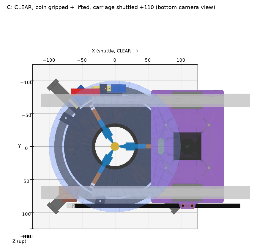
Rev A CAD, the bottom camera's view at CLEAR: the platen and carriage (purple) have shuttled 110 mm aside and the coin hangs on three finger tips in the open bore.
Fabricated parts
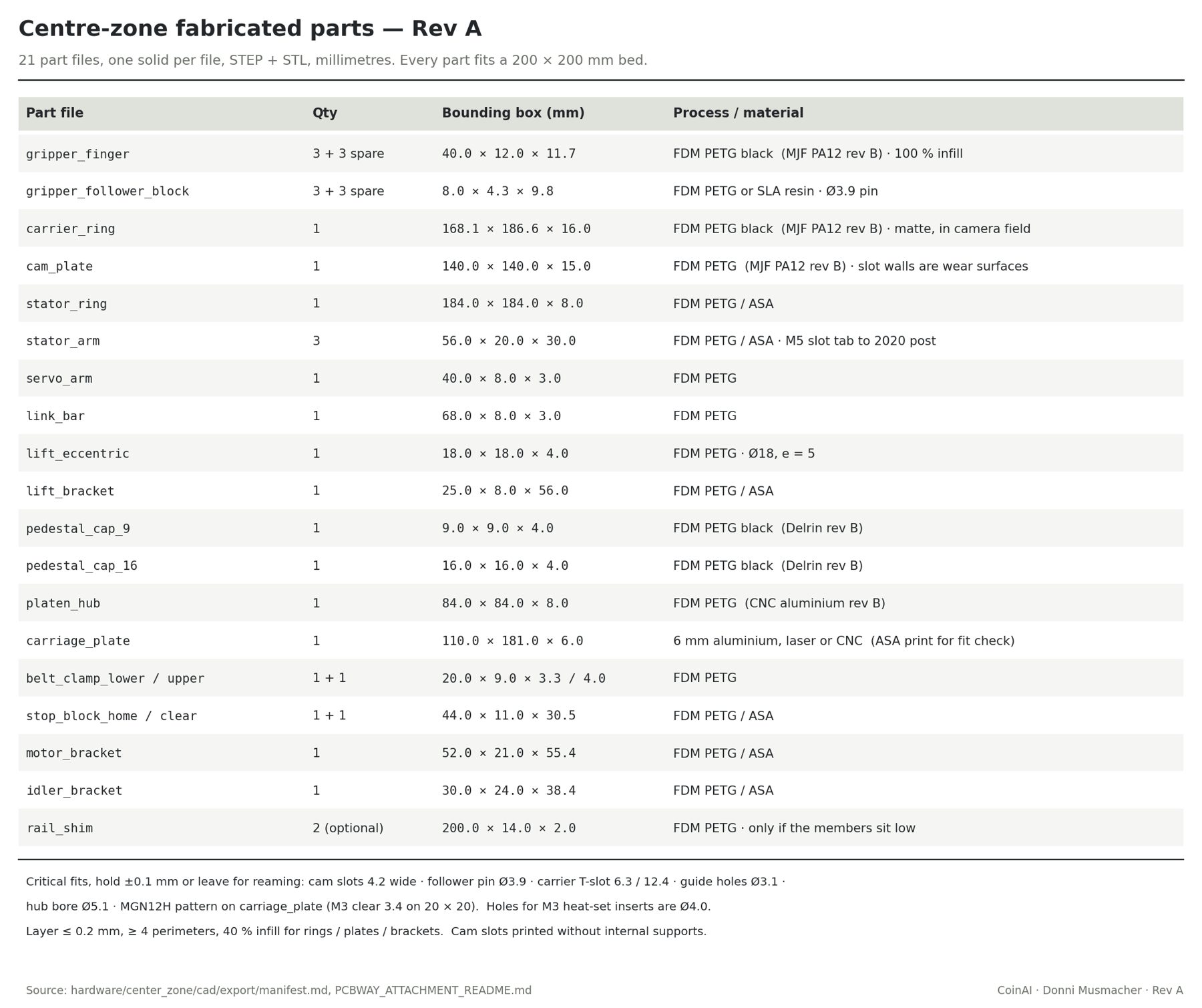
The Rev A fabricated parts list, with critical fits.
Parts inside the camera field are matte black. The cam slot walls are wear surfaces, which is why the cam plate, carrier and fingers move to MJF PA12 after the first fit check. The carriage plate is 6 mm aluminium because it carries a motor and sets the platen's height.
What is there today:
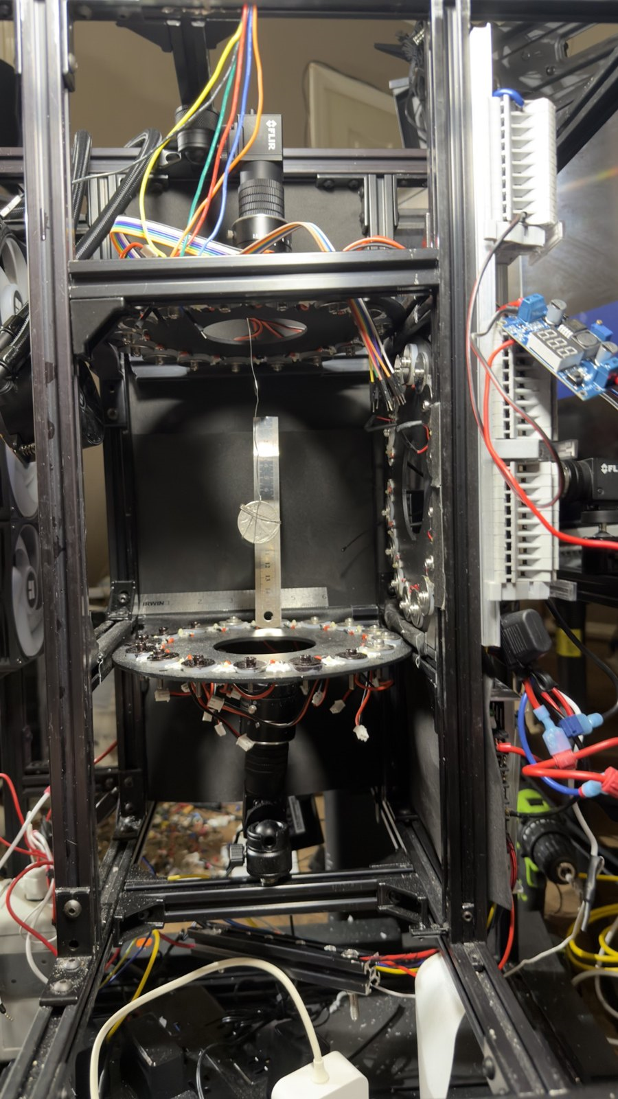
Proof that the geometry is satisfiable: a coin held at the exact centre of all three axes by a hand-bent wire cage, with a steel rule for scale.
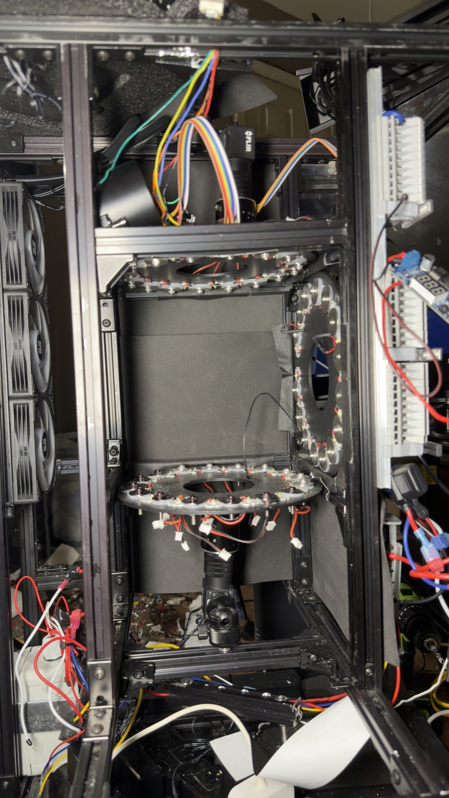
The empty centre zone between the illumination planes.
6. Bill of materials
To be fabricated (this request)
- 21 printed or machined part files, as tabulated above
- 3 x 16-channel MOSFET switching PCB
Motion hardware
- NEMA 17 stepper 42HDC0008EC (0.4 A, 0.09 N.m, 0.9 degree): 2 used, 3 on hand
- TMC2209 stepper driver: 2 used, 4 to 5 on hand
- SG90-class servo: 2 used, 2 on hand. Metal-gear spares of the same footprint to buy
- MGN12 rail 200 mm with MGN12H block: 2, to buy
- GT2 6 mm belt about 600 mm, 20-tooth pulley, idler, and a belt and clutch kit with motor attachments: on hand
- 100 mm lazy-Susan bearing: on hand
- Compression springs 4 x 10 mm: 3
- 3 mm steel pin for guides and followers
- Normally-closed end-stop micro-switches: 5 on hand. Two on the shuttle (HOME and CLEAR), the rest for the gripper and safety inputs
- Rubber grommets, washers and bushings, various: on hand. Used as the stop pads and for cable pass-throughs
- Logic level converters: on hand, between 3.3 V controllers and 5 V devices
- Carriage rollers for 2020 track: 4 on hand, spare. Rev A uses linear rails instead
Fasteners
- M3 heat-set inserts, about 24
- M3 socket-head screws in 8, 10, 12, 16 and 20 mm
- M3 grub screws x 4, M3 countersunk x 2
- M4 x 10 and M4 x 16, 4 each
- M5 x 10 with 2020 drop-in T-nuts x 12, M3 T-nuts x 16
Lighting electronics (built)
- 48 x 3 W white LED on star boards (LEDGUHON JH-3535W6P45, 6500 K, 60 degree, 2.8 to 3.0 V forward), fitted bare with no secondary optics
- 3 x illumination platen: 200 mm disc with a 70 mm bore, 3.2 mm 5052 aluminium, laser-cut, deburred, matte black powder coat
- M3 screws, nuts and 14 mm fender washers for the LED clamps
- 48 x 12 ohm 10 W cement resistor
- 48 x IRLZ44N, 48 x 220 ohm, 48 x 10 kilohm
- 3 x PCA9685 16-channel PWM board
- Spares on hand: about 20 MOSFETs, about 60 LEDs of the same colour bin, 12 ohm 10 W resistors, perfboard
Already in the machine
- 3 x Teledyne FLIR Blackfly S (2 x 20 MP GigE with PoE, 1 x 6.3 MP USB 3.0), Computar V5028-MPY 50 mm lenses
- Raspberry Pi 5 with Hailo AI HAT+ and touchscreen, Raspberry Pi Pico W
- Workstation: ASRock X870E Taichi, Ryzen 9 9900X, 2 x RTX 5060 Ti, 1000 W supply
- 2 x 350 W 12 V supplies, fused distribution, emergency stop, buck converter for 5 V
- Three temperature sensors (optical axis, coin plane, lower bay), 24 GHz radar, four-microphone array
- PoE injectors and a dedicated network switch for the two GigE cameras
- 27-inch panel salvaged from a 2012 iMac, mounted in portrait as the status display
Authentication sensing, on hand and not yet integrated
- Load cells: 100 g, 750 g and 2 x 3 kg, with HX711 24-bit converters and a calibration weight set, for weighing the coin
- A neodymium magnet with hall sensors, for magnetic response
- Time-of-flight and radar presence sensors, and a laser beam-break hand cutoff
Mass and magnetic response are intended as two checks independent of imaging. They are designed intent, not a demonstrated capability.
7. Build log
- Frame. 2020 extrusion with four contiguous centre posts, so the optical axis is set by the structure.
- Optics. Three cameras mounted on slides and ball joints on that one axis.
- Lighting, first generation. Hand-drilled bare aluminium platens and the first MOSFET boards. The boards were wired with the wrong pinout and rebuilt twice; the whole set was eventually scrapped. Section 8 has the details.
- Lighting, second generation. Machine-cut platens, precisely drilled and powder-coated matte black, and all 48 MOSFET channels rebuilt correctly as three boards, pinout verified by meter. Two planes first, then a third for the edge. Forty-eight LEDs, each with its own resistor, MOSFET and PWM channel. Driver topology confirmed on the bench in June 2026.
- Resistor bank. The 48 resistors first hung from a terminal block by their own leads. In September 2026 I rebuilt them as one module: three banks of 16 on a single board, the 12 V side bussed on the back, one harness per plane, on an aluminium plate in open air.
- Compute. The workstation built into the same frame, with the radiator mounted in the frame wall.
- Watchdog. Written and unit-tested in September 2026, after working out that the gate pulldowns do not cover a hung controller.
- Centre-zone design. Rev A CAD completed in September 2026.
- Status panel. A 27-inch panel from a 2012 iMac mounted on the front face in October 2026.
- Now. A bench measurement pass against the real machine to confirm every dimension the CAD assumed.
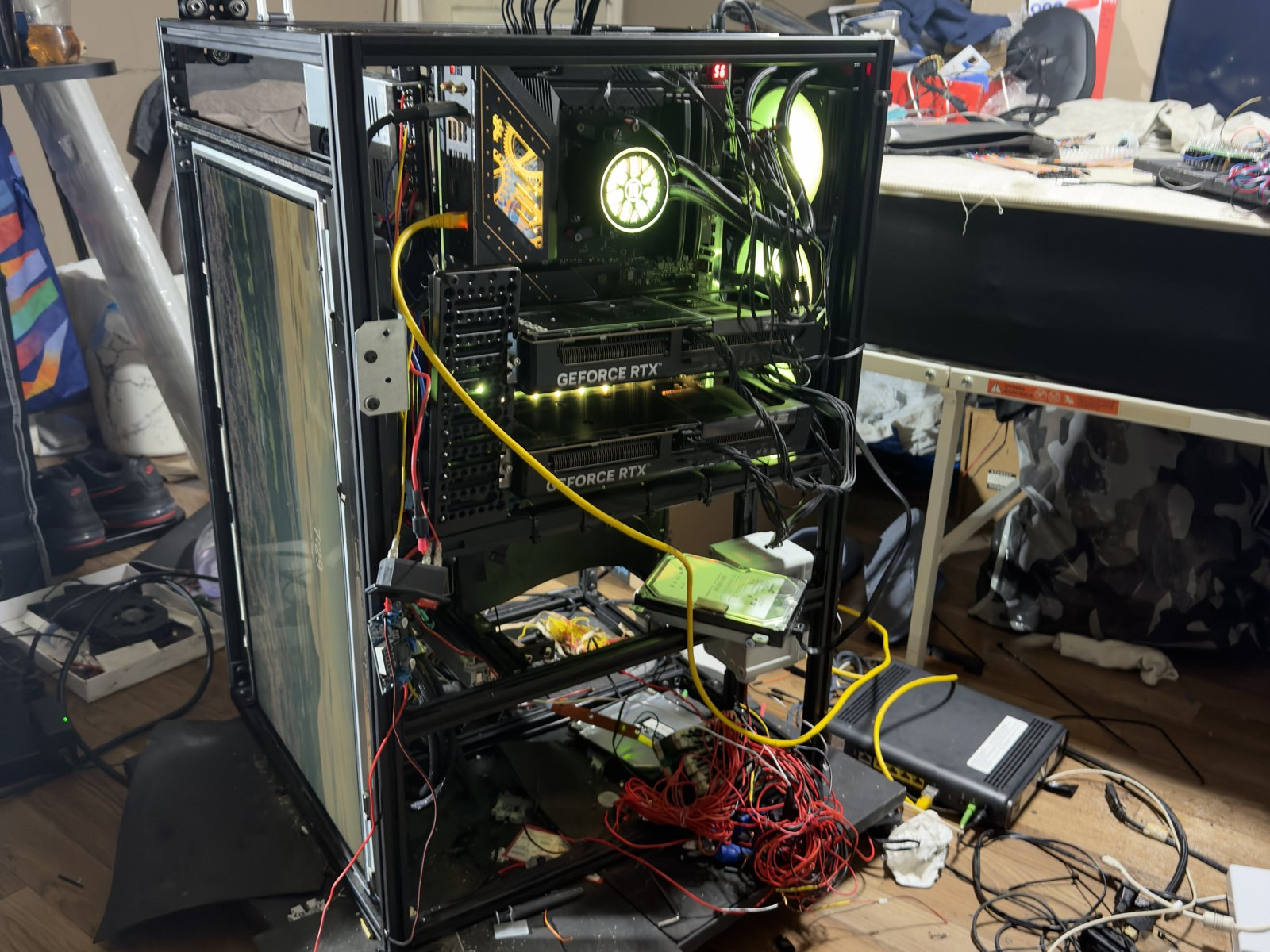
The compute bay: two GPUs and the liquid-cooled CPU inside the same frame as the optics.
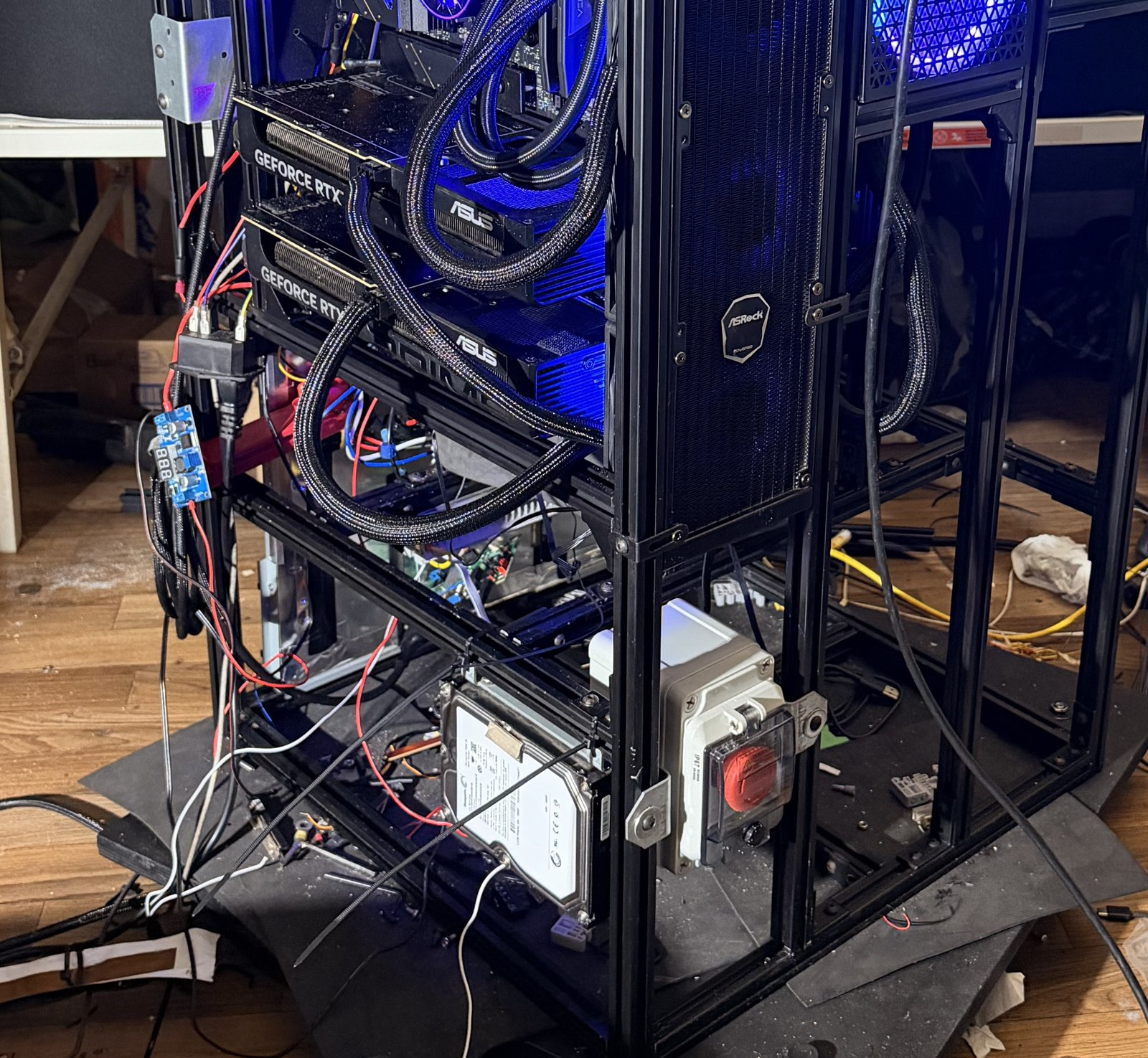
The other side: radiator and hoses, the 5 V buck converter, and the emergency-stop station at the bottom.
8. What I got wrong, and redid
I am self-taught, and there were stretches of this build where I did not fully understand what I was making. I would rather say so than present a clean story, because the work has to be falsifiable to me before it can be believable to anyone else. These are the places I was wrong, saw it, and started over.
- Forty-eight MOSFETs, wired wrong, twice. I asked an AI assistant for the MOSFET pinout and wired all 48 channels from its answer without checking it. The legs were wrong. I rebuilt, asked again, and it was wrong a second time. That is on me: I took an answer I had not verified. I scrapped the lot, bought new MOSFETs, read the datasheet myself, confirmed gate, drain and source with a meter, and built all 48 channels a third time as three separate boards. That was the point where I actually understood the circuit. Every pinout on this build is now checked with a meter before anything is soldered.
- The first platens. I hand-drilled the first 200 mm platens from bare aluminium and fully populated them. They worked, and I could see how to do it better, so I replaced them with machine-cut, powder-coated discs.
- The frame. I changed the centre structure to two vertical posts, then reversed that and went back to four, because four posts put every disc and camera on one axis by construction.
- Parts I bought and could not use. I bought secondary optics for the LEDs without realising the lens needs a separate holder to mount. They are still in a box. The LEDs run bare.
- An assumption that cost me height. I believed the LED discs and the cameras had to move together. They do not: the focus distance belongs to the lens, and the disc height is independent. That one assumption was the only thing holding the discs where they were.
- The resistors. The first version hung 48 hot resistors from a terminal block by their own leads. I rebuilt them as one bussed module on a plate in open air.
- A safety claim that was not true. The driver's own source file said the gate pulldown resistors would turn the lights off if the controller died. They would not, because the PWM chip holds its last state. The file now says so, and a watchdog covers the case.
- The first model. Run 001 failed at 0.203 composite. I traced it to an encoder too small to train from scratch, rebuilt on a DINOv2 ViT-S/14 backbone (Apache 2.0, Meta AI), and Run 002 improved on it 21.7 times. Both write-ups are kept.
- My own parts lists. More than once a list said a part was in hand when it was not. I now check the bench before I trust the list, which is why the Rev A CAD is being measured against the machine before any file is released.
Every one of these cost time or money I did not have much of. I would make the same call each time.
9. Software, stated precisely
Stage 1 coin detection runs at 97.65% accuracy on a held-out test split (97.9% precision, 97.2% recall), at 1.05 M parameters and 4.2 MB, small enough to run on the Pi 5 with the Hailo HAT+. The data is 4,192 training, 524 validation and 524 test images, first-party only, with a sha256-bound chain of custody and schema-enforced prevention of leakage between splits.
To be exact about that number: Stage 1 is locating the coin in the frame. It is not grading, not variety attribution and not counterfeit detection. Stages 2 to 10 are designed and not yet trained. One stage proven and a credible method for the rest is the honest description, and it is the one I would rather be held to.
10. What is not done
- The Rev A parts have not been fabricated or fit-checked. The bench measurement pass is in progress.
- The PCB layout is not finished. The schematic is.
- The formal 48-channel verification record is pending.
- Vision stages 2 to 10 are not trained.
- There is no automated coin handling yet. That is what this request is for.
11. The request
- A. The printed mechanical set, Rev A: the parts in the table above, in PETG, with matte black for the parts inside the camera field.
- B. The carriage plate: 6 mm aluminium, laser-cut or CNC.
- C. Three 16-channel MOSFET switching PCBs.
I have already paid for my own iterations: the platens and the driver boards are both on their second generation. PCBWay sponsors a project once, so the files will be uploaded once, when the measurements are confirmed and the layout is complete. I would rather be a week slower than send a revision.
If PCBWay fabricates these parts I will:
- publish the CAD and the PCB design files for the sponsored parts openly,
- write a full build article covering the design, the fabrication and the measured results, crediting PCBWay's fabrication,
- feature the parts in the build photography,
- and report the outcome honestly, including anything that does not work.
Words to PCBWay
Thank you for reading this far. Everything in this machine except three items is built and working, and those three are the ones I cannot make at home: a rim-only coin gripper, a platen carriage and rail, and three switching boards that today exist as hand-soldered perfboard. These parts are what stand between an instrument that can light and photograph a coin and one that can pick it up, turn it over to both cameras, and hand back a result. Contact: through my sponsorship email thread with the PCBWay marketing team.
- Comments(0)
- Likes(0)