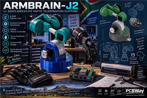
ArmBrain-J2: DIY 6-DOF Haptic Robotic Arm
PROJECT: DIY Low-Cost Haptic Teleoperation Arm - Fully Self-Built in PETG-CF | 24V System with TMC2209 + TB6600 + ESP32-S3/C3
Who I Am:
I am an independent builder from Fouriesburg in South Africa. I have no university laboratory, no team, and no funding—only my own 3D printer, soldering station, and the components that I buy for myself. I design all of the parts myself, the mechanical ones in Fusion 360 and the PCBs in EasyEDA, and I produce all the structural parts using PETG-CF since it offers strength and heat resistance. This has been the main project that I have been working on for months in my home laboratory.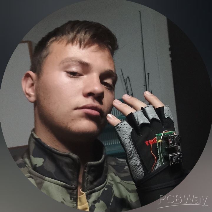
The Goal:
To construct a haptic teleoperation system that works for under $300. Since industrial arms use $800 worth of harmonic drives per joint and $2000 controllers, I am attempting to show that you can achieve 80% of the performance at just 10% of the cost by applying smart design—using 3D-printed cycloidal reducers, TMC2209s in UART mode, and ESP32s for wireless teleoperation.
Mechanical Design - All Self-Printed:
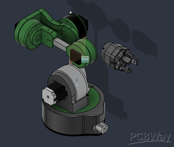
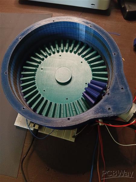
I have had the bracket, joint housing, and cycloidal reducer manufactured in PETG-CF (carbon fiber PETG). I selected PETG-CF rather than PLA since PLA creeps when exposed to motor heat and PETG-CF is considerably stiffer – as a result, the cycloidal disks no longer flex when under load. The layer height is 0.2mm with six walls and 50% gyroid infill for the load-bearing parts.
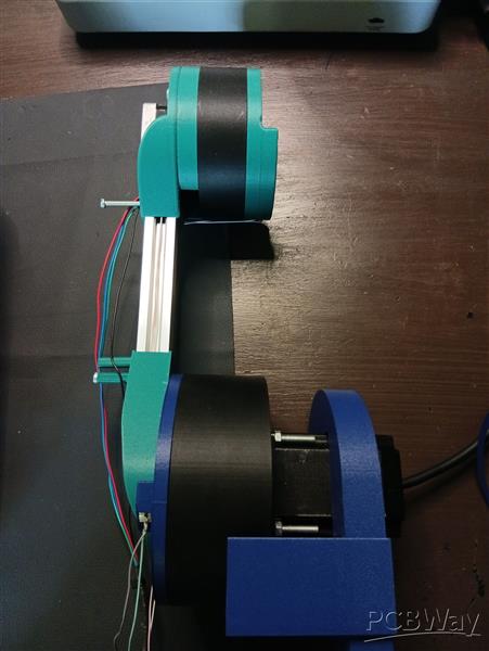
The arm currently has 5 degrees of freedom (the base rotates using a 47rpm DC motor, the shoulder hase a NEMA23 with a TB6600 and has four NEMA 17 motors for, elbow, and wrist pitch,yaw and roll. For the joints I use my own 3D printed cycloidal reducers with a ratio of about 19:1 — although not as good as harmonic drives, they have no backlash when compared to ordinary 3D printed planetaries. Later on I plan to test genuine harmonic drives once teleoperation is working, but at present the PETG-CF cycloidal reducers keep the cost at $2 pergearbox
.
Electronics - 24V Unified System & Custom EasyEDA Boards:
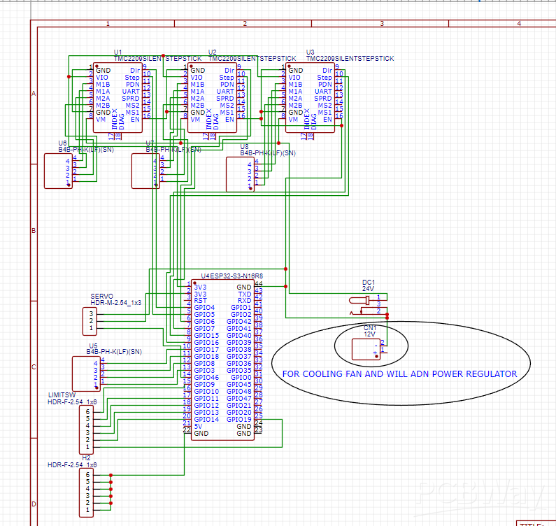
I use one single PSU of the Meanwell type rated at 24 volts to power both the NEMA 17 and NEMA 23 motors. This arrangement makes the cabling simpler and provides greater torque when operating at higher speeds than would be the case with 12 volts. Since I know that 24 volts at 4 amperes require adequate trace width, I have designed my boards using EasyEDA with that requirement in mind.
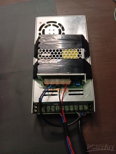
Board 1: Main Control Board (Designed in EasyEDA, 2-layer, 1oz copper, but with wide power lanes):
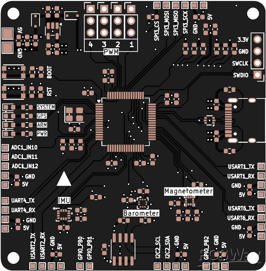
- The brain uses an ESP32-S3-WROOM-1, responsible for carrying out inverse kinematics, acting as a WiFi UDP server, and handling motion planning. The S3 model was selected because it has a dual core and sufficient RAM for the IK calculations.
- For the drivers, I'm using four TMC2209 chips in UART mode (I operate them with sensorless homing, at 800mA RMS for the NEMA 17 motors, and I use StealthChop to ensure silence). I have included sockets so that I can replace them if they blow.
- The driver uses a TB6600 header rather than an onboard TB6600 chip, the header connecting to an external TB6600 module for the NEMA 23 motor (4A, 24V). This arrangement keeps the high current separated from the main board.
- Power: 24 volts input is converted to 5 volts at 5 amperes using a buck converter and then to 3.3 volts with an LDO to supply the ESP32. I have calculated the trace width: the traces for the 24 volts are 2.5 millimetres wide to carry 4 amperes, including thermal reliefs and a solid ground plane to cope with the switching noise from the driver. Bulk capacitance of 470 microfarads is provided on the 24 volt supply close to the drivers.
- Protection: Fuse on 24V. TVS diode. Separate AGND and DGND.
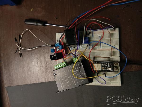
At the moment the entire setup is based on breadboard connections using pin cables and it fails every ten minutes—the wires melt, the cables come loose at 24 volts, and the TMC2209 chips overheat when there is no adequate copper pour. We really need a printed circuit board.
Board 2: Glove Board V1 (Ultra-Compact, Designed in EasyEDA):
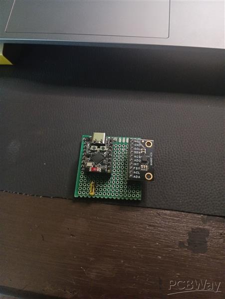
- Brain: the ESP32-C3 Mini (also known as the SuperMini) is tiny and has low power consumption, which is sufficient for reading data from an IMU together with WiFi.
- Sensor: ICM-20948 9-axis IMU breakout, used for tracking hand orientation (in terms of yaw/pitch/roll). I2C communication takes place at 400kHz and includes the appropriate pullups. The DMP is being used for the quaternion.
– The board must have dimensions of a maximum of 35 mm by 45 mm so that it will fit onto the back of the hand with the use of a velcro strap; all the components should be on the upper side and the battery connector on the lower side. There should be mounting holes for the strap.
- Present status: This is only at the orientation stage; the V2 version will include 5x flex sensors on the fingers and 2x small vibration motors to provide haptic feedback when the arm reaches a limit.
– Communications: WiFi UDP at 100Hz – C3 transmits the quaternion and battery voltage to S3. WiFi was selected over Bluetooth because of the range needed in my workshop.
System Architecture:
The glove (ESP32-C3 Mini with ICM-20948) sends data via WiFi UDP at a rate of 100Hz consisting of quaternions to the main brain (ESP32-S3), which then carries out inverse kinematics, before passing the signal on to the step generation stage, which in turn sends the signal via UART to the TMC2209 and sends STEP/DIR signals to the TB6600, thereby driving the motors of the PETG-CF arm. Later on, an ESP32-CAM will be placed on the wrist to provide vision capabilities and to enable auto-centering as well as a simple pick-and-place automation.
Software:
The ESP32-S3 handles the custom IK solver , acceleration limiting, while the ESP32-C3 is responsible for IMU fusion and low-power WiFi. All of the code, written in VScode, will be open source.
Current Status & Build Log:
- PETG-CF arm frame 100% printed and assembled
- 2x TMC2209 + 1x TB6600 + NEMA 17/23 wired and tested individually at 24V
- ESP32-S3 + ESP32-C3 talking over WiFi UDP (tested)
- ICM-20948 reading stable quaternions
- Breadboard version moves but unreliable - need PCBs to proceed to full teleop test
- EasyEDA schematics and PCB layouts 100% done, DRC passed, with correct 24V trace widths
Why I Need PCBWay Sponsorship:
I actually have all the components—a 24V /12v power supply, all the steppers, all the drivers, both ESP32s, and PETG-CF filament—I produce everything myself. The one thing I can't manage to make at home is a proper printed circuit board with the correct power lines for 24V high current; breadboarding the 24V stepper drivers is unsafe and my pin connectors keep melting or failing. Thanks to PCBWay's sponsorship I can now have these two boards properly manufactured and carry out smooth teleoperation testing.
It's not a school project; it's an independent project that I have financed using money earned from my side jobs. Once version V1 is working, I will make available all the EasyEDA files, the STLs (with a PETG-CF profile), and the code so that other builders in Africa will be able to replicate a low-cost teleop.
Apply for sponsorship >>
- Comments(0)
- Likes(0)