


|
KiCad 9.0 |
LED Ring Clock
LED Ring Clock
Display Overview
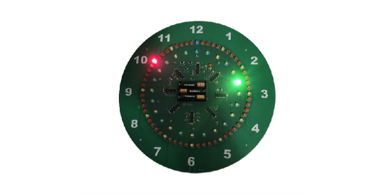
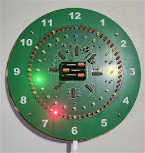
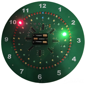
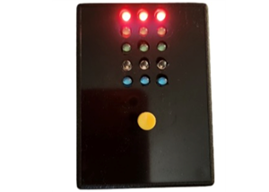
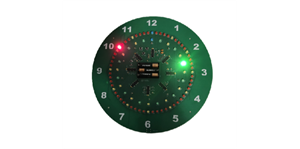
- The inner LED ring shows the hour: yellow on the hour and green on the half hour. At 12:00, the indicator is blue.
- The outer LED ring shows the minutes in red. Every fifth LED is yellow, except at 12:00, where the indicator is blue.
- This clock does not display seconds.
Setting the Clock
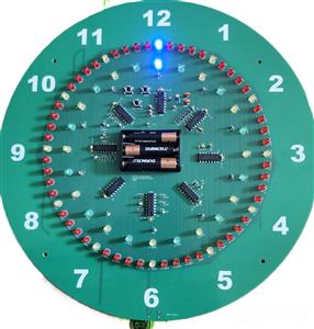
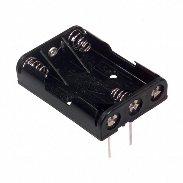
Install three AAA batteries first. When the clock is powered on for the first time, it starts at 12:00. Set the time by advancing the display as you would with a mechanical clock.
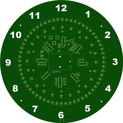
There are three push buttons located between the hour LEDs near the 11 and 12 positions:
- SW1 – Minutes: Advances the minutes one step at a time. The hour indicator and half-hour position advance normally as the minutes progress.
- SW2 – Hours: Quickly advances the display so you can set the hour.
- SW3 – Zero Minutes: Resets the minute counter to synchronize the clock more precisely. You will not see any visible change when you press it.
Time.gov is a reliable source for accurate time information. For example, to set the clock to 3:15, start with fresh batteries so the clock begins at 12:00. Hold the Hours button until the display is close to 3:00. Then use the Minutes button to advance to one minute past the current time, and press Zero Minutes to reset the minute counter. When your time source reaches exactly 3:15:00, press Zero Minutes again to synchronize the clock. Using the Zero Minutes button is optional, but it improves accuracy.
Power
- A USB-C connector is located at the 6 o’clock position for external power.
- Use a USB-A to USB-C cable with a 5-volt USB charger that has a USB-A connector.
- The clock will not work with a USB-C fast charger.
- The three AAA batteries provide backup power. Use alkaline batteries to prevent the clock from losing time when it is unplugged.
Notes
- I installed new batteries in the clock on Wednesday, June 9, at about 1:00 p.m. I plan to run the clock on battery power only until the batteries are depleted and then report how long they lasted. Update on June 21st the LEDs were on but the clock had stopped just after 1:00 pm, 13 days on 3 AAA batteries.
- I ordered five circuit boards from PCBWay, with one board assembled. The time from ordeing to delivery by DHL was one month.
- You can order the clock from PCBWay as either bare boards or a fully assembled unit, and the Gerber files are also available. I used red, green, yellow, and blue LEDs in my design, but you can choose any colors you prefer. If you want PCBWay to assemble the clock with different LED colors, you will need to update the bill of materials. If you like the clock and want to improve the design, download Other Files For Assembly Clock.zip. It includes all KiCad 10.0 project files. The ZIP file also contains ClockTemplate.pdf; print it at actual size to make a template for the four mounting holes located between 10 and 11, 1 and 2, 4 and 5, and 7 and 8.
- All parts should be available on DigiKey or Mouser. Except for the battery holder and USB connector Amazon is also a good option.
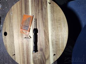
- Whether you order the clock fully assembled or build it yourself, you’ll need to mount it. Round boards from stores like Hobby Lobby or Michaels work well; I used a Round Acacia Wood Cutting Board from Woodpile Fun! at Hobby Lobby. For mounting, I used M3 12 mm standoffs, M3 20 mm screws, and M3 nuts, all listed in the component list. I drilled the holes using a small hand drill set from Hobby Lobby and an unused PC board as a template, then finished them with a Dremel. I also added round felt pads over the standoff screws to protect the wall. These are just suggestions, so feel free to use your own mounting ideas.
LED Ring Clock
Project images are for reference only. Actual production is based on the manufacturing files on the project page.
Please review the designer's notes (e.g., PCB thickness) and select the appropriate options.
PCBWay is not responsible
for issues caused by unsuitable parameter selections.
For more important ordering information, please refer to
Read More


Raspberry Pi 5 7 Inch Touch Screen IPS 1024x600 HD LCD HDMI-compatible Display for RPI 4B 3B+ OPI 5 AIDA64 PC Secondary Screen(Without Speaker)
BUY NOW


- Comments(8)
- Likes(2)
- 1 USER VOTES
- YOUR VOTE 0.00 0.00

-
9design
-
10usability
-
10creativity
-
10content
More by William Harter
-
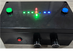
 Slot Machine
This slot machine project uses 15 colored LEDs for three reels, operated by a single push-button tha...
Slot Machine
This slot machine project uses 15 colored LEDs for three reels, operated by a single push-button tha...
-
 Reaction Game
This game utilizes two tricolor LEDs. One LED randomly lights up in blue, green, or red. The second ...
Reaction Game
This game utilizes two tricolor LEDs. One LED randomly lights up in blue, green, or red. The second ...
-
 LED Ring Clock
Display OverviewThe inner LED ring shows the hour: yellow on the hour and green on the...
LED Ring Clock
LED Ring ClockDisplay OverviewThe inner LED ring shows the hour: yellow on the hour and green on the...
-
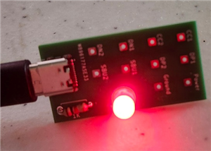 Test USB C board
I needed to add a USB C connector as the power input for one of my current projects. This board was ...
Test USB C board
I needed to add a USB C connector as the power input for one of my current projects. This board was ...
-
 Pumpkin / Jack o'lantern light
This light for a pumpkin or Jack o'lantern operates on a single 9-volt battery and cycles through fi...
Pumpkin / Jack o'lantern light
This light for a pumpkin or Jack o'lantern operates on a single 9-volt battery and cycles through fi...
-
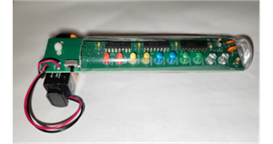
 Note Sequencer
This project utilizes two low power 555 timers (TS555CN) and a 4017 counter to produce...
Note Sequencer
Note SequencerThis project utilizes two low power 555 timers (TS555CN) and a 4017 counter to produce...
-
Programmable Mist Maker - XIAO / QT PY Extension
1062 2 1 -
RadioHAT - Raspberry Pi radio development platform
874 0 2 -
-
-
-
-
ARPS-2 – Arduino-Compatible Robot Project Shield for Arduino UNO
3327 0 6 -
A Compact Charging Breakout Board For Waveshare ESP32-C3
3934 3 8 -
AI-driven LoRa & LLM-enabled Kiosk & Food Delivery System
4323 2 2


