


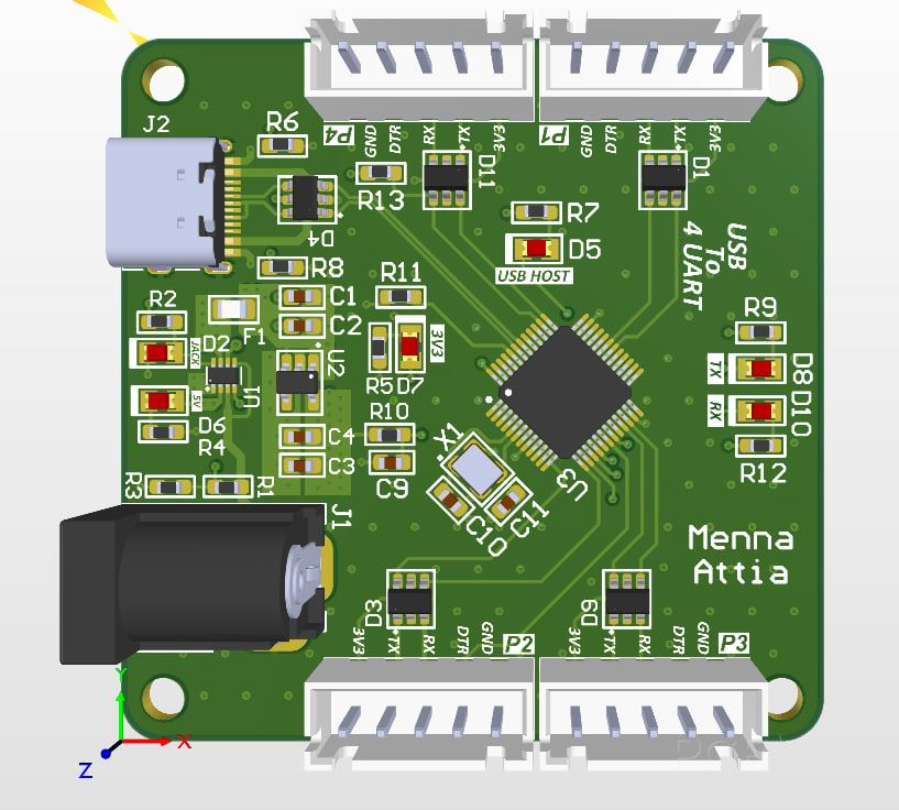
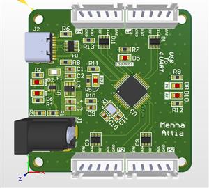
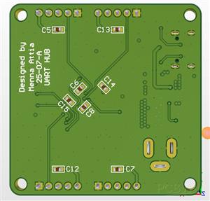
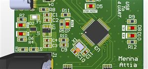
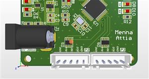
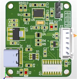
USB To 4 UART HUB
This schematic outlines a USB to 4-port UART Bridge circuit. Its primary function is to take a single USB-C connection and split it into four independent serial communication channels (UART), which is incredibly useful for debugging multiple microcontrollers or serial devices simultaneously from one computer.
Here is a detailed breakdown of the functional blocks:
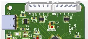
1. The Brain: USB to Quad UART Bridge
The heart of the board is the CH344Q integrated circuit.
Function: This chip acts as a high-speed USB device controller that translates USB data into four separate pairs of Transmit (TX) and Receive (RX) signals.
Peripherals: It is supported by an external Crystal oscillator circuit (typically 12MHz or 480MHz depending on design requirements) and a Reset circuit to ensure the chip starts up correctly.
ESD Protection: Notice the TPUSBLC6-2SC6 chips (D4, D1, D3, D9, D11). These are ESD protection diodes placed on the USB and UART lines to prevent static electricity from frying the sensitive silicon.
2. Power Management System
The board handles two different voltage levels: 5V (from USB or external jack) and 3.3V (for the logic).
Power Switch (TPS2116): This is an automatic power multiplexer. It intelligently switches between the USB +5V and an external Power Jack. If both are plugged in, it prioritizes one (likely the jack) to ensure the board stays powered.
5V to 3V3 Regulator (TLV75533): This is a Low Dropout (LDO) regulator. It takes the 5V rail and steps it down to a stable 3.3V to power the CH344Q and the indicator LEDs. It includes decoupling capacitors ($C1$ through $C4$) to filter out electrical noise.
3. Connectivity and Output
USB-C Input: The board uses a modern USB-C connector. It includes $5.1k\Omega$ pull-down resistors ($R8, R6$) on the CC lines, which tells a USB-C power source to provide 5V.
UART Ports (P1–P4): These are the output headers. Each header provides:
TX/RX: The main data lines.
DTR: A flow control signal often used to auto-reset Arduinos during programming.
VCC/GND: To power the connected target device.
4. Visual Indicators
The "Indicators" section provides immediate feedback on what the board is doing:
Power LEDs: Separate LEDs for 5V and 3.3V status.
Activity LEDs: An "ACT" LED shows overall USB communication.
Data LEDs: Dedicated "TX" and "RX" LEDs that flicker when data is being moved across the bridge.
USB To 4 UART HUB
*PCBWay community is a sharing platform. We are not responsible for any design issues and parameter issues (board thickness, surface finish, etc.) you choose.

- ✖ | No sharing or redistributing in any way of the 3D files or derivatives
- ✖ | No remixing
- ✖ | Non-commercial Use (only for personal use)


Raspberry Pi 5 7 Inch Touch Screen IPS 1024x600 HD LCD HDMI-compatible Display for RPI 4B 3B+ OPI 5 AIDA64 PC Secondary Screen(Without Speaker)
BUY NOW

- Comments(0)
- Likes(1)
 More by Engineer
-
Programmable Mist Maker - XIAO / QT PY Extension
777 1 0 -
RadioHAT - Raspberry Pi radio development platform
622 0 1 -
-
-
-
-
ARPS-2 – Arduino-Compatible Robot Project Shield for Arduino UNO
3096 0 6 -
A Compact Charging Breakout Board For Waveshare ESP32-C3
3713 3 8 -
AI-driven LoRa & LLM-enabled Kiosk & Food Delivery System
4025 2 2


