


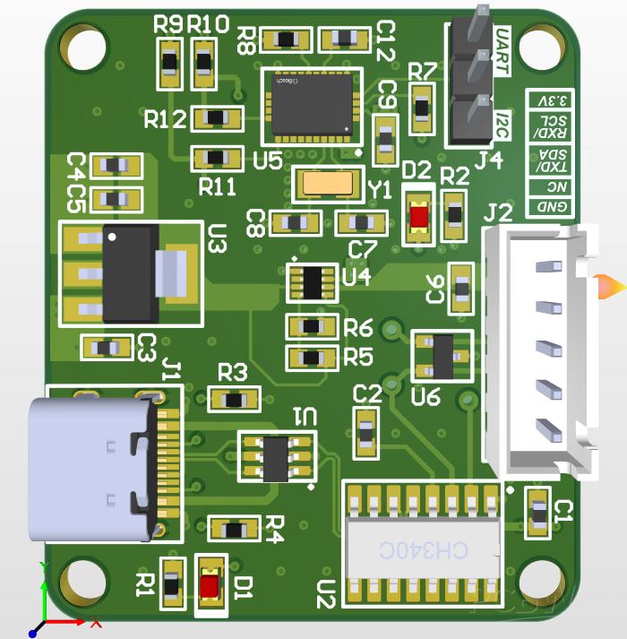
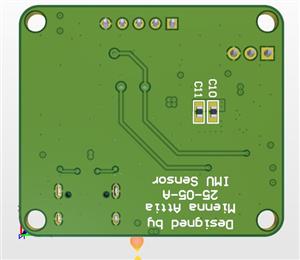
IMU Sensor Board
IMU Sensor Board designed to bridge an Inertial Measurement Unit (IMU) with a computer or external controller via USB or a JST connector. It features robust power management and signal protection.
1. The Sensor: BNO055 IMU
The core of the board is the BNO055, a high-performance Intelligent 9-axis Absolute Orientation Sensor.
Capabilities: It integrates an accelerometer, gyroscope, and magnetometer with an on-board processor to handle sensor fusion.
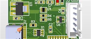
Configuration: The board includes a selector labeled "UART or I2c" (J4), allowing the user to choose the communication protocol for the sensor.
Timing: A $32.768\text{kHz}$ Crystal oscillator (Y1) provides the precise clock signal required for the IMU's internal operations.
Filtering: The "Input Voltage for IMU Sensor" section shows several decoupling capacitors ($C9, C10, C11$) used to stabilize the power delivery to the sensor's VDD and VDDIO pins.
2. Communication and Interface
The board provides two primary ways to interact with the IMU:
USB Type C (J1): This serves as the modern interface for power and data.
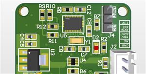
USB-UART Converter (CH340C): This chip (U2) converts the USB signals into serial UART signals that the IMU or a microcontroller can understand.
5 PINS JST (J2): An alternative connector (XH-5A) is provided for external serial connections, labeled with RXD, TXD, and power pins.
Signal Protection: * Unidirectional Protection (U1): Protects the USB data lines from static discharge.
Bidirectional Protection (U6): A PSM712-ES diode array protects the TXD and RXD lines from voltage spikes.
3. Power Management System
This board features a sophisticated "Switch Over" power architecture to ensure it can run from multiple sources.
LDO 5V to 3.3V (U3): An LD1117S33CTR voltage regulator takes the 5V from the USB (VBUS) and converts it to a stable +3V3(1) rail.
Switch Over (TPS2116DRLR): This power multiplexer (U4) automatically selects between the 3.3V generated from the USB (+3V3(1)) and the 3.3V provided by the JST connector (+3V3(2)). It outputs a unified +3V3 rail to power the rest of the board.
Indicators: Two LEDs (D1 and D2) provide visual confirmation that the VBUS (5V) and +3V3 power rails are active.
4. Physical and Utility Components
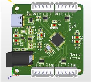
MH (Mounting Holes): Four mounting holes (H1–H4) are included for securing the PCB into an enclosure or onto a frame.
Pull-up Resistors: The $I^{2}C$ lines utilize $5.1k\Omega$ resistors ($R9, R10$) to ensure reliable data communication when that mode is selected.
IMU Sensor Board
*PCBWay community is a sharing platform. We are not responsible for any design issues and parameter issues (board thickness, surface finish, etc.) you choose.


Raspberry Pi 5 7 Inch Touch Screen IPS 1024x600 HD LCD HDMI-compatible Display for RPI 4B 3B+ OPI 5 AIDA64 PC Secondary Screen(Without Speaker)
BUY NOW

- Comments(0)
- Likes(1)
 More by Engineer
-
Programmable Mist Maker - XIAO / QT PY Extension
777 1 0 -
RadioHAT - Raspberry Pi radio development platform
622 0 1 -
-
-
-
-
ARPS-2 – Arduino-Compatible Robot Project Shield for Arduino UNO
3096 0 6 -
A Compact Charging Breakout Board For Waveshare ESP32-C3
3714 3 8 -
AI-driven LoRa & LLM-enabled Kiosk & Food Delivery System
4027 2 2


