


TempGun Pro
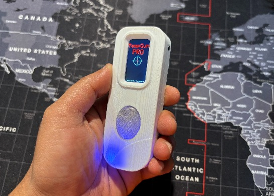
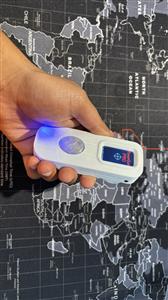
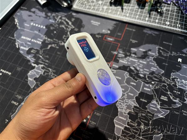
Greetings, everyone, and welcome back. Meet TempGun Pro, a handheld open-source infrared temperature capture gun powered by ESP32 C6 1.47 display, and a custom circuit.

The aim behind this project was straightforward. I needed a temperature meter to measure different things while working with electronics and 3D printing. I already had a Fluke temperature gun, but when it stopped working, I needed an urgent alternative, something cheaper that could still perform almost as well.
The best part was how easy it was to build. I reused my earlier Medic Mini project, an ESP32‑C6 dev board with a screen, buttons, and battery circuit. I just added an MLX90614 infrared temperature sensor to the GPIO pins, wrote up a quick code, made an enclosure, and the project was ready.
This article walks you through the process in a few easy steps.
Materials Required
These were the materials used in this project:
- Medic Mini Custom PCB (provided by PCBWAY)
- Waveshare ESP32-C6 1.47-Inch LCD Dev Module
- MLX90614 Infrared Temperature Sensor
- IP5306
- 10 uF Capacitors
- Push Buttons 4x4 Size
- Push Buttons 6x6 Size
- Connecting wires
- 3D-Printed Parts
- 1uH SMD Inductor
- 10K Resistors
- 3.7V 600mAh LiPo Cell
- M2 Screws
Medic Mini Mainboard
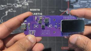
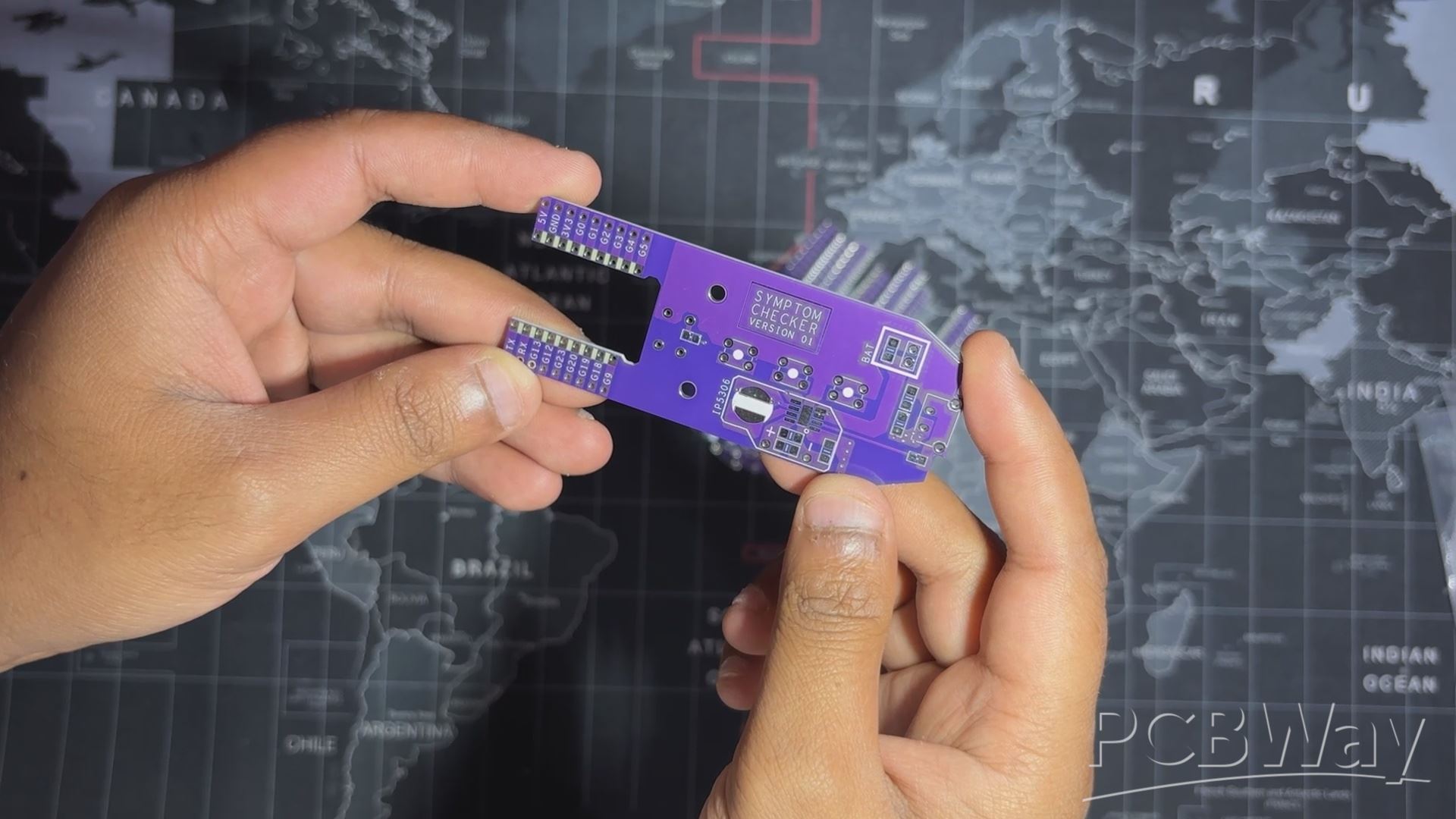
We built TempGun Pro by reusing the Medic Mini main board with just a few small modifications and add‑ons. To recap, Medic Mini was a handheld self‑diagnostic tool powered by an ESP32‑C6 and a 1.47" Waveshare display, all packed into a custom PCB and 3D‑printed enclosure. It featured three tactile buttons to guide users through symptom checks and offered quick suggestions without needing apps or internet.
The interface was straightforward: one symptom at a time, answered with Yes, No, or Not Sure. Based on those inputs, the device provided a basic diagnostic suggestion, making health checks fast and accessible.
I designed Medic Mini as a compact, standalone tool that is easy to use and built entirely from scratch, combining hardware, logic, and design into one project.
You can check out more about Medic Mini from its article page.
https://www.hackster.io/Arnov_Sharma_makes/medic-mini-f0895d#toc-materials-required-0
MLX90614
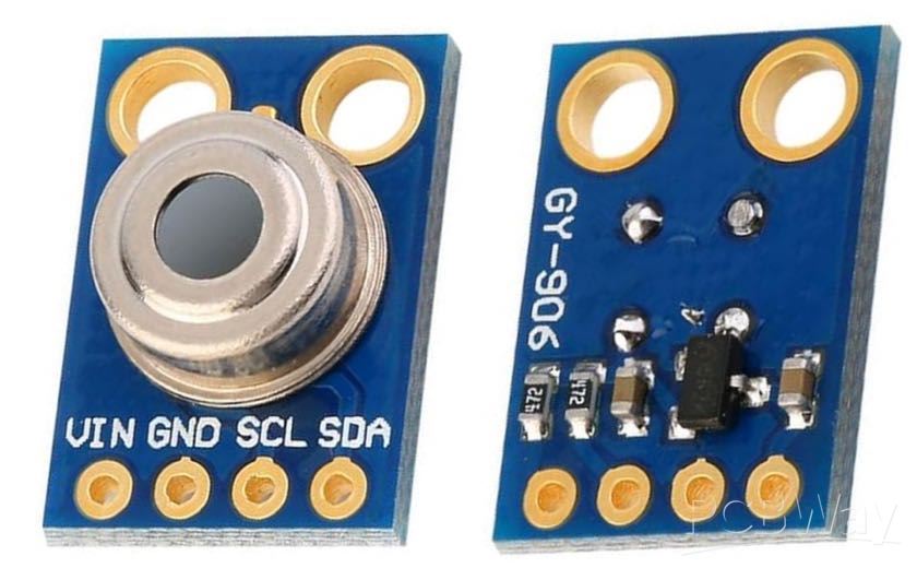

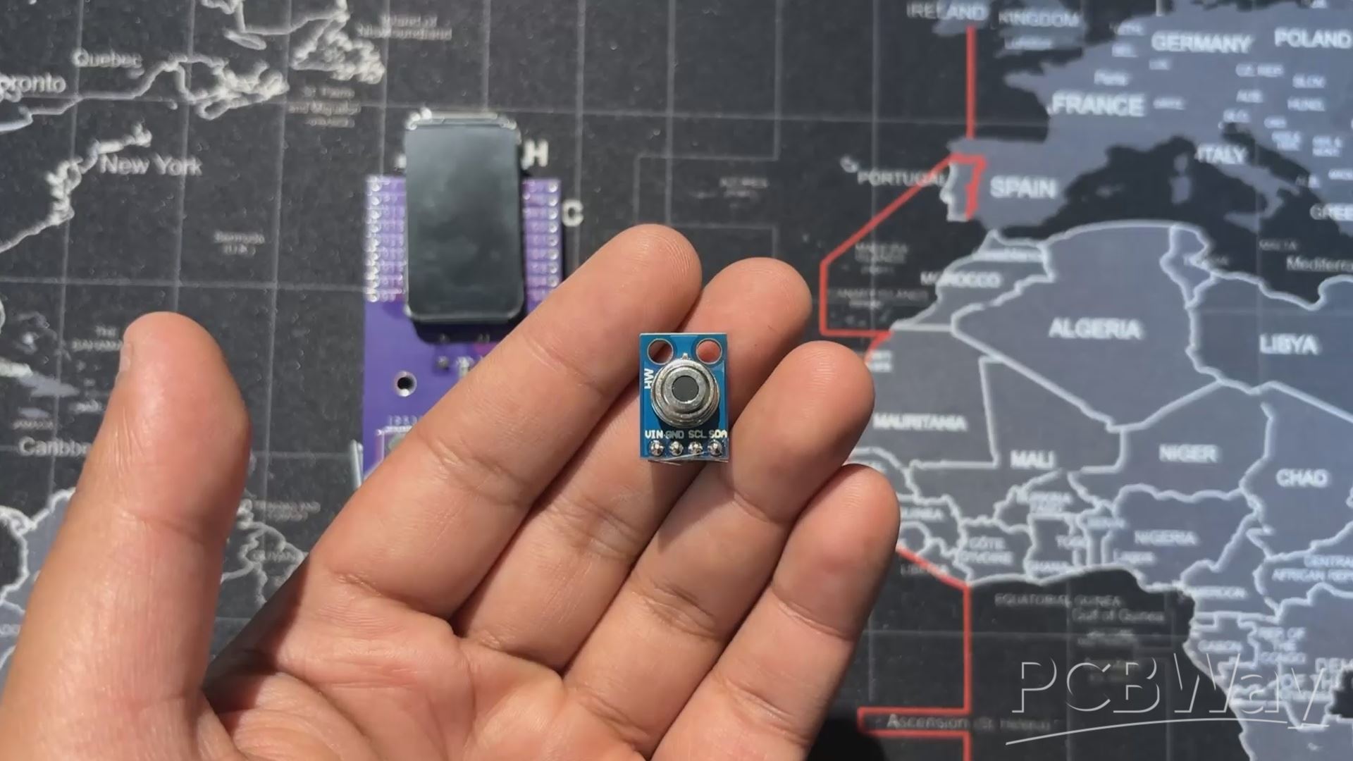
The MLX90614 is a digital infrared thermometer sensor developed by Melexis. Unlike traditional sensors that require physical contact, it detects infrared radiation emitted by objects and converts it into temperature readings. This makes it ideal for applications like handheld thermometers, industrial monitoring, and even medical devices.
It's a 3.3V device and uses I2C for communication.
The MLX90614 uses the principle of black‑body radiation. Every object emits infrared energy proportional to its temperature. The sensor’s thermopile detector captures this radiation, and an internal signal processor converts it into a digital temperature value.
You can check out the MLX90614 from below link
PCB Design
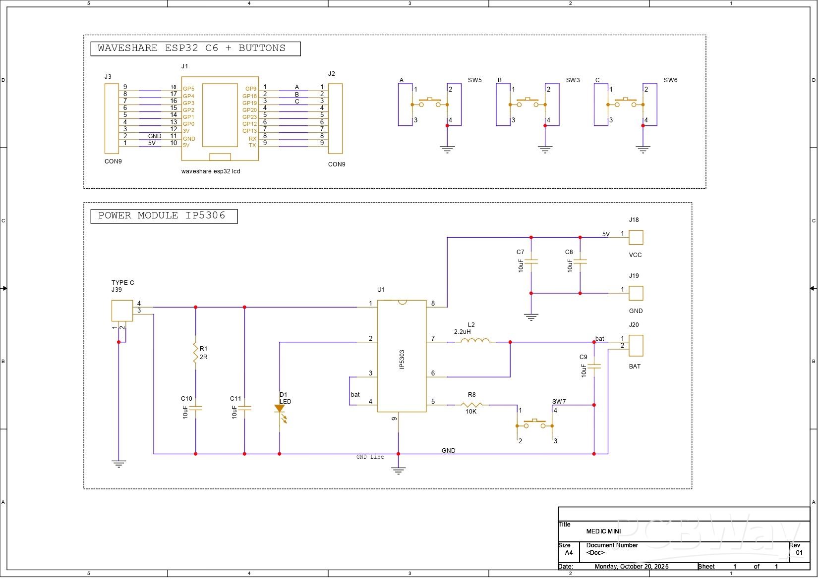
This is a schematic of the Medic Mini PCB design, which is split into two main sections. First, we built the schematic around the Waveshare ESP32-C6 Dev Board, which connects to three tactile buttons for user input. These buttons are wired to GPIO9, GPIO18, and GPIO19, with each switch also tied to GND. When a button is pressed, the corresponding GPIO pin is pulled low, registering a valid input. We will be later using GPIO18 as a temperature reading button! and will be using GPIO4 and GPIO5 as I2C pins.
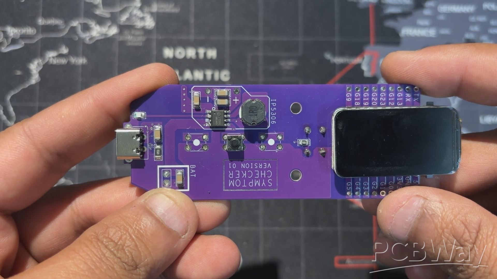
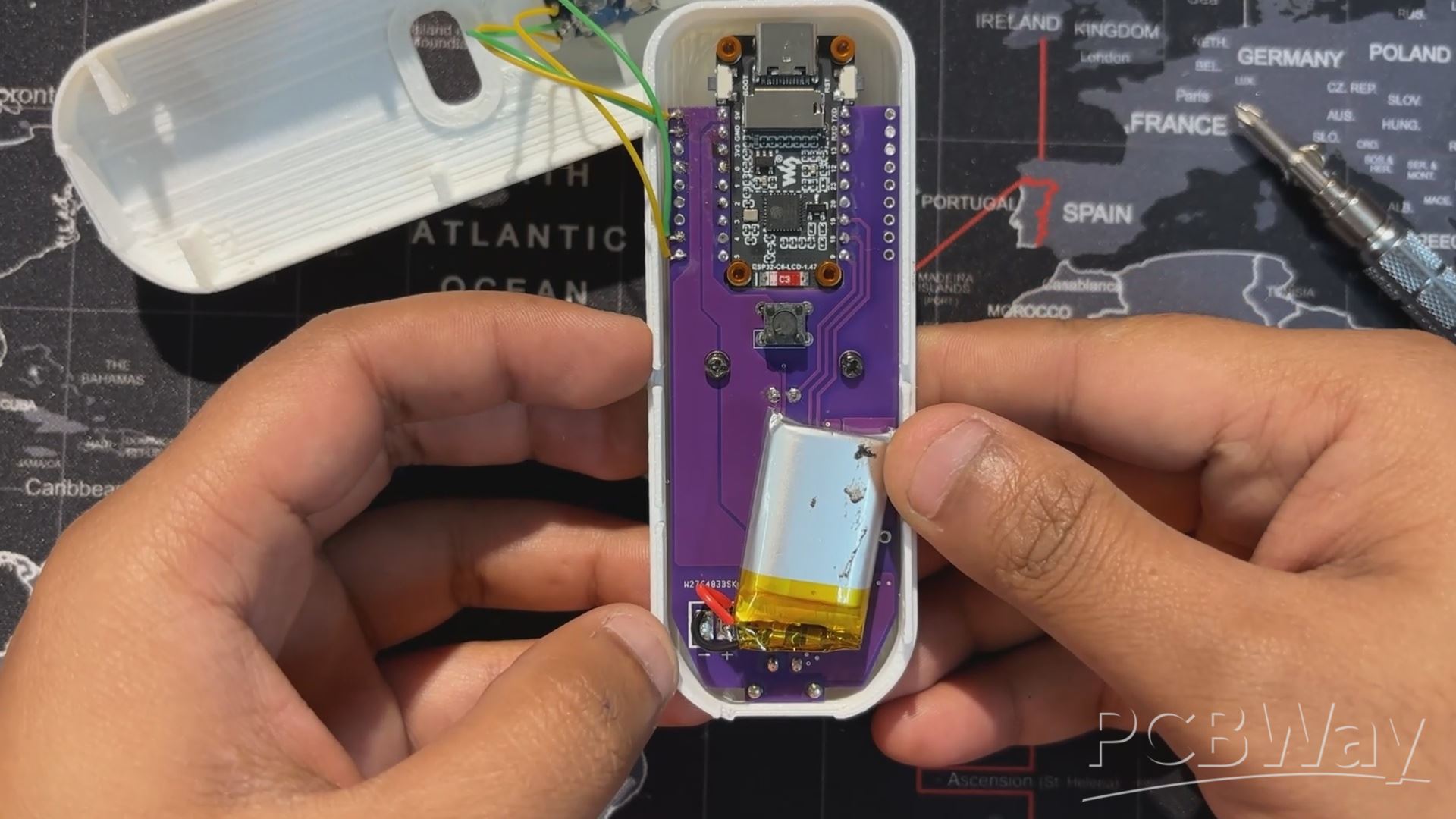
The second section handles power delivery. We use the IP5306 power management IC, which boosts the 3.7V from a lithium-ion cell to a stable 5V at 2A, enough to reliably power the ESP32 board and display. The module also includes a charging status LED; it blinks while charging and stays solid once the battery is full. Built-in features like overcharge protection, low battery cutoff, and full charge cutoff help extend battery life and prevent damage from unsafe voltage levels.
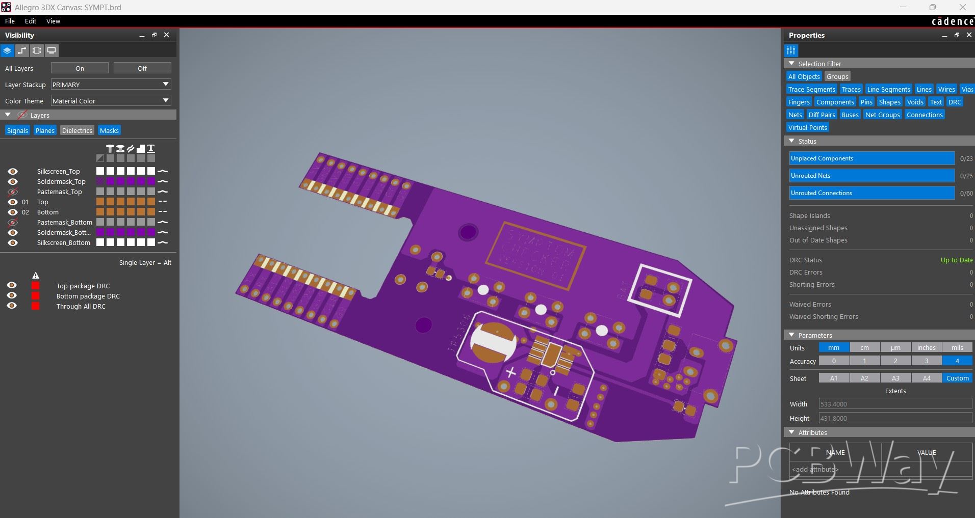
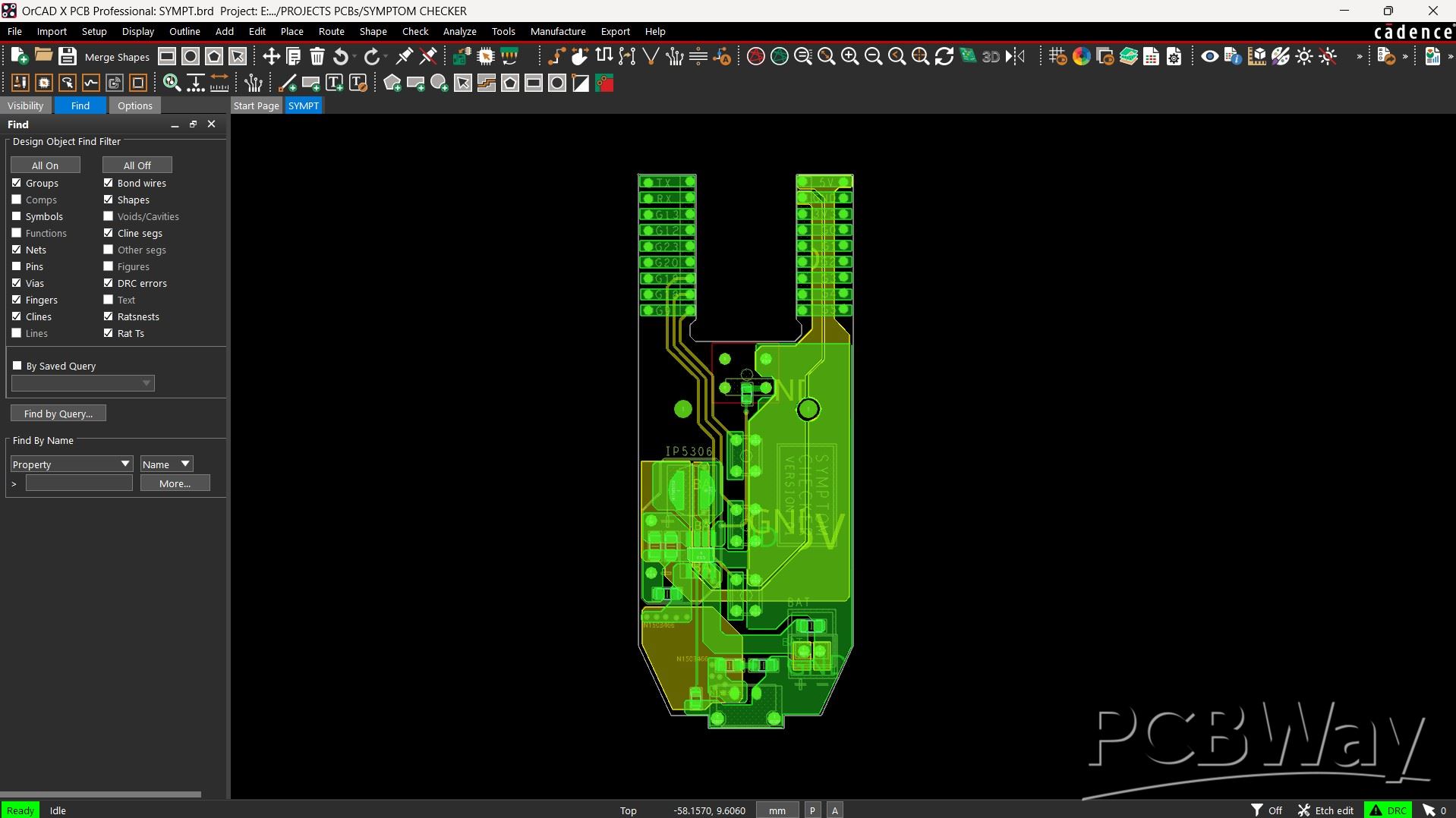
Using the dimensions from the CAD model, we prepared the PCB outline and then placed the buttons in their mounting positions as specified in the design. We did the same for the Waveshare ESP32 board, the Type-C port, and the mounting holes. The rest of the components were placed wherever we found adequate space, and then we connected the tracks and finalized the board.
After completing the PCB design, we exported the Gerber data and shared it with a PCB manufacturer to get samples made.
PCBWAY
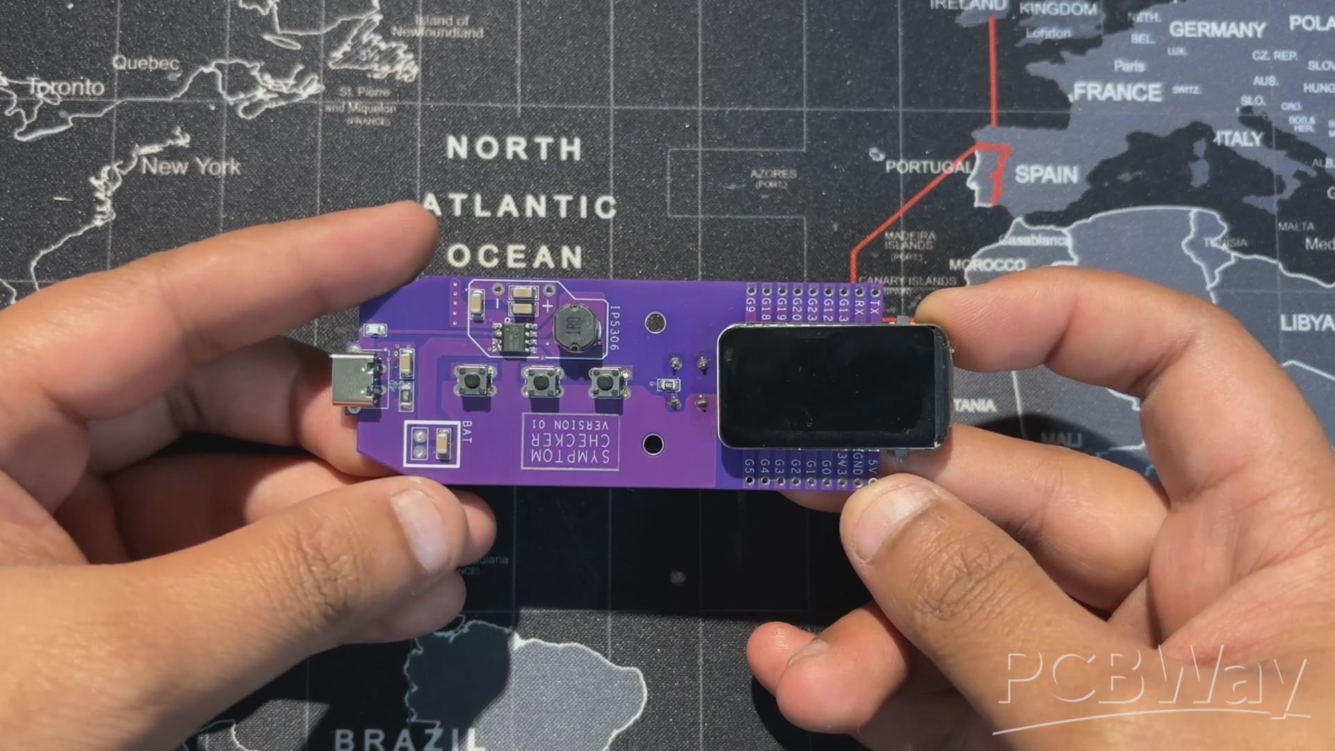
Once the board design was finalized, I opted for a purple solder mask with white silkscreen and uploaded the Gerber files to PCBWay’s quote page for fabrication.
While I typically go with a white or black solder mask for most of my builds, this time I decided to try out PCBWay’s Purple option just for a change. The order was placed smoothly, and the PCBs arrived within a week.
The quality was excellent—clean finish, sharp silkscreen, and everything matched the design perfectly.
Over the past ten years, PCBWay has distinguished themselves by providing outstanding PCB manufacturing and assembly services, becoming a trusted partner for countless engineers and designers worldwide.
Also, PCBWay is organizing the PCBWay 8th Project Design Contest, a global event that invites makers, engineers, and innovators to showcase their most creative builds. With categories in Electronics, Mechanical, and AIoT, it’s a great opportunity to share your work, connect with the community, and compete for exciting prizes.
You guys can check out PCBWAY if you want great PCB service at an affordable rate.
Medic Mini PCB Edit

- For this build, we reused the Medic Mini circuit but modified the button layout.
- The tactile push buttons connected to GPIO9 and GPIO19 were removed, since they weren’t needed.
- The center button, wired to GPIO18, was kept and repurposed as the temperature trigger button.
TEMPERATURE SENSOR WIRING
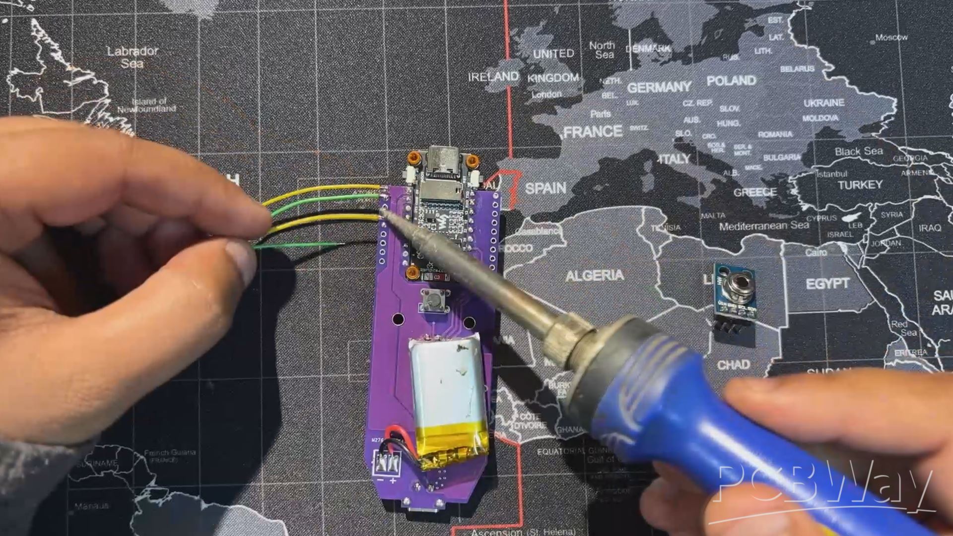
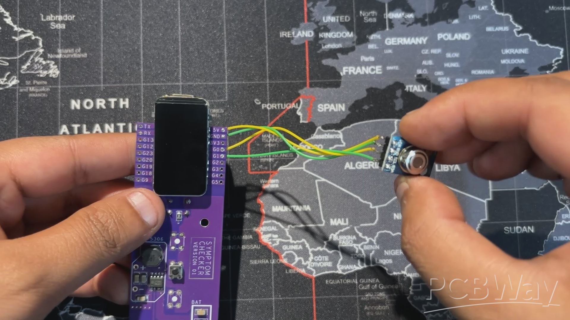
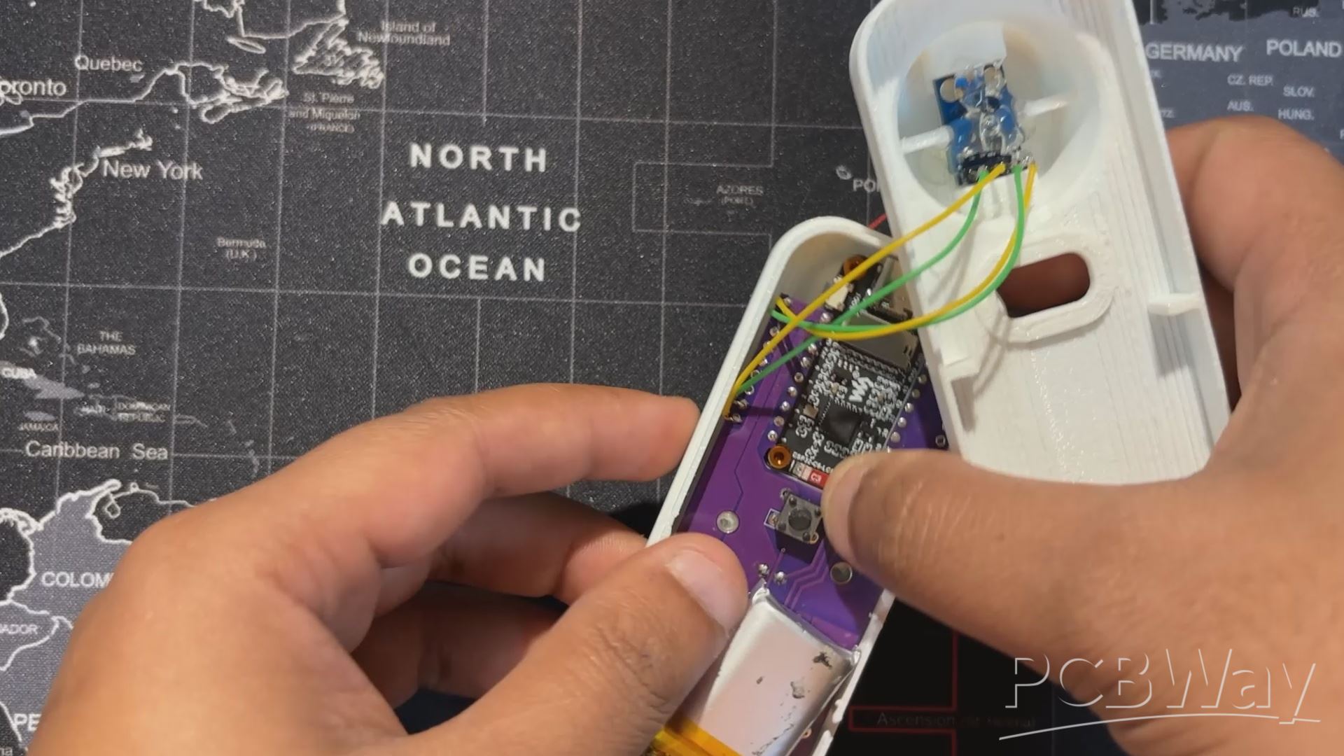
For wiring, we use four connecting wires.
- GPIO4 and GPIO5 of the ESP32‑C6 (SDA and SCL) are linked to the I2C pins of the MLX90614 sensor.
- VCC is connected to the 3.3V pin, and GND goes to ground.
This completes the basic four‑wire setup needed to power the sensor and enable communication with the Medic Mini board.
Enclosure Design
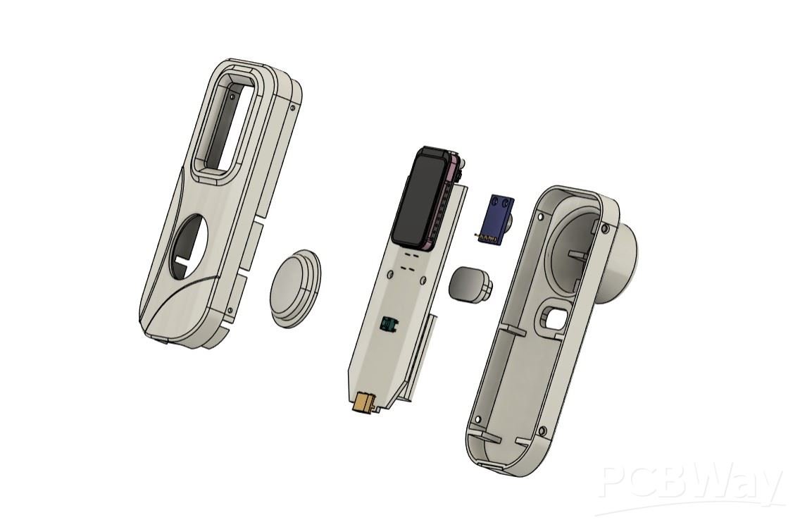
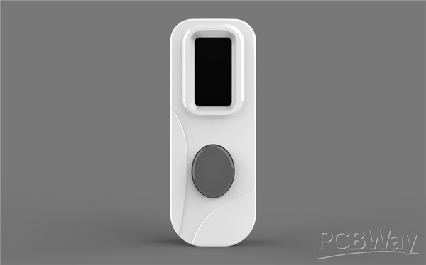

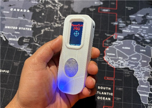
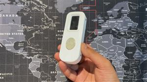
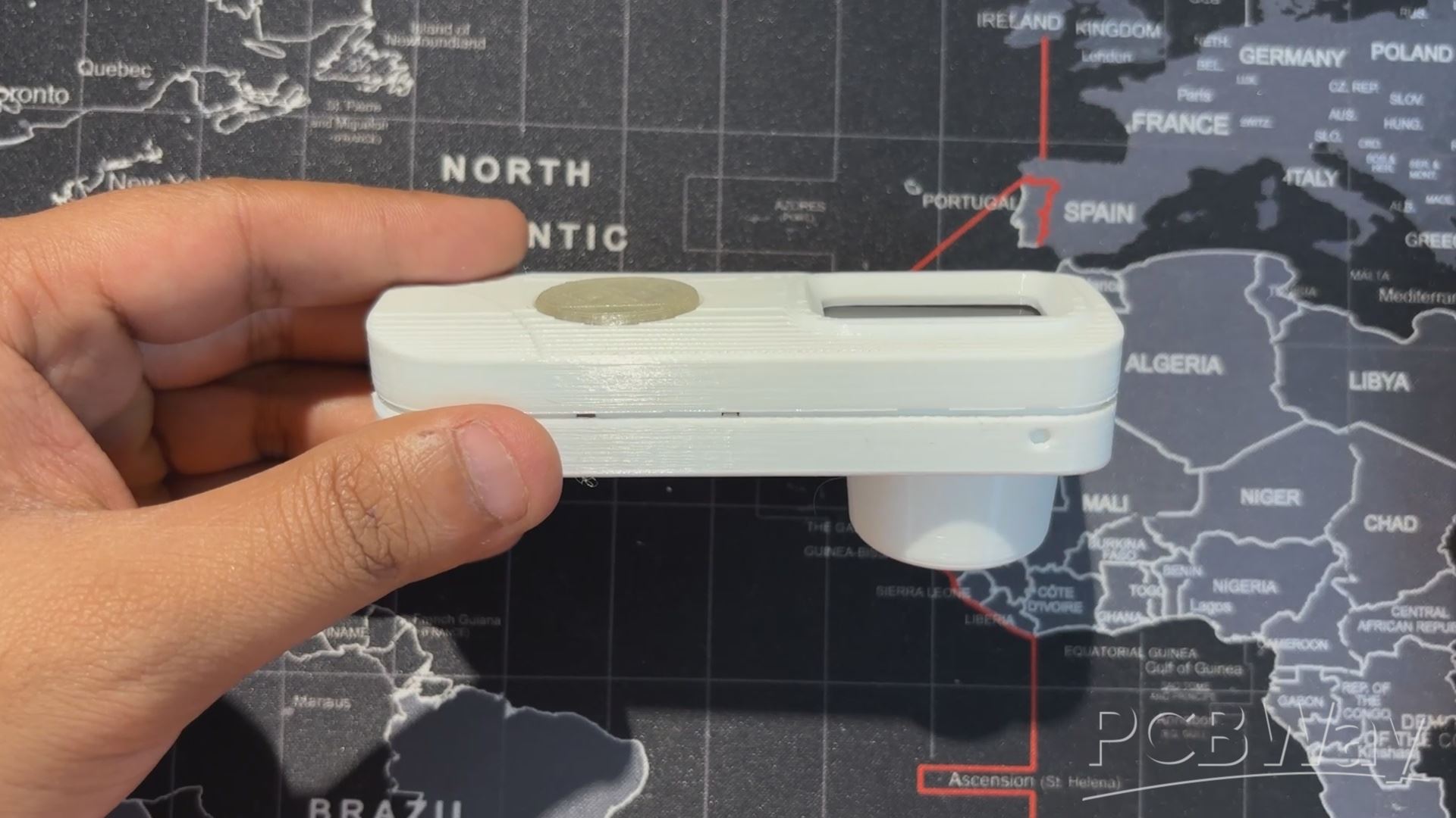
Using the design of our original Medic Mini, we kept the overall idea but simplified the front. The three buttons were removed and replaced with a single elliptical‑shaped button with an actuator that presses the switch connected to GPIO18. The front enclosure remains almost the same, while the back enclosure was completely redesigned. A circular section was added to hold the temperature sensor securely and give the device a temperature gun‑like design.
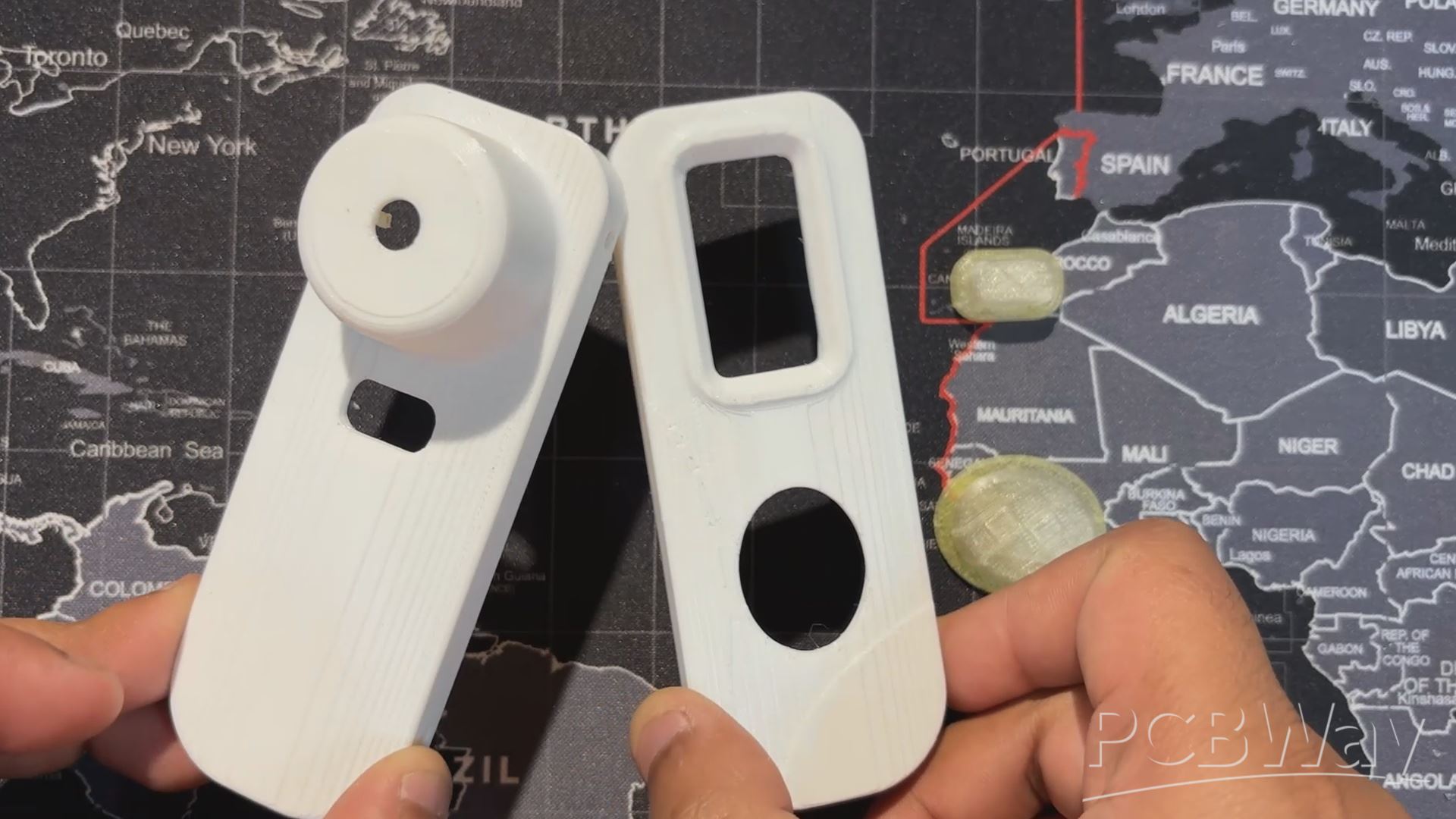
Overall, the build consists of a front and back enclosure, along with two switch actuators, one for taking temperature readings and one for power ON/OFF.
Both enclosures were printed in high‑speed PLA on the Anycubic Kobra S1, while the switch actuators were printed in transparent PLA.
ASSEMBLY PROCESS

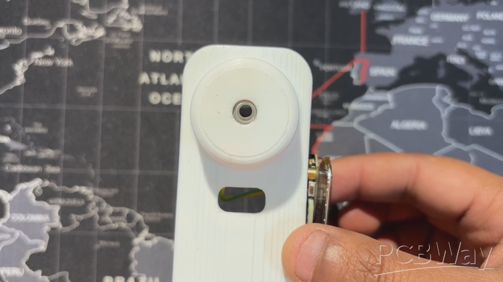
We start the assembly process by adding the MLX90614 sensor in its location in the back enclosure, then use hot glue to secure it in place.
Next, in the front enclosure, we add the switch actuator in position.
The main circuit is then flipped over and placed in its slot in the front enclosure, secured with two M2 screws.
The switch actuator for the power ON/OFF button is placed in its position in the back enclosure, after which the front and back enclosures are joined together to close the device.
Finally, using the four mounting holes provided around the perimeter of the design, we insert M2 screws to secure the front and back enclosures, completing the assembly process.
TESTING
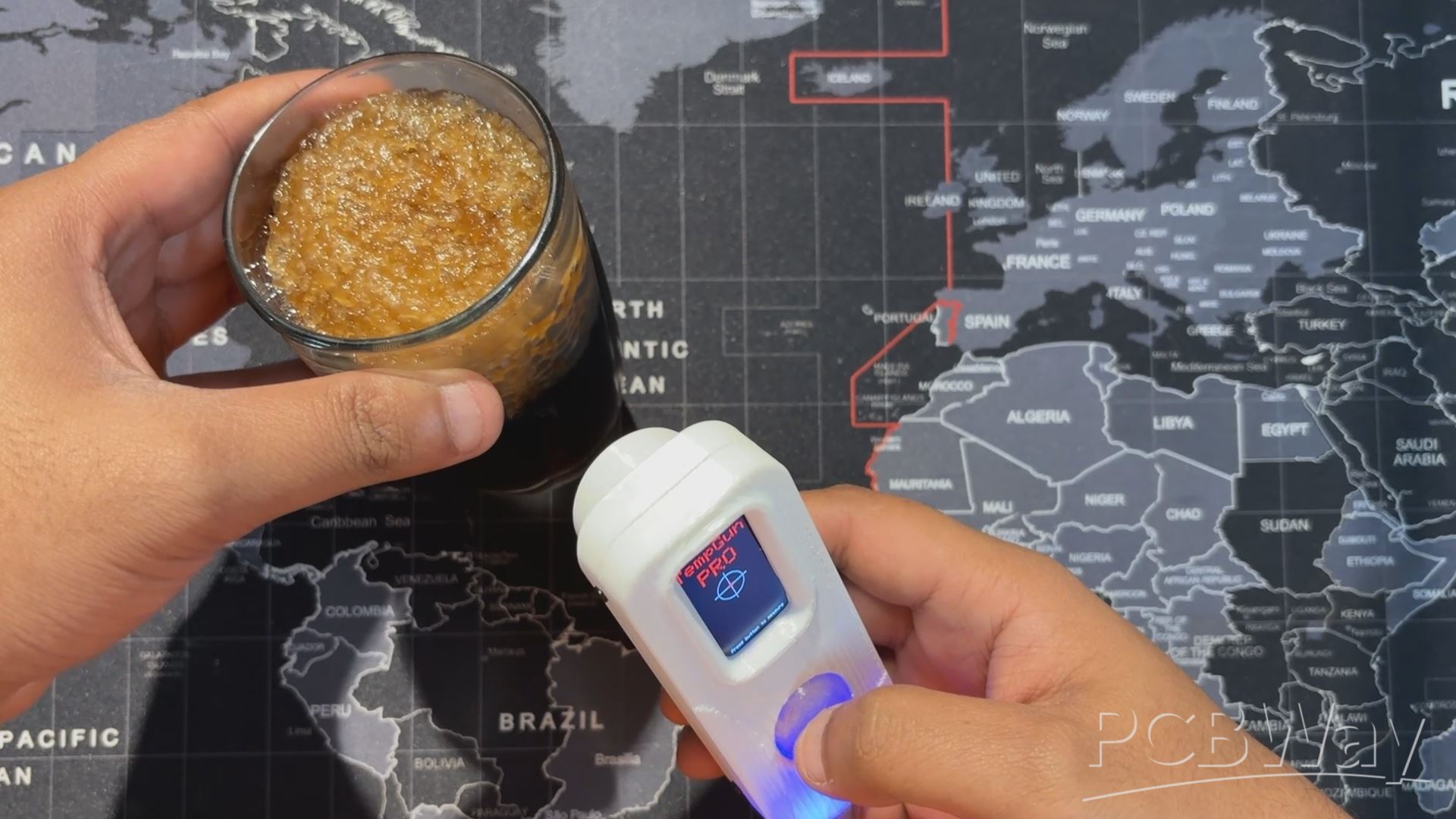

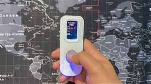
For testing, we started with a cold glass of Coke and measured the outer surface; it read 15.1°C.
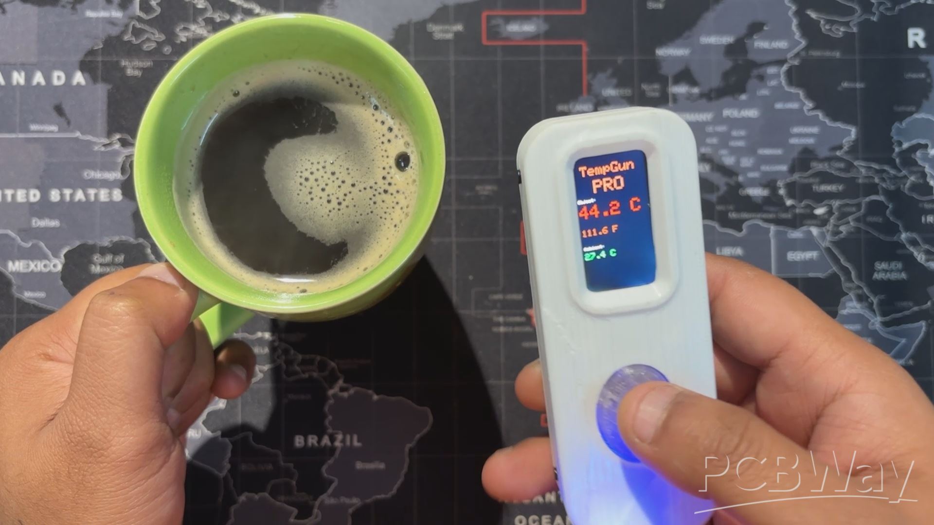
Next, for a hot test, we brewed some black coffee and measured the mug’s outer surface from the same distance, which came out to 44.2°C.
With TempGun Pro, we can measure all kinds of everyday items. The MLX90614 sensor works best at close range, with an ideal measuring distance of 2–5 cm.
For longer‑range measurements, the setup can be upgraded to the MLX90640, which offers a wider capability for thermal detection.
Conclusion
TempGun Pro is a portable, battery‑powered temperature gun that’s easy to carry and delivers accurate close‑range readings. It covers a wide range from –70 °C to +380 °C with about ±0.5 °C tolerance, making it reliable for everyday use.
I now use it to check electronics, 3D printer beds, and other components during work, a perfect alternative while my Fluke is out for repair.
Overall, the project has been a success, and I’ve shared all related files so you can replicate it too. Just remember to give credit.
In addition, we appreciate PCBWAY's support of this project. Visit them for a variety of PCB-related services, such as stencil and PCB assembly services, as well as 3D printing services.
Thanks for reaching this far, and I will be back with a new project pretty soon.
Peace.
#include <Arduino_GFX_Library.h>
#include <Wire.h>
#include <Adafruit_MLX90614.h>

// --- Pin Definitions for WAVESHARE ESP32-C6 LCD BOARD ---
#define LCD_MOSI 6
#define LCD_SCLK 7
#define LCD_CS   14
#define LCD_DC   15
#define LCD_RST  21
#define LCD_BL   22

// I2C pins for MLX90614 (as you confirmed they work)
#define SDA_PIN 4
#define SCL_PIN 5

// Button pin
#define TRIGGER_PIN 18

// --- Global Objects ---

// Create an MLX90614 object
Adafruit_MLX90614 mlx = Adafruit_MLX90614();

// Create the display objects
Arduino_DataBus *bus = new Arduino_ESP32SPI(
  LCD_DC, LCD_CS, LCD_SCLK, LCD_MOSI, GFX_NOT_DEFINED
);
Arduino_GFX *gfx = new Arduino_ST7789(
  bus, LCD_RST, 2, true, 172, 320, 34, 0, 34, 0
);

// --- State and Timing Variables ---

enum GunState {
  READY,
  MEASURING,
  DISPLAY_RESULT
};

GunState currentState = READY;
unsigned long lastMeasurementTime = 0;
const unsigned long resultDisplayTime = 5000; // Display result for 5 seconds

// Button debouncing
bool lastButtonState = HIGH;
unsigned long lastDebounceTime = 0;
const unsigned long debounceDelay = 50;

// --- Drawing Functions ---

void drawReadyScreen() {
  gfx->fillScreen(BLACK);

  // Draw the crosshair
  int centerX = gfx->width() / 2;   // Center of 320px width
  int centerY = gfx->height() / 2;  // Center of 172px height
  gfx->drawCircle(centerX, centerY, 30, WHITE);
  gfx->drawFastHLine(centerX - 40, centerY, 80, WHITE);
  gfx->drawFastVLine(centerX, centerY - 40, 80, WHITE);
  gfx->drawCircle(centerX, centerY, 5, RED);
  gfx->fillCircle(centerX, centerY, 2, RED);

  // --- Draw "TempGun Pro" title ---
  int16_t x1, y1;
  uint16_t w, h;

  // Draw "TempGun"
  gfx->setTextSize(4);
  gfx->setTextColor(RED);
  gfx->getTextBounds("TempGun", 0, 0, &x1, &y1, &w, &h);
  int tempgun_y = 35;
  gfx->setCursor((gfx->width() - w) / 2, tempgun_y);
  gfx->print("TempGun");

  // Draw "PRO" below it, slightly bigger
  gfx->setTextSize(5); // Slightly bigger
  gfx->getTextBounds("PRO", 0, 0, &x1, &y1, &w, &h);
  int pro_y = tempgun_y + h + 2; // Position below "TempGun"
  gfx->setCursor((gfx->width() - w) / 2, pro_y);
  gfx->println("PRO");

  // --- Draw instruction text ---
  gfx->setTextSize(1);
  gfx->setTextColor(WHITE);
  gfx->getTextBounds("Press button to measure", 0, 0, &x1, &y1, &w, &h);
  gfx->setCursor((gfx->width() - w) / 2, gfx->height() - 15);
  gfx->println("Press button to measure");
}

void drawMeasuringScreen() {
  // Redraw crosshair in red to indicate scanning
  int centerX = gfx->width() / 2;
  int centerY = gfx->height() / 2;
  gfx->drawCircle(centerX, centerY, 30, RED);
  gfx->drawFastHLine(centerX - 40, centerY, 80, RED);
  gfx->drawFastVLine(centerX, centerY - 40, 80, RED);

  // Clear the old text and write new text
  int16_t x1, y1;
  uint16_t w, h;
  gfx->setTextSize(1);
  gfx->setTextColor(ORANGE);
  gfx->getTextBounds("SCANNING...", 0, 0, &x1, &y1, &w, &h);
  gfx->fillRect(0, gfx->height() - 15, gfx->width(), h + 5, BLACK);
  gfx->setCursor((gfx->width() - w) / 2, gfx->height() - 15);
  gfx->println("SCANNING...");
}

void drawResultScreen(float objTemp, float ambTemp) {
  gfx->fillScreen(BLACK);

  // --- Draw "TempGun Pro" title ---
  int16_t x1, y1;
  uint16_t w, h;

  // Draw "TempGun"
  gfx->setTextSize(3);
  gfx->setTextColor(ORANGE);
  gfx->getTextBounds("TempGun", 0, 0, &x1, &y1, &w, &h);
  int tempgun_y = 25;
  gfx->setCursor((gfx->width() - w) / 2, tempgun_y);
  gfx->print("TempGun");

  // Draw "PRO" below it, slightly bigger
  gfx->setTextSize(4); // Slightly bigger
  gfx->getTextBounds("PRO", 0, 0, &x1, &y1, &w, &h);
  int pro_y = tempgun_y + h + 2; // Position below "TempGun"
  gfx->setCursor((gfx->width() - w) / 2, pro_y);
  gfx->println("PRO");

  // --- Adjusted Temperature Values Layout ---
  int label_y = 100; // Shifted down from 80
  int value_y_c = label_y + 15; // Position for Celsius value
  int value_y_f = value_y_c + 55; // Position for Fahrenheit value
  int ambient_label_y = value_y_f + 40; // Position for Ambient label
  int ambient_value_y = ambient_label_y + 15; // Position for Ambient value

  // Object Temperature
  gfx->setTextSize(1);
  gfx->setTextColor(WHITE);
  gfx->setCursor(10, label_y);
  gfx->println("Object:");

  gfx->setTextSize(4);
  gfx->setTextColor(RED);
  gfx->setCursor(10, value_y_c);
  gfx->print(objTemp, 1);
  gfx->println(" C");

  // Fahrenheit conversion
  gfx->setTextSize(2);
  gfx->setTextColor(ORANGE);
  gfx->setCursor(10, value_y_f);
  gfx->print((objTemp * 9.0 / 5.0) + 32.0, 1);
  gfx->println(" F");

  // Ambient Temperature
  gfx->setTextSize(1);
  gfx->setTextColor(WHITE);
  gfx->setCursor(10, ambient_label_y);
  gfx->println("Ambient:");

  gfx->setTextSize(2);
  gfx->setTextColor(GREEN);
  gfx->setCursor(10, ambient_value_y);
  gfx->print(ambTemp, 1);
  gfx->println(" C");
}

void drawSensorErrorScreen() {
  gfx->fillScreen(BLACK);
  gfx->setCursor(10, 80);
  gfx->setTextSize(2);
  gfx->setTextColor(RED);
  gfx->println("Sensor Error!");
  gfx->setCursor(10, 110);
  gfx->println("Check wiring &");
  gfx->setCursor(10, 140);
  gfx->println("I2C address.");
}

// --- Main Arduino Functions ---

void setup() {
  Serial.begin(115200);
  delay(1000);
  Serial.println("SETUP: Starting...");

  Wire.begin(SDA_PIN, SCL_PIN);

  Serial.println("SETUP: Finding MLX90614 sensor...");
  if (!mlx.begin()) {
    Serial.println("SETUP: ERROR - Failed to find MLX90614 sensor.");
    pinMode(LCD_BL, OUTPUT);
    digitalWrite(LCD_BL, HIGH);
    gfx->begin();
    drawSensorErrorScreen();
    while (1);
  }
  Serial.println("SETUP: MLX90614 sensor found.");

  Serial.println("SETUP: Initializing Display...");
  pinMode(LCD_BL, OUTPUT);
  digitalWrite(LCD_BL, HIGH);
  gfx->begin();
  Serial.println("SETUP: Display initialized.");

  pinMode(TRIGGER_PIN, INPUT_PULLUP);
  Serial.println("SETUP: Button initialized.");

  Serial.println("SETUP: Drawing ready screen.");
  drawReadyScreen();
  Serial.println("SETUP: Complete. Starting loop.");
}

void loop() {
  static unsigned long lastHeartbeat = 0;
  if (millis() - lastHeartbeat > 5000) {
    Serial.println("LOOP: Heartbeat - loop is running.");
    lastHeartbeat = millis();
  }

  int reading = digitalRead(TRIGGER_PIN);
  if (reading != lastButtonState) {
    lastDebounceTime = millis();
  }

  if ((millis() - lastDebounceTime) > debounceDelay) {
    if (reading == LOW && currentState == READY) {
      Serial.println("LOOP: Button pressed. Starting measurement.");
      currentState = MEASURING;
      lastMeasurementTime = millis();
      drawMeasuringScreen();
    }
  }
  lastButtonState = reading;

  switch (currentState) {
    case READY:
      break;

    case MEASURING:
      if (millis() - lastMeasurementTime > 500) {
        Serial.println("LOOP: Taking temperature reading...");
        float objectTemp = mlx.readObjectTempC();
        float ambientTemp = mlx.readAmbientTempC();

        Serial.print("LOOP: Object Temp: "); Serial.print(objectTemp); Serial.println(" C");
        Serial.print("LOOP: Ambient Temp: "); Serial.print(ambientTemp); Serial.println(" C");

        drawResultScreen(objectTemp, ambientTemp);
        currentState = DISPLAY_RESULT;
        lastMeasurementTime = millis();
      }
      break;

    case DISPLAY_RESULT:
      if (millis() - lastMeasurementTime > resultDisplayTime) {
        Serial.println("LOOP: Result display timeout. Returning to ready.");
        currentState = READY;
        drawReadyScreen();
      }
      break;
  }
}

TempGun Pro
Project images are for reference only. Actual production is based on the manufacturing files on the project page.
Please review the designer's notes (e.g., PCB thickness) and select the appropriate options.
PCBWay is not responsible
for issues caused by unsuitable parameter selections.
For more important ordering information, please refer to
Read More


Raspberry Pi 5 7 Inch Touch Screen IPS 1024x600 HD LCD HDMI-compatible Display for RPI 4B 3B+ OPI 5 AIDA64 PC Secondary Screen(Without Speaker)
BUY NOW


- Comments(1)
- Likes(1)
More by Arnov Arnov sharma
-
 DIY XBOX Controller
Greetings everyone, and welcome back. Here's something fun and custom.This is my version of an Xbox ...
DIY XBOX Controller
Greetings everyone, and welcome back. Here's something fun and custom.This is my version of an Xbox ...
-
 Pocket SNES
Greetings everyone, and welcome back! Today, I’ve got something fun and tiny to share—the Pocket SNE...
Pocket SNES
Greetings everyone, and welcome back! Today, I’ve got something fun and tiny to share—the Pocket SNE...
-
 Batocera Arcade Box
Greetings everyone and welcome back, Here's something. Fun and nostalgic. Right now, we are using ou...
Batocera Arcade Box
Greetings everyone and welcome back, Here's something. Fun and nostalgic. Right now, we are using ou...
-
 64x32 Matrix Panel Setup with PICO 2
Greetings everyone and welcome back.So here's something fun and useful: a Raspberry Pi Pico 2-powere...
64x32 Matrix Panel Setup with PICO 2
Greetings everyone and welcome back.So here's something fun and useful: a Raspberry Pi Pico 2-powere...
-
 Portable Air Quality Meter
Hello everyone, and welcome back! Today, I have something incredibly useful for you—a Portable Air Q...
Portable Air Quality Meter
Hello everyone, and welcome back! Today, I have something incredibly useful for you—a Portable Air Q...
-
 WALKPi PCB Version
Greetings everyone and welcome back, This is the WalkPi, a homebrew audio player that plays music fr...
WALKPi PCB Version
Greetings everyone and welcome back, This is the WalkPi, a homebrew audio player that plays music fr...
-
 Delete Button XL
Greetings everyone and welcome back, and here's something fun and useful.In essence, the Delete Butt...
Delete Button XL
Greetings everyone and welcome back, and here's something fun and useful.In essence, the Delete Butt...
-
 Arduino Retro Game Controller
Greetings everyone and welcome back. Here's something fun.The Arduino Retro Game Controller was buil...
Arduino Retro Game Controller
Greetings everyone and welcome back. Here's something fun.The Arduino Retro Game Controller was buil...
-
 Super Power Buck Converter
Greetings everyone and welcome back!Here's something powerful, The SUPER POWER BUCK CONVERTER BOARD ...
Super Power Buck Converter
Greetings everyone and welcome back!Here's something powerful, The SUPER POWER BUCK CONVERTER BOARD ...
-
 Pocket Temp Meter
Greetings and welcome back.So here's something portable and useful: the Pocket TEMP Meter project.As...
Pocket Temp Meter
Greetings and welcome back.So here's something portable and useful: the Pocket TEMP Meter project.As...
-
 Pico Powered DC Fan Driver
Hello everyone and welcome back.So here's something cool: a 5V to 12V DC motor driver based around a...
Pico Powered DC Fan Driver
Hello everyone and welcome back.So here's something cool: a 5V to 12V DC motor driver based around a...
-
 Mini Solar Light Project with a Twist
Greetings.This is the Cube Light, a Small and compact cube-shaped emergency solar light that boasts ...
Mini Solar Light Project with a Twist
Greetings.This is the Cube Light, a Small and compact cube-shaped emergency solar light that boasts ...
-
 PALPi V5 Handheld Retro Game Console
Hey, Guys what's up?So this is PALPi which is a Raspberry Pi Zero W Based Handheld Retro Game Consol...
PALPi V5 Handheld Retro Game Console
Hey, Guys what's up?So this is PALPi which is a Raspberry Pi Zero W Based Handheld Retro Game Consol...
-
 DIY Thermometer with TTGO T Display and DS18B20
Greetings.So this is the DIY Thermometer made entirely from scratch using a TTGO T display board and...
DIY Thermometer with TTGO T Display and DS18B20
Greetings.So this is the DIY Thermometer made entirely from scratch using a TTGO T display board and...
-
 Motion Trigger Circuit with and without Microcontroller
GreetingsHere's a tutorial on how to use an HC-SR505 PIR Module with and without a microcontroller t...
Motion Trigger Circuit with and without Microcontroller
GreetingsHere's a tutorial on how to use an HC-SR505 PIR Module with and without a microcontroller t...
-
 Motor Driver Board Atmega328PU and HC01
Hey, what's up folks here's something super cool and useful if you're making a basic Robot Setup, A ...
Motor Driver Board Atmega328PU and HC01
Hey, what's up folks here's something super cool and useful if you're making a basic Robot Setup, A ...
-
 Power Block
Hey Everyone what's up!So this is Power block, a DIY UPS that can be used to power a bunch of 5V Ope...
Power Block
Hey Everyone what's up!So this is Power block, a DIY UPS that can be used to power a bunch of 5V Ope...
-
 Goku PCB Badge V2
Hey everyone what's up!So here's something SUPER cool, A PCB Board themed after Goku from Dragon Bal...
Goku PCB Badge V2
Hey everyone what's up!So here's something SUPER cool, A PCB Board themed after Goku from Dragon Bal...
-
Programmable Mist Maker - XIAO / QT PY Extension
1054 2 1 -
RadioHAT - Raspberry Pi radio development platform
850 0 2 -
-
-
-
-
ARPS-2 – Arduino-Compatible Robot Project Shield for Arduino UNO
3316 0 6 -
A Compact Charging Breakout Board For Waveshare ESP32-C3
3920 3 8 -
AI-driven LoRa & LLM-enabled Kiosk & Food Delivery System
4309 2 2


