


Components
|
|
DC BO MOTORQuadStore
|
x 1 | |
|
|
Arduino_UNO_R3 |
x 1 | |
|
|
Arduino UNO R3 SHIELD |
x 1 | |
|
|
DC Stepper MotorQuadStore
|
x 1 | |
|
|
UL2003QuadStore
|
x 1 | |
|
|
L298N |
x 1 | |
|
|
ER14250H |
x 1 | |
|
|
IR remoteRobocraze
|
x 1 | |
|
|
IR recieverRobocraze
|
x 1 | |

|
Mini Breadboard |
x 1 |
Tools, APP Software Used etc.

|
arduino IDEArduino
|
Description
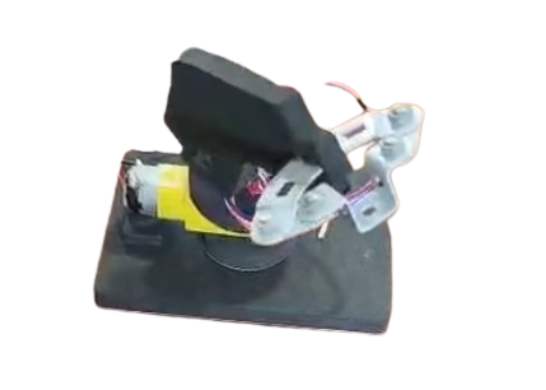
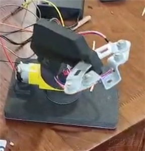
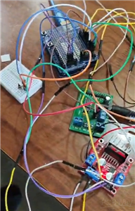
Robotic Arm
This my DIY robotic arm which is made up of foam and double sided tapes. There is an arduino uno r3 for the code. It is connected to two motors via drivers. The DC BO motor turns the arm right and left. The DC stepper motor turns it up and down. There is also a Q-box processor which is a custom driver thingy only avaliable in the QuadStore where I got most of my products from. It is only used for the power source since I only had a 6v barrel jack battery. It also connects the gnds togther. There is a metal part on the hand help with screws used the push buttons. there is also a breadboard which has an IR reciever to control the robotic arm with an IR remote.
Code
Roboarm_code
roboarm.ino
C/C++
#include <IRremote.h>

int RECV_PIN = 5;//The definition of the infrared receiver pin 11
IRrecv irrecv(RECV_PIN);
decode_results results;
int speed = 15;
int Pin0 = 8;
int Pin1 = 9;
int Pin2 = 10;
int Pin3 = 11;

unsigned long lastSignalTime = 0;


int _step = 512;
int _speed = 1;
void setup()
{
 pinMode(Pin0, OUTPUT);
 pinMode(Pin1, OUTPUT);
 pinMode(Pin2, OUTPUT);
 pinMode(Pin3, OUTPUT);
 pinMode(2,OUTPUT);
 pinMode(3,OUTPUT);
 pinMode(4,OUTPUT);
 Serial.begin(9600);
 irrecv.enableIRIn();

}

void loop()
{
  if (irrecv.decode(&results)) {

    Serial.println(results.value, HEX);
    irrecv.resume();

  }
  unsigned long value = results.value;


  lastSignalTime = millis();  // remember time

  if (value==0xFFE01F){
      Speed(speed);
       Step(5);
  }
  else if (value==0xFFA857){
      Speed(speed);
       Step(-5);

  }
  else if (value==0xFF02FD){
      digitalWrite(3,LOW);
      digitalWrite(4,HIGH);
      digitalWrite(2,HIGH);
      delay(50);
      stopMotor();
  }
  else if (value==0xFF22DD){
      digitalWrite(2,LOW);
      digitalWrite(4,HIGH);
      digitalWrite(3,HIGH);
      delay(50);
      stopMotor();
  }


  if (millis() - lastSignalTime > 200) {
    stopMotor();
  }


}
void Speed(int stepperspeed)
{
    _speed = 15 - stepperspeed;
    if( _speed<1){
     _speed = 1;
    }
    if( _speed>15){
     _speed = 15;
    }
}
void Step(int _step)
{
  if(_step>=0){
    for(int i=0;i<_step;i++){
      setStep(1, 0, 0, 1);
      delay(_speed);
      setStep(1, 0, 0, 0);
      delay(_speed);
      setStep(1, 1, 0, 0);
      delay(_speed);
      setStep(0, 1, 0, 0);
      delay(_speed);
      setStep(0, 1, 1, 0);
      delay(_speed);
      setStep(0, 0, 1, 0);
      delay(_speed);
      setStep(0, 0, 1, 1);
      delay(_speed);
      setStep(0, 0, 0, 1);
      delay(_speed);
    }
  }else{
     for(int i=_step;i<0;i++){
      setStep(0, 0, 0, 1);
      delay(_speed);
      setStep(0, 0, 1, 1);
      delay(_speed);
      setStep(0, 0, 1, 0);
      delay(_speed);
      setStep(0, 1, 1, 0);
      delay(_speed);
      setStep(0, 1, 0, 0);
      delay(_speed);
      setStep(1, 1, 0, 0);
      delay(_speed);
      setStep(1, 0, 0, 0);
      delay(_speed);
      setStep(1, 0, 0, 1);
      delay(_speed);
    }
   }
}
void setStep(int a, int b, int c, int d)
{
    digitalWrite(Pin0, a);
    digitalWrite(Pin1, b);
    digitalWrite(Pin2, c);
    digitalWrite(Pin3, d);
}


void stopMotor(){
  digitalWrite(4,LOW);
  digitalWrite(3,LOW);
  digitalWrite(2,LOW);
}
Dec 25,2025
407 views
Robotic Arm
This is a DIY electronic robotic arm made with arduino, drivers and motors.
407
1
0
Published: Dec 25,2025
Standard PCB
PCBWay Donate 10% cost To Author

This work is licensed under a Standard Digital File License.
Digital files have a strict non-commercial, personal use only license.
You shall not share, sub-license, sell, rent, host, transfer, or distribute
in any way the digital file or 3D printed versions of this object, nor any
other derivative work of this object in its digital or physical format
(including remixes of this object).
You can not host these files on other digital platforms, web stores or cloud
repositories.
The objects may not be used in any way whatsoever in which you charge money,
collect fees.
- ✖ | No sharing or redistributing in any way of the 3D files or derivatives
- ✖ | No remixing
- ✖ | Non-commercial Use (only for personal use)
Under the
Standard Digital File
License.


Raspberry Pi 5 7 Inch Touch Screen IPS 1024x600 HD LCD HDMI-compatible Display for RPI 4B 3B+ OPI 5 AIDA64 PC Secondary Screen(Without Speaker)
BUY NOW


- Comments(0)
- Likes(1)
Upload photo
You can only upload 5 files in total. Each file cannot exceed 2MB. Supports JPG, JPEG, GIF, PNG, BMP
0 / 10000
 More by Engineer
You may also like
-
Programmable Mist Maker - XIAO / QT PY Extension
450 0 0 -
RadioHAT - Raspberry Pi radio development platform
355 0 1 -
-
-
-
-
ARPS-2 – Arduino-Compatible Robot Project Shield for Arduino UNO
2899 0 6 -
A Compact Charging Breakout Board For Waveshare ESP32-C3
3402 3 8 -
AI-driven LoRa & LLM-enabled Kiosk & Food Delivery System
3726 2 2


