


|
KiCADKicad
|
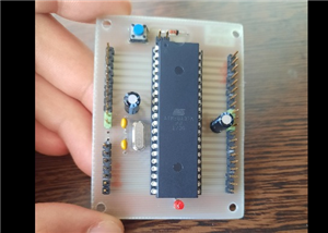
Programming and Development Board for PIC uC
Programmer and development board for PIC microcontrollers
This application is, in addition to a means of practicing practical electronics, a hobby, a way to obtain your own multifunctional board for microcontrollers and a way to use original software (PROGPIC2). This circuit is a multifunctional programmer for the PIC microcontroller family from Microchip. Among the types of uC PIC can be programmed (from those with 8 pins to those with 28 pins). A group of 6 LEDs and 4 push buttons with normally open contact, facilitates the uC testing programmed directly in the socket in the programmer. PIC microcontrollers of another type (over 28 pins, for example PiC16F877) or those packaged in a different type of capsule than the DIP, can be programmed directly in the circuit, through the ICSP connector on the board.
The programming software is called PICPROG2.
It is noted the use of only discrete components, practically without any specialized integrated circuit; this aspect makes this application even more interesting. The conversion of RS232 format signals into TTL (0-5V) signals is performed with general purpose transistors, configured as inverters. This is the case of transistors T1, T2, T3 or T4. The serial port lines, RTS and DTR (pins 7 and 4), from SK2, are used as
clock and data (for uC programming pins, respectively PGC and PGD), and Tx (3), CTS (8) and RI (9) to check and / or control the programming operation.
The entire circuit is powered by at least 15V through connector SK1. The programming value, high value (VPP) of approximately 13.5V (and which is applied on the MCLR / Vpp pin of uC) is obtained from the VR1 controller (L7812). It is mounted in series with the pin reference, to ground, diodes D2 and D3, Thus, at its output, the voltage increases from 12V to 13.5V. From the voltage of 13.5V, there is also the supply voltage of uC, 5V, for the VDD pin, through the VR2 L7805 stabilizer. By switching the jumpers of the SW5 it is possible to choose the working mode: programming, stand-by or testing a program written in uC. Without a jumper, the uC can be inserted into the socket without risk, the programming voltage and the supply voltage do not apply to the uC pins. On the PGM position at SW5A1 it allows the application of the 5V supply voltage (which is signaled by the LD9 LED). The section from SW5B1 at the same time switches the programming voltage of 13.5V to the MCLR pin of the uC. Thus, uC can be programmed with the data arriving from the PC on the DTR line, data that are synchronized with the clock signal on the RTS line. The LD8 LED signals, by activating it, that uC is being programmed. With SW5A1 switched to RUN, uC is normally powered by 5V at the VDD pin and the application registered after programming can be run and tested (viewing the status of the ports defined as LED outputs and / or applying commands from push buttons, on the port line defined as inputs).
For example, when testing an application, the lines defined as outputs (for D1 .... D6) on the board are:
- GP2 and GP4 for 8-pin CPU;
- RC0 ... RC4 for 14-pin CPU;
- RB0 ... RB5 for 18-pin uC;
- RA0 ... RA5 for 28-pin CPU.
As inputs, we use:
- SW1 for GP5 at 8-pin uC;
- SW1 and SW2 for RC5 and RB2 for 14-pin uC;
- pins RA0 ... RA3 at uC with 18 pins for the 4 push buttons;
- for the same 4 switches SW1 ... SW3, pins RB0 ... RB4 from uC with 28 pins.
Applications can be tested with internal or external oscillator (4MHz quartz). The operation is facilitated by jumpers JP1 to P6. The 'Reset' button is also identified on the board. For 8-pin CPU it is not possible to use the external oscillator with quartz crystal. As mentioned above, the SK3 connector facilitates microcontroller programming
mounted in the circuit, without removing or detaching it from the board on which it is mounted. The universally valid programming pins are: VPP, DATA, VDD, CLK and GND.
Note: I am not the original author of this circuit.

Programming and Development Board for PIC uC
Project images are for reference only. Actual production is based on the manufacturing files on the project page.
Please review the designer's notes (e.g., PCB thickness) and select the appropriate options.
PCBWay is not responsible
for issues caused by unsuitable parameter selections.
For more important ordering information, please refer to
Read More


Raspberry Pi 5 7 Inch Touch Screen IPS 1024x600 HD LCD HDMI-compatible Display for RPI 4B 3B+ OPI 5 AIDA64 PC Secondary Screen(Without Speaker)
BUY NOW


- Comments(0)
- Likes(1)
 More by cris 🙂
-
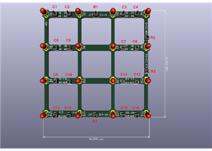
 Dynamic decoration with LEDs and more
Hello everyone!As you can see in the title, we have a circuit with LEDs, many LEDs, it's a 4x4 LEDs ...
Dynamic decoration with LEDs and more
Hello everyone!As you can see in the title, we have a circuit with LEDs, many LEDs, it's a 4x4 LEDs ...
-
 LEDs Stars
Hello everyone! I'm signing up for this competition with a small project designed to attract your a...
LEDs Stars
Hello everyone! I'm signing up for this competition with a small project designed to attract your a...
-
 Audio amplifier with LM386 (and BASS boost)
Hello everyone!Circuit descriptionThe LM386 is quite a ve...
Audio amplifier with LM386 (and BASS boost)
Audio amplifier with LM386 (and BASS boost)Hello everyone!Circuit descriptionThe LM386 is quite a ve...
-
 Audio amplifier 25W TDA2030
A fairly well-known and interesting montagePresentationThe presented audi...
Audio amplifier 25W TDA2030
Audio amplifier 25W TDA2030A fairly well-known and interesting montagePresentationThe presented audi...
-
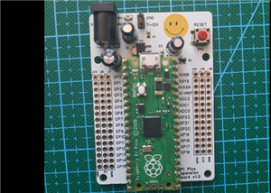 Raspberry Pi Pico Expansion Board
Hello everyone!UPDATE!!!I made some changes, routing in particular, and freed up the board of a few ...
Raspberry Pi Pico Expansion Board
Hello everyone!UPDATE!!!I made some changes, routing in particular, and freed up the board of a few ...
-
 Adjustable voltage power supply
Among the most important electronic devices in the electronics laboratory is the voltage source. Thi...
Adjustable voltage power supply
Among the most important electronic devices in the electronics laboratory is the voltage source. Thi...
-
 Digital Clock with AT89C2051
Circuit OperationShort SW2 presses cycle through displaying the current time in HH:MM and MM:SS form...
Digital Clock with AT89C2051
Circuit OperationShort SW2 presses cycle through displaying the current time in HH:MM and MM:SS form...
-
 Switch based light sensor
Hi!The circuit shown can be used to turn on the light in the garden, or some light panels / advertis...
Switch based light sensor
Hi!The circuit shown can be used to turn on the light in the garden, or some light panels / advertis...
-
 LM3909 flashing indicator
I present to you a circuit which is a little outdated, but quite pleasant for some, I saw that this ...
LM3909 flashing indicator
I present to you a circuit which is a little outdated, but quite pleasant for some, I saw that this ...
-
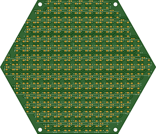 Hexagonal Panel with WS2812B LEDs
Hi makers!I created a hexagonal PCB with many WS2812B LEDs, 144 in total, for which I thought of pla...
Hexagonal Panel with WS2812B LEDs
Hi makers!I created a hexagonal PCB with many WS2812B LEDs, 144 in total, for which I thought of pla...
-
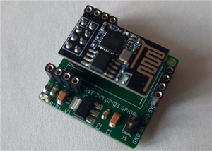
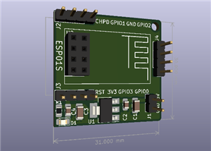 ESP01S Minimal Board
Hi makers!I created this small PCB for ESP01S because before I was using a DIY version and then I bo...
ESP01S Minimal Board
Hi makers!I created this small PCB for ESP01S because before I was using a DIY version and then I bo...
-
 4x4x4 cube with blue LEDs
Hi makers!I know that these days there are many variations of LEDs, for example SMDs are smaller and...
4x4x4 cube with blue LEDs
Hi makers!I know that these days there are many variations of LEDs, for example SMDs are smaller and...
-
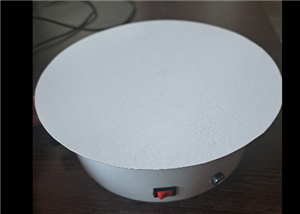 Low cost turntable 😁
Hi makers!I'm entering this competition with a small project that I've wanted to make for some time,...
Low cost turntable 😁
Hi makers!I'm entering this competition with a small project that I've wanted to make for some time,...
-
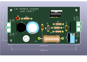 A DIY charger for 12V battery
Hello everyone!I present to you a project that really didn't reach its final state, until recently. ...
A DIY charger for 12V battery
Hello everyone!I present to you a project that really didn't reach its final state, until recently. ...
-
 ESP01 board
Hello PCBWayers!You probably know that ESP01S/01 boards can be a little difficult to use in an easie...
ESP01 board
Hello PCBWayers!You probably know that ESP01S/01 boards can be a little difficult to use in an easie...
-
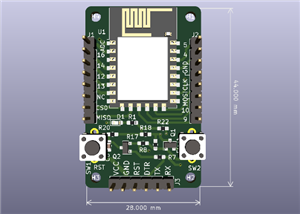 ESP12F Board
Hello makers!Some time ago I had a shopping coupon and I thought about making some simple PCBs with ...
ESP12F Board
Hello makers!Some time ago I had a shopping coupon and I thought about making some simple PCBs with ...
-
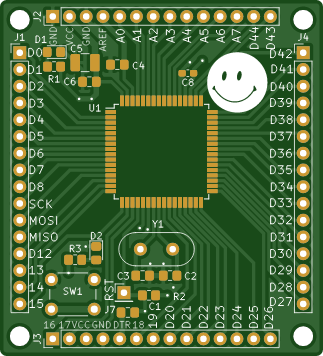
 ATMega32 Board
Hi !I remembered this simple project I made for myself, you can use it with an ATMega32 or ATMega16 ...
ATMega32 Board
Hi !I remembered this simple project I made for myself, you can use it with an ATMega32 or ATMega16 ...
-
 AT90CAN128
Hello makers!Here is a guy who likes to build various, small, electronic circuits, and through this ...
AT90CAN128
Hello makers!Here is a guy who likes to build various, small, electronic circuits, and through this ...
-
Programmable Mist Maker - XIAO / QT PY Extension
1061 2 1 -
RadioHAT - Raspberry Pi radio development platform
867 0 2 -
-
-
-
-
ARPS-2 – Arduino-Compatible Robot Project Shield for Arduino UNO
3323 0 6 -
A Compact Charging Breakout Board For Waveshare ESP32-C3
3933 3 8 -
AI-driven LoRa & LLM-enabled Kiosk & Food Delivery System
4320 2 2


