


PathFinder
Greetings Fellow Travellers, and welcome back.
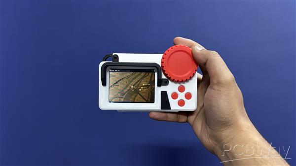
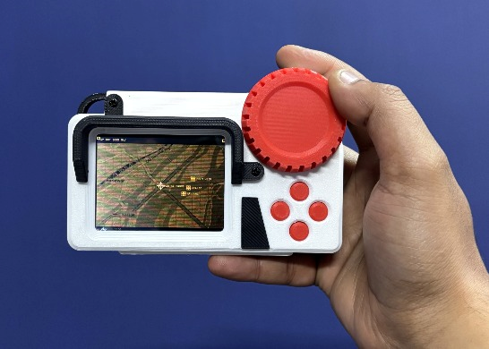
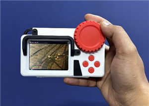
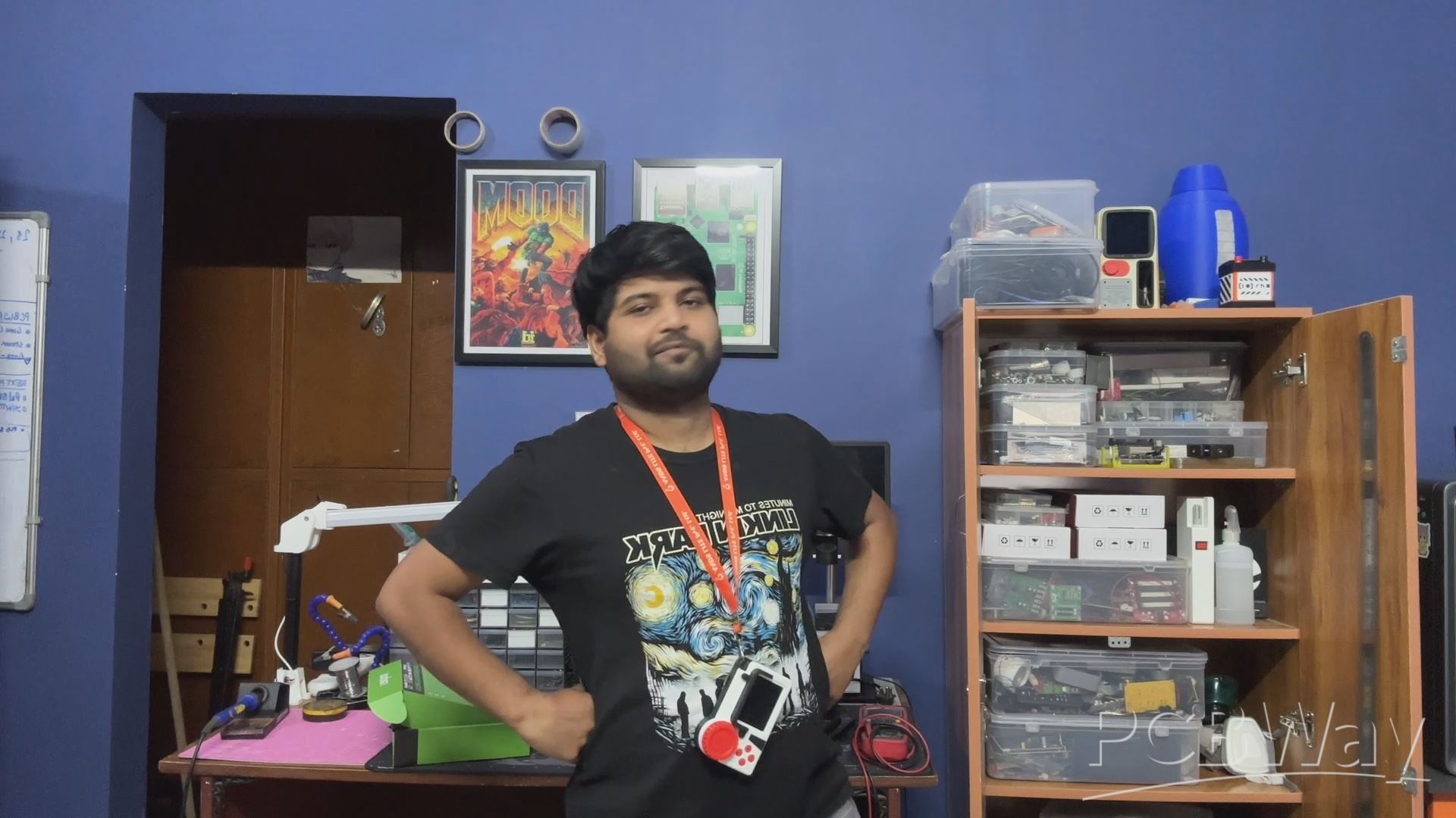
This is PathFinder, a DIY digital map device powered by the UNIHIKER M10, designed to help you find your way.
I go on rides in mountain areas near my hometown, and there, I frequently get no signal in some areas. Relying completely on Google Maps is a no-no; sometimes, due to data issues, maps are not loaded completely, and this can be a nightmare if you are stranded.
This could all be sorted if we had a physical map and some navigation skills. I don’t have a physical map, but I have made a digital map that is loaded on a UNIHIKER M10 board. We can navigate the map using directional buttons. With this, one can help themselves if they are stranded.
For testing this out, I went to a remote area in the mountains near my hometown and used this map to navigate a road I had never been to before. I followed the map and was able to find my way without any issues.
This article covers the complete build process of this project, from the construction process of PCBs to code and device assembly, so let’s get started with the build.
MATERIALS REQUIRED
These were the materials used in this project-
- Custom PCBs (Provided by PCBWAY)
- Unihiker M0 Dev Board
- 3D printed parts
- IP5306 Power Management IC
- 10uF 1206 Capacitors
- Type C port
- Vertical Push Button
- LED 0603 Green
- 1uH Inductor SMD
- Push Buttons 4x4mm size.
HARDWARE-UNIHIKER M1
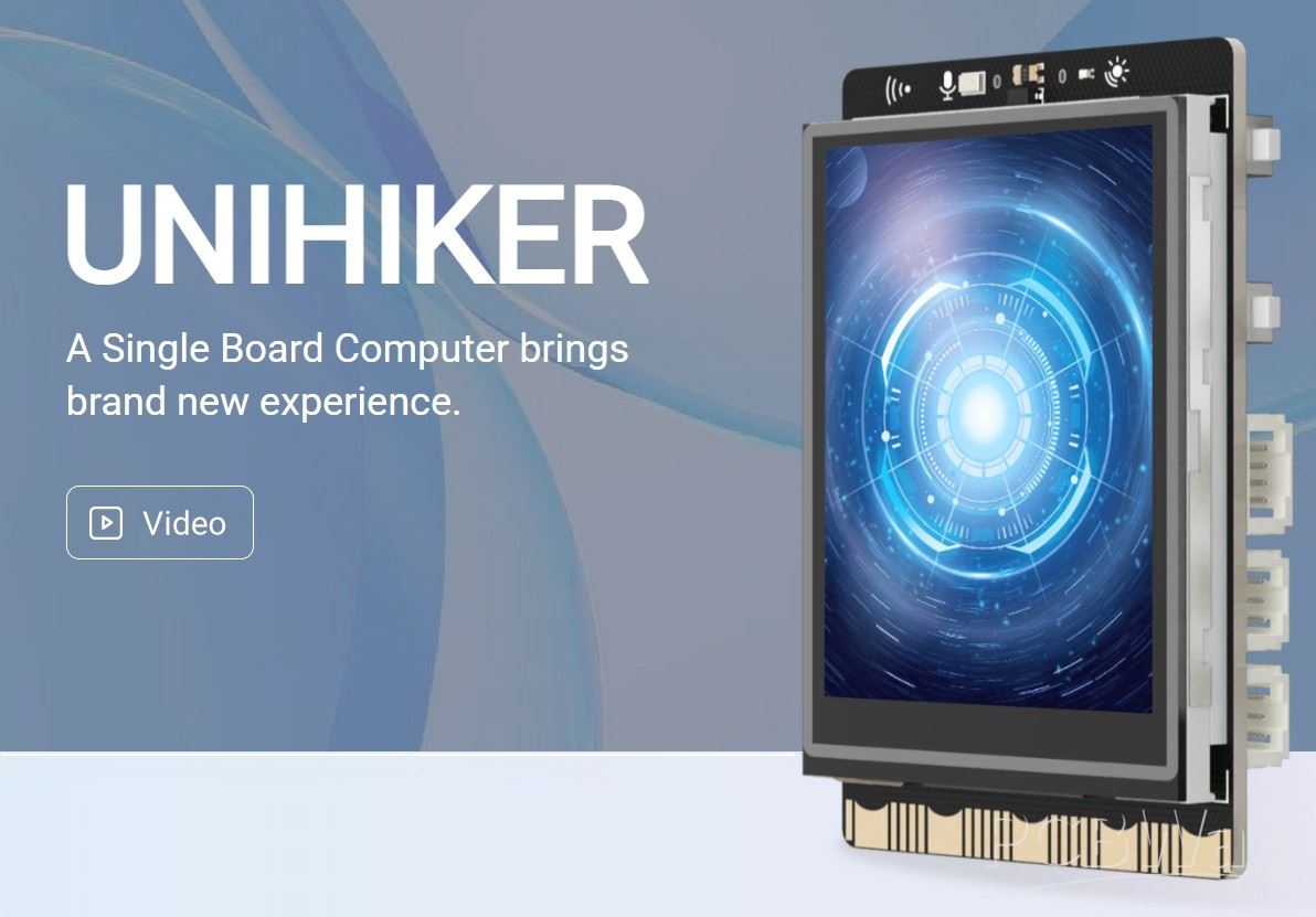
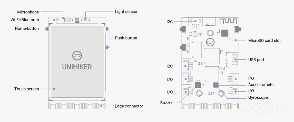
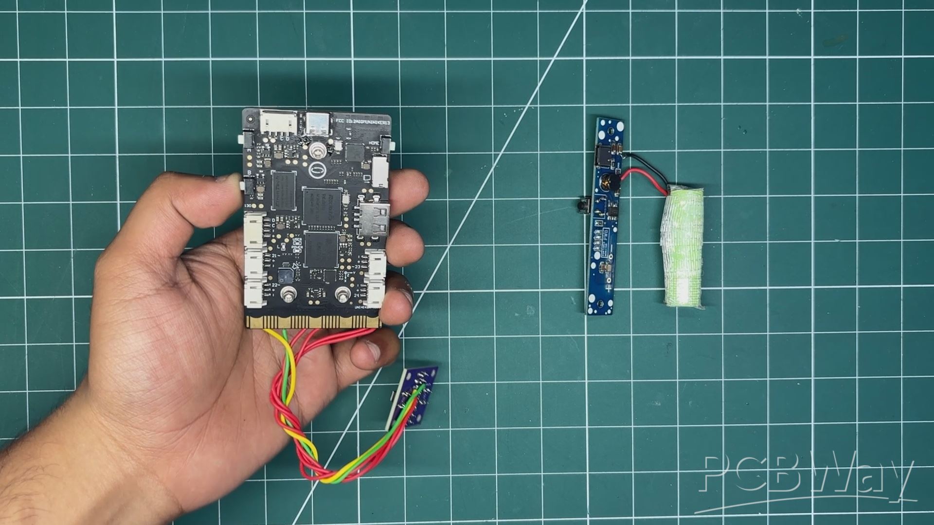
The star of our project is the UNIHIKER M10, which is a single-board computer that is quite unique. It comes with an onboard 2.8-inch touch display and has Wi-Fi and Bluetooth built in.
The thing that makes this device truly unique is the processor and co-processor. It is powered by an RK3308 ARM 64-bit processor, which has 4 cores and is clocked at 1.2GHz. It has 512MB DDR3 RAM and comes with an onboard 16GB eMMC chip.
For controlling GPIOs, it has a co-processor, the GD32VF103C8T6. The name might be long, but it’s a RISC-V processor clocked at 108MHz, with 64KB flash and 32KB SRAM.
The CPU cannot directly control GPIOs, so a co-processor has been added, which we can control using Python. The system controls the co-processor using the PinPong library.
The board is made by DFRobot, and you can check out more details about this board through their well-documented wiki page.
https://www.unihiker.com/products/m10
MAP UI BUILD
The UNIHIKER M10 runs full Debian Linux. Everything on it, including the screen, GPIO pins, and sensors, is controlled via Python, so there’s no Arduino IDE support and, sadly, no C.
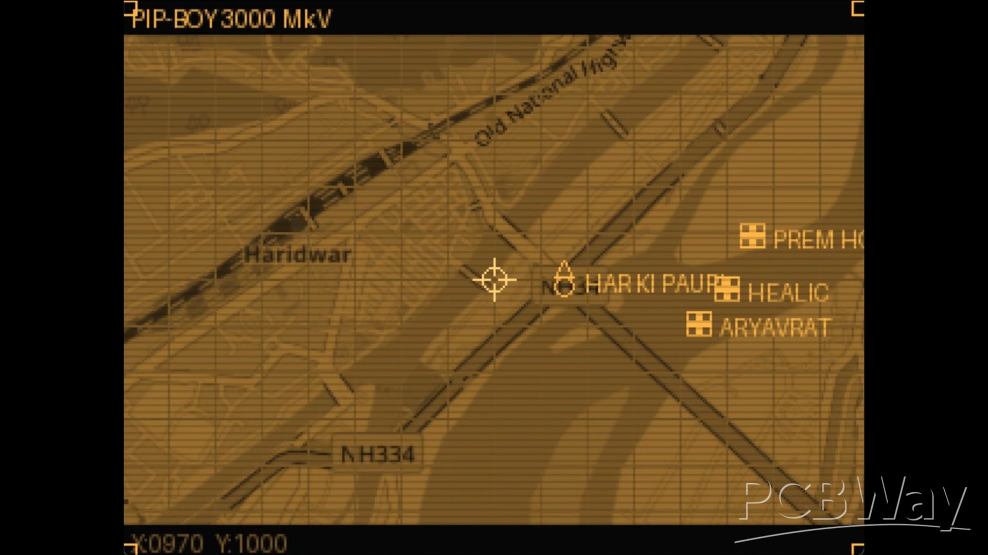
For the map, I took inspiration from the Fallout: New Vegas Pip-Boy 3000 interface, which features an amber tint. Normal maps are boring, and as a Fallout fan, it was my duty to create a map inspired by the Pip-Boy.
Two libraries are used. The first is the UNIHIKER driver, which controls the built-in 240×320 display. Then there’s the PinPong library, which is used to read and write GPIO pins.
Displaying Frames
We first create the image widget once and just update its file on every frame.
gui = GUI() # Create once display_img = gui.draw_image(x=0, y=0, image="/tmp/frame.png") # Every frame: save new image, then update the same widget frame.save("/tmp/frame.png") display_img.config(image="/tmp/frame.png")
Rendering with Pillow
All graphics are composed in memory using Pillow — no framebuffer, no pygame. Each frame goes through:
- Crop a 320×240 viewport from the 2000×2000 map
- Apply an amber tint
- Draw CRT grid + POI icons
- Composite scanline overlay
- Animate crosshair
- Draw HUD bars
- Rotate to landscape
- Save and push
```python from PIL import Image, ImageDraw viewport = self._map.crop((x0, y0, x0 + VIEWPORT_W, y0 + VIEWPORT_H)) frame = viewport.convert("RGBA") draw = ImageDraw.Draw(frame) ```
Amber Tint
The map loads as normal RGB. To get the Pip-Boy phosphor look, the Red channel is used as the brightness source for all three channels:
r, g, b = img.split() img = Image.merge("RGB", ( r, r.point(lambda v: int(v * 0.71)), # amber green r.point(lambda v: int(v * 0.26)), # amber blue ))
Ratios `(1.0, 0.71, 0.26)` match the target amber `(255, 182, 66)`.
Physical Buttons
Buttons are wired to GPIO pins with internal pull-up resistors. When pressed, they pull the pin LOW, so a reading of `0` means "pressed".
from pinpong.board import Board, Pin
Board("unihiker").begin() btn_up = Pin(Pin.P3, Pin.IN, Pin.PULLUP) if btn_up.read_digital() == 0: move_y = -PAN_SPEED if not hasattr(Pin, "PULLUP") and hasattr(Pin, "PULL_UP"): Pin.PULLUP = Pin.PULL_UP
Landscape on a Portrait Screen
The physical display is 240×320 (portrait). I draw into a 320×240 canvas (landscape) and rotate every frame before saving:
frame = frame.rotate(-90, expand=True) # result: 240×320 — fills the screen when held sideways
The Render Loop
Standard fixed-timestep loop — sleep for whatever time is left in the frame budget.
target_fps = 15 frame_time = 1.0 / target_fps while True: t0 = time.time() # ... read buttons, render, push frame ... sleep_t = frame_time - (time.time() - t0) if sleep_t > 0: time.sleep_t)
Libraries
| Library | Install | Purpose | |---|---|---| | `pillow` | `pip install pillow` | All image rendering | | `unihiker` | pre-installed | Push frames to the screen | | `pinpong` | pre-installed | GPIO buttons and buzzer | | `math`, `time`, `os` | standard library | Animation, timing, file checks |
UNIHIKER POWER INPUT
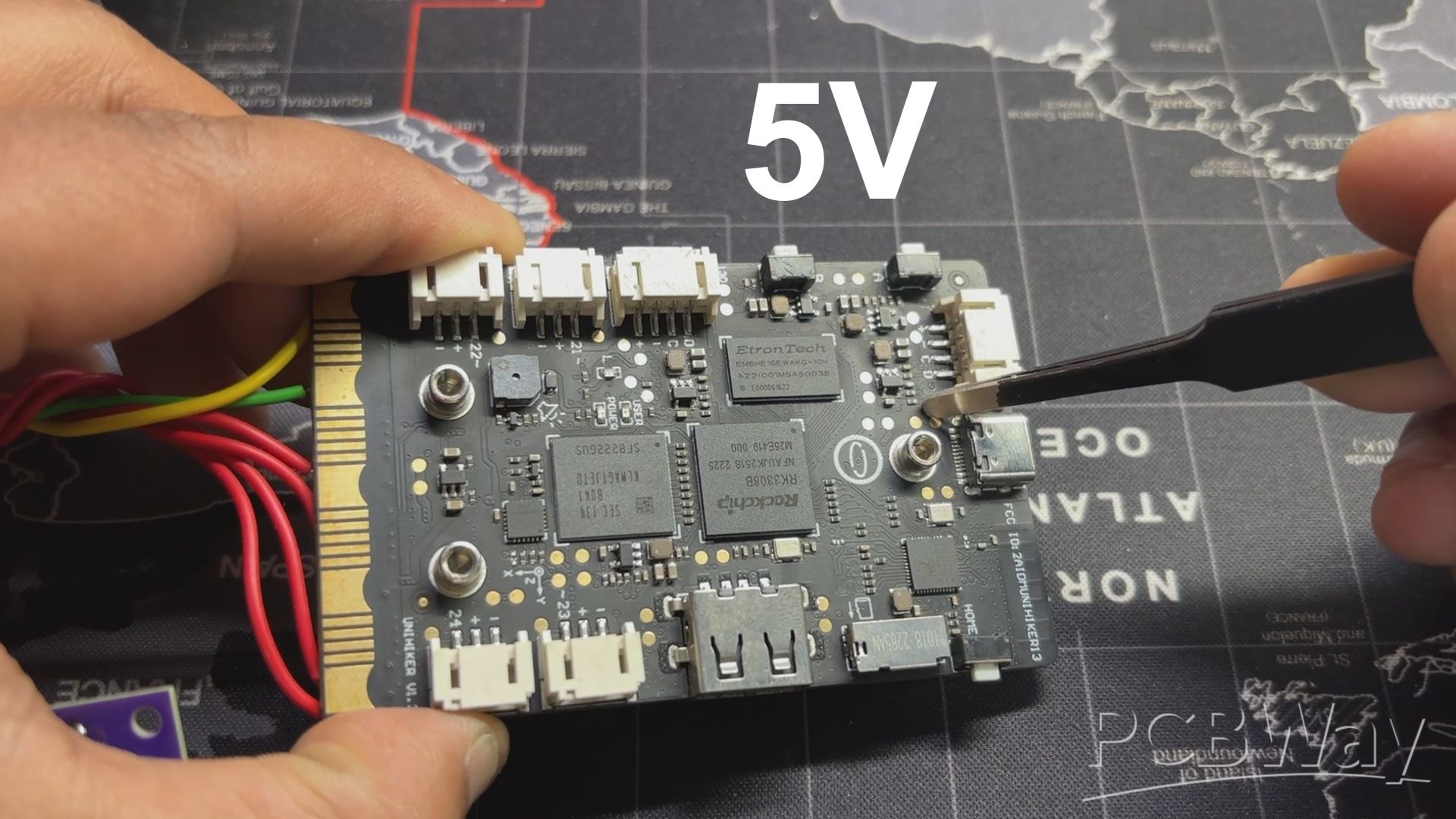
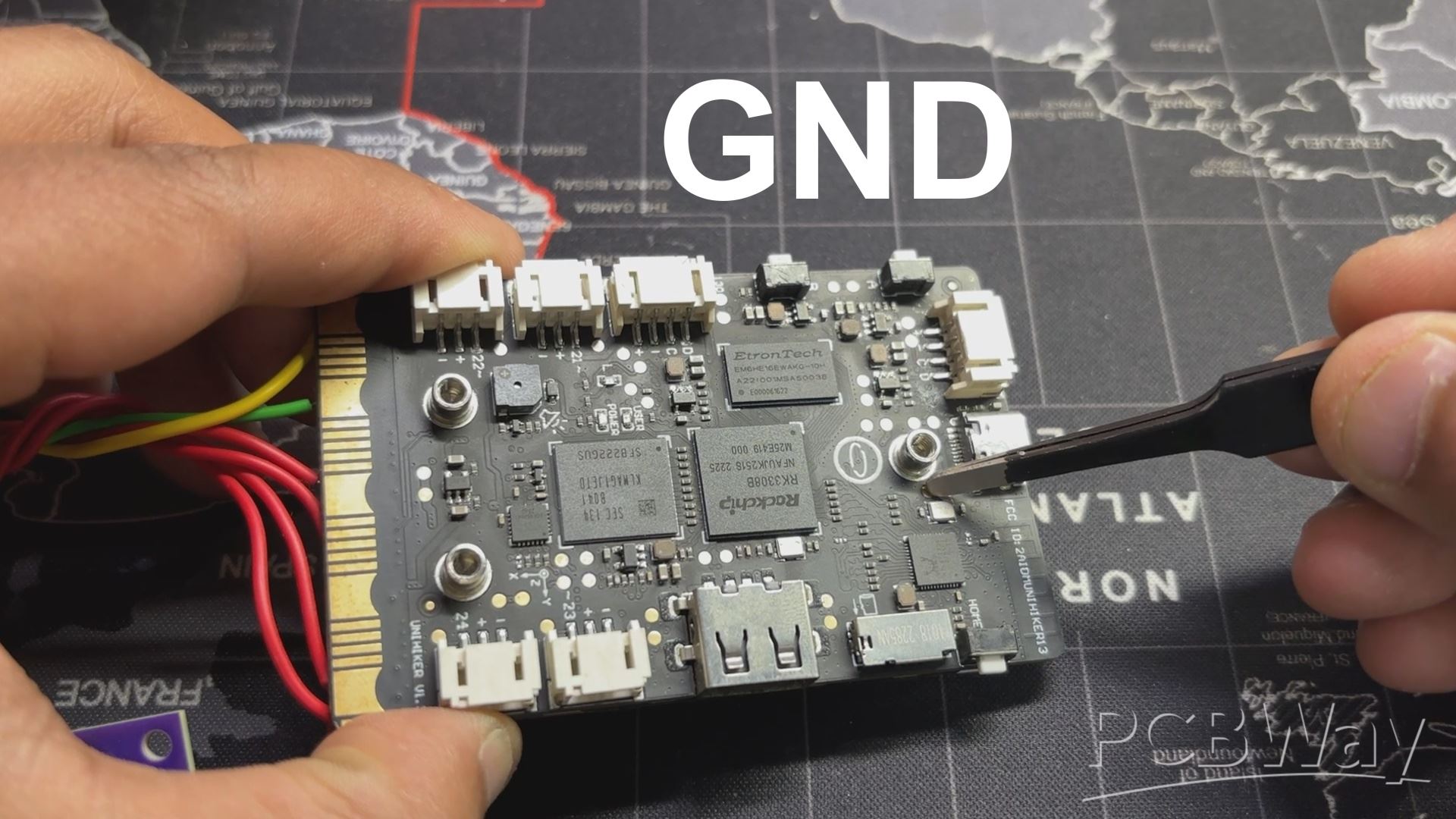
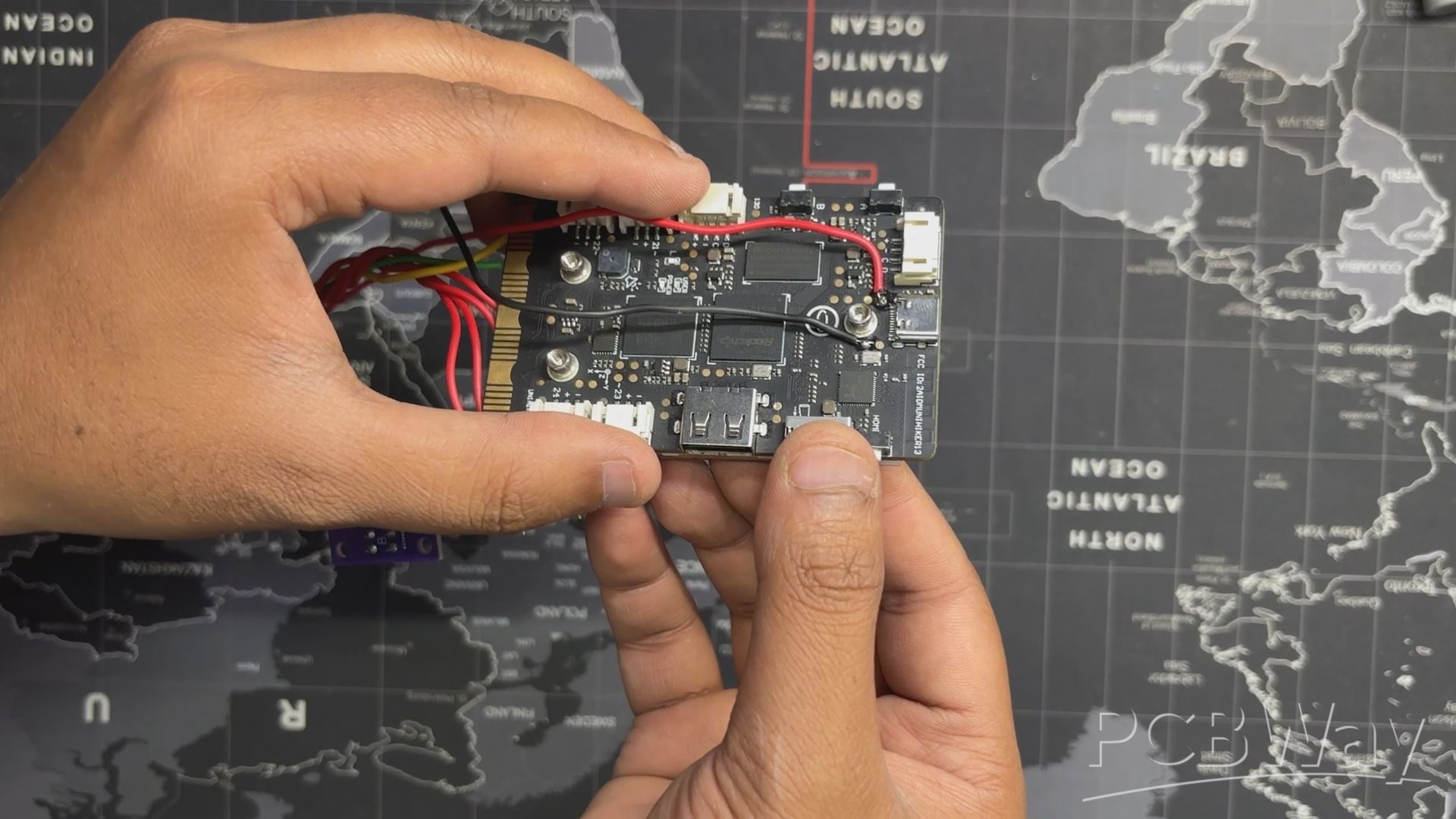
Next, after configuring the map setup, we tackled the UNIHIKER power input problem. The UNIHIKER M10 uses a USB Type-C port as a power input, which provides a stable 5V for the setup to work. The issue with this board is that there is no onboard battery connector.
Near the Type-C port, we find two terminals. The first terminal is connected to the USB Type-C port’s VCC, and the other terminal is connected to GND.
By providing 5V to these two terminals, we can power this board, but for that, we need a stable power source.
3D DESIGN
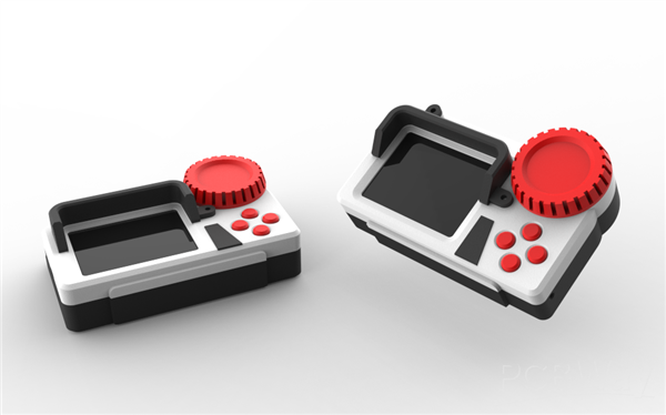
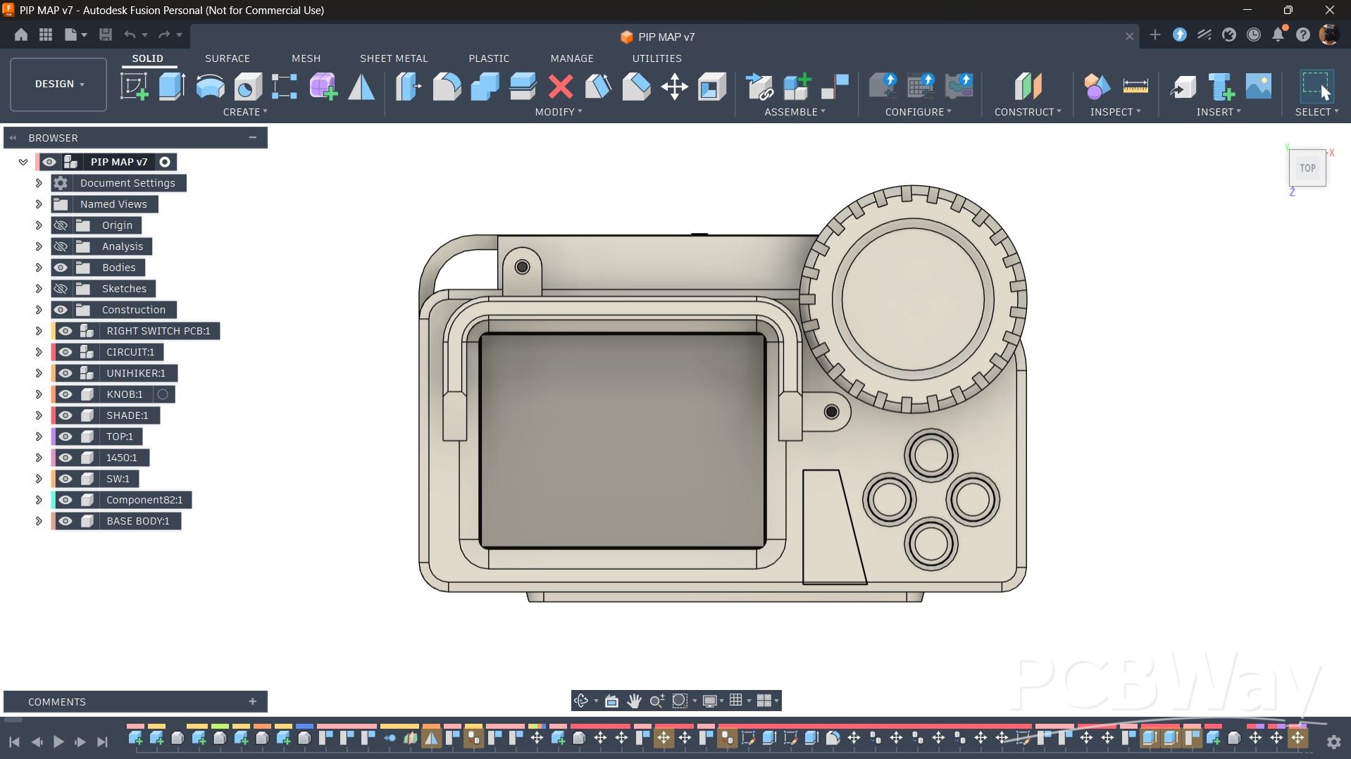
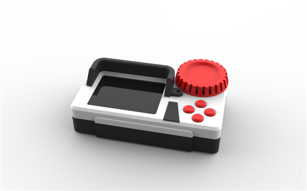
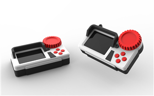
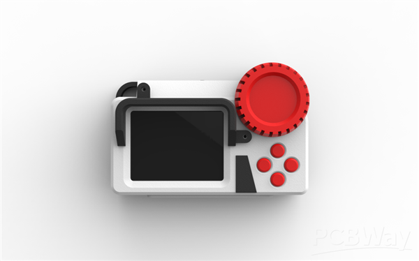
For this project, my idea was to make a device that has a screen with four buttons next to it, inspired by the cyberpunk genre, where there is a strong emphasis on displays, and the form is boxy and symmetrical.
To enhance the design, I added a screen shade part, which also serves a practical purpose. When the device is used outdoors, it provides shade to the display, making it easier to see.
I also added a large knob, which isn’t a practical or functional part and was included purely for aesthetic purposes. Additionally, I added one more part on the front side for aesthetics.
By adding different parts, my goal was to use three colored filaments, red, white, and black, to 3D print the components, creating a great color combination.
Inside the model, there is a proper circuit layout, including the button board. Each circuit has its own mounting screw bosses, where we place the boards and secure them using M2 screws.
We also added openings on one side of the device to access the USB port of the UNIHIKER M10 if we want to reprogram the device. Openings were also added for accessing the USB port of the power module and the on/off push button.
For attaching an ID card strap, we added a hook-like part on one end, where the strap can be connected.
3D PRINTED PARTS
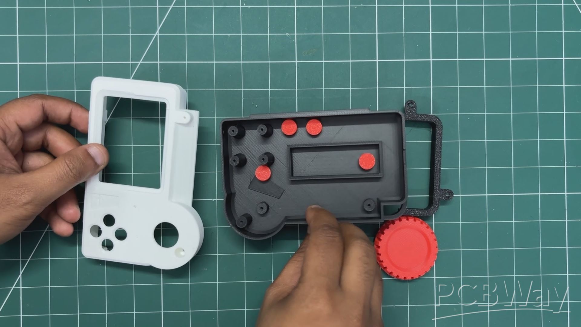
Once the model was finalised, we 3D printed all the parts using Hyper PLA with the same settings, which included a 0.2mm layer height, 25% infill, and tree supports with a 0.3mm Z distance.
The front body was printed with white Hyper PLA. The back body, the shade part, and the aesthetic part were all printed in black Hyper PLA.
Red Hyper PLA was used to print the four switches and the knob part.
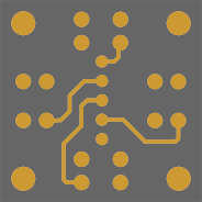
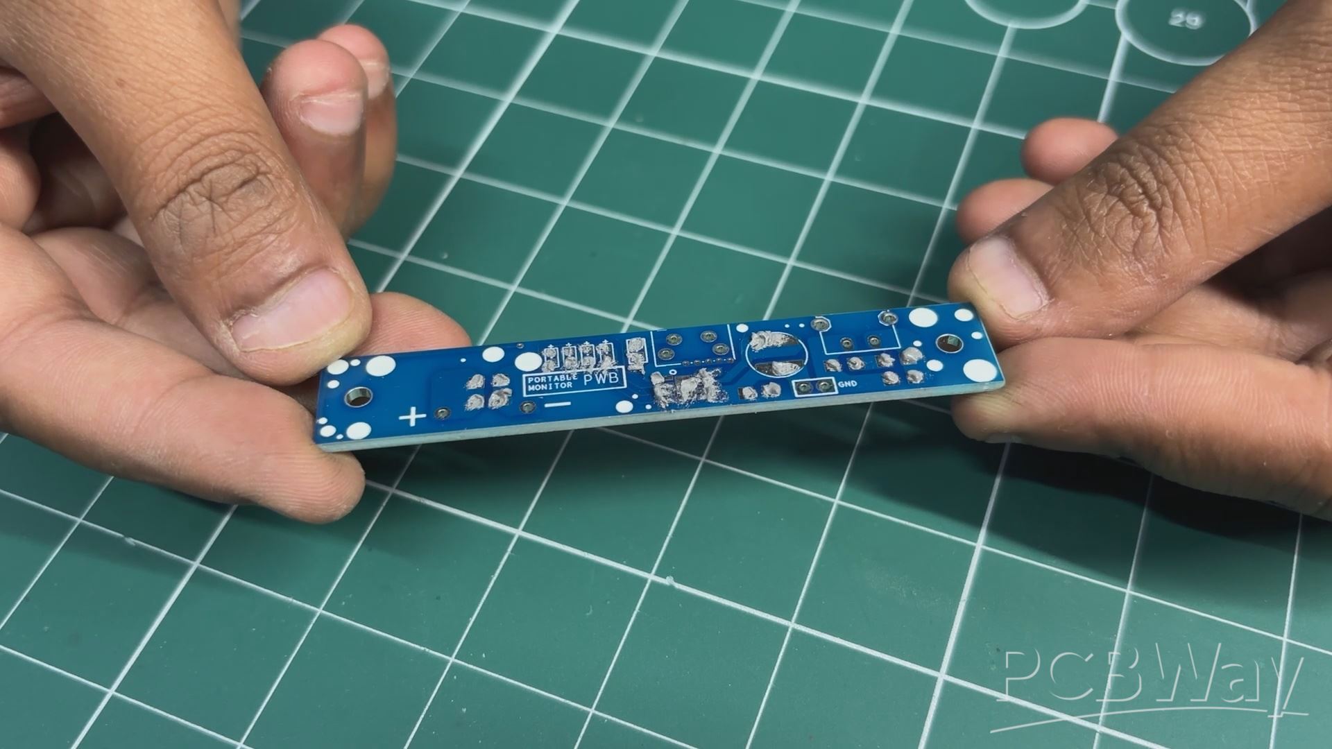
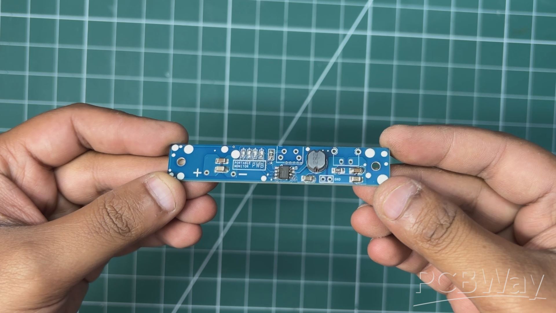
PCB DESIGN- POWER BOARD
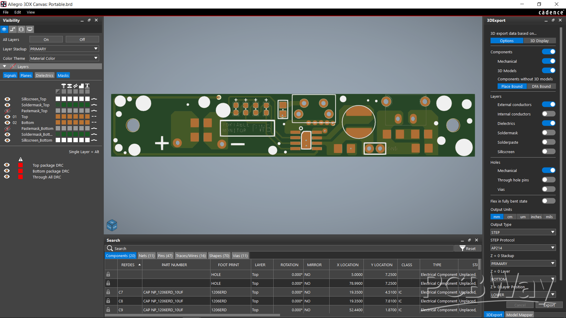
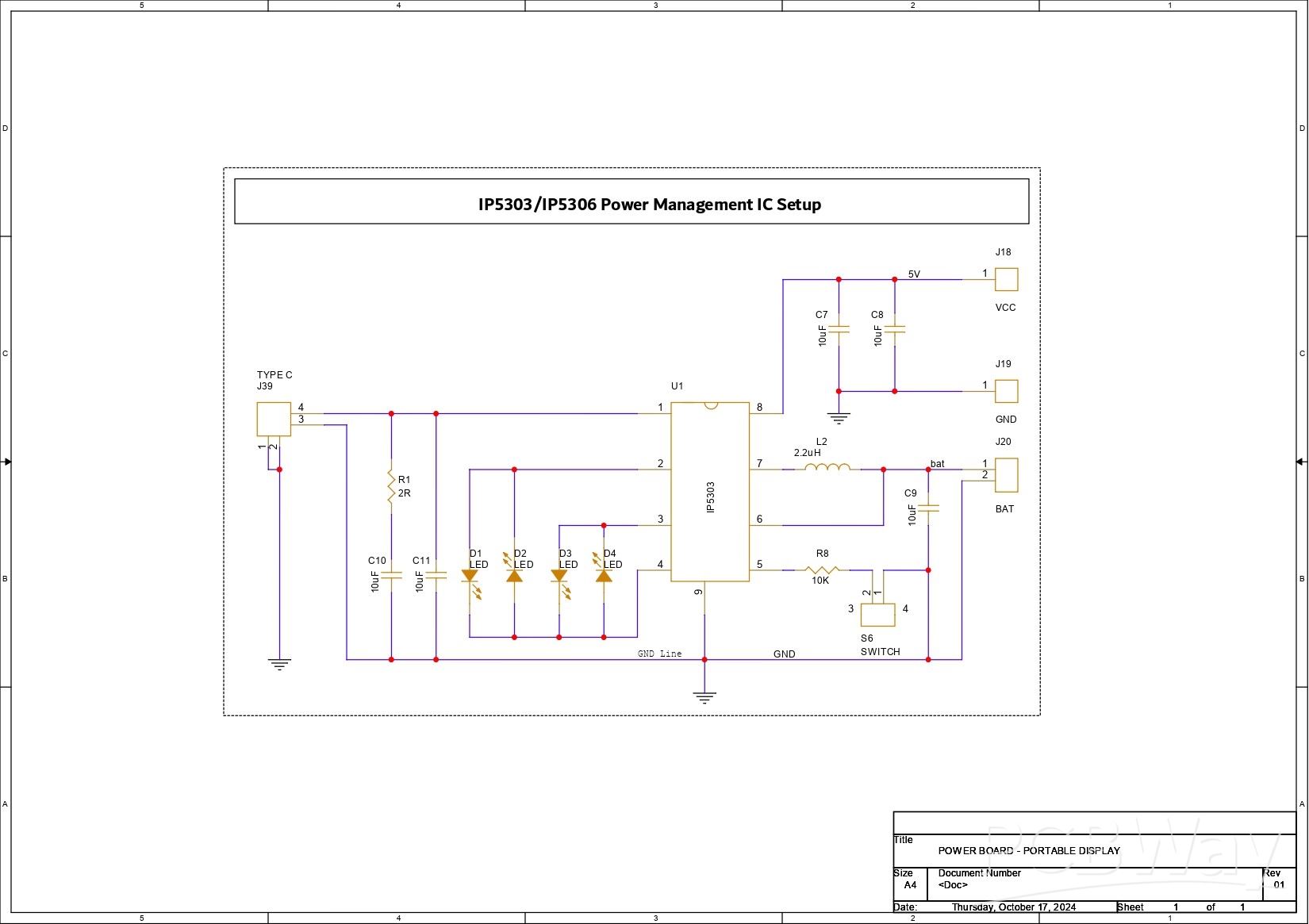
Here, we are reusing the circuit used in my portable display project.
In this circuit, the IP5306 Power Management IC draws a consistent 5V/2A from a 3.7V Li-ion battery. Its high-cut and low-cut characteristics prevent overcharging and overdischarging of the cell.
The charging port we're using is a Type C through-hole port that connects to the IC charging port. Along with the charging port and GND, we included a 10uF filter capacitor and a 10uF capacitor combination with a 2Ohm resistor.
Additionally, four LEDs, which will serve as battery-full indication LEDs, are added to the IC's LED port.
To turn this device on and off, a push button has been added.
Additionally, we added two extra filter capacitors to the IC and GND outputs.
PCBWAY SERVICE
After finalizing the design, I generated the PCB Gerber files and sent them to PCBWay for fabrication
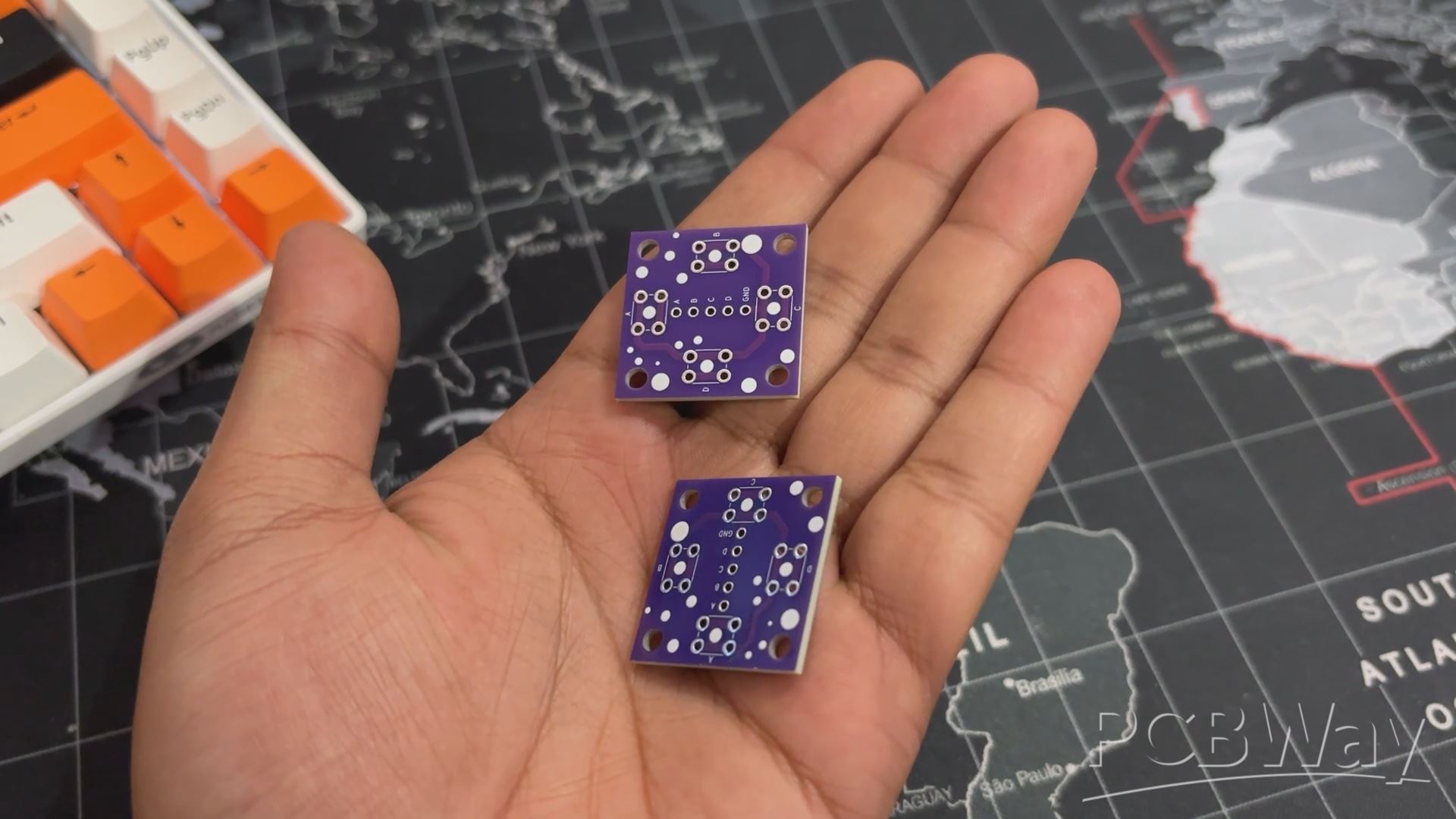
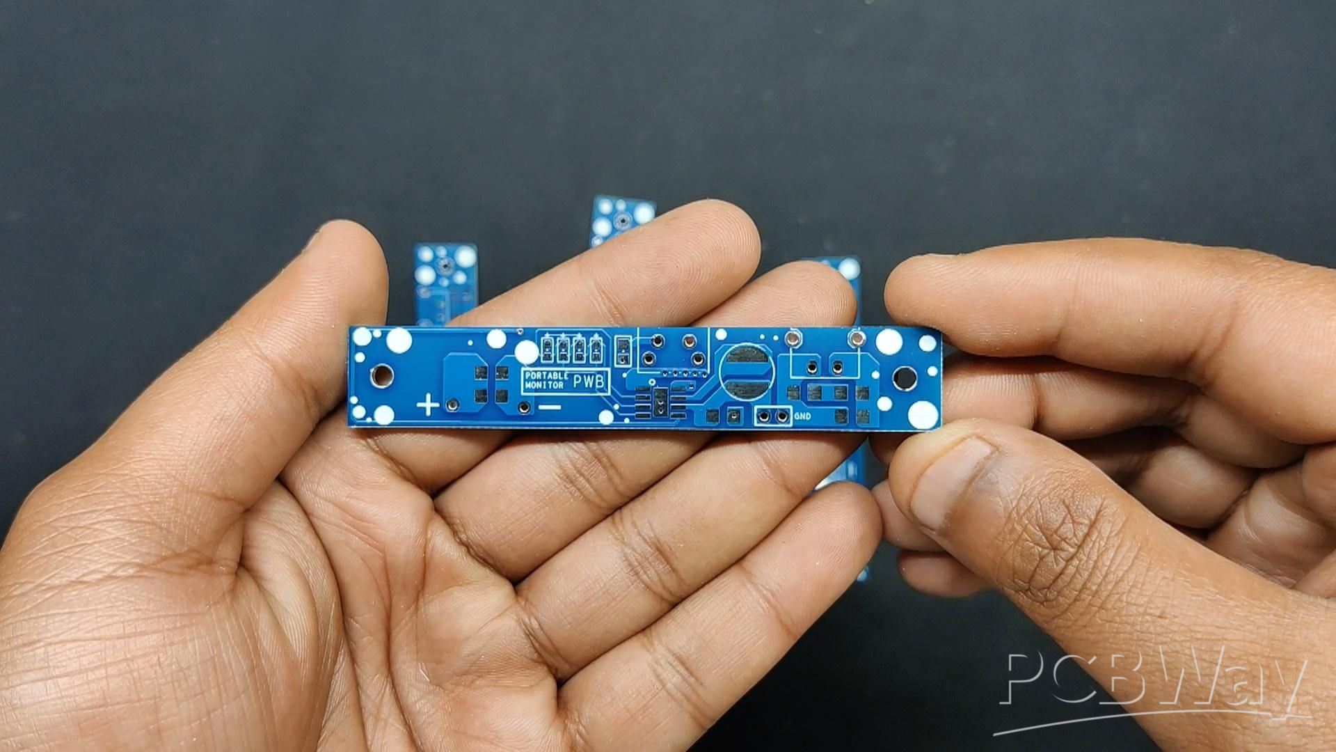
Two Orders were placed, one for the button board, which we selected to be made in Purple Solder mask with white silkscreen, and a Power Board order was placed for Blue soldermask with white silkscreen.
After placing the order, PCBs arrived within a week, which was super fast, and the quality of the boards was also high.
Over the past ten years, PCBWay has built a strong reputation for providing reliable PCB manufacturing and assembly services, becoming a go-to choice for engineers and makers worldwide.
Honestly, if you’re making custom PCBs and not checking out PCBWay, you’re just making things harder for yourself. They also offer CNC machining and 3D printing services
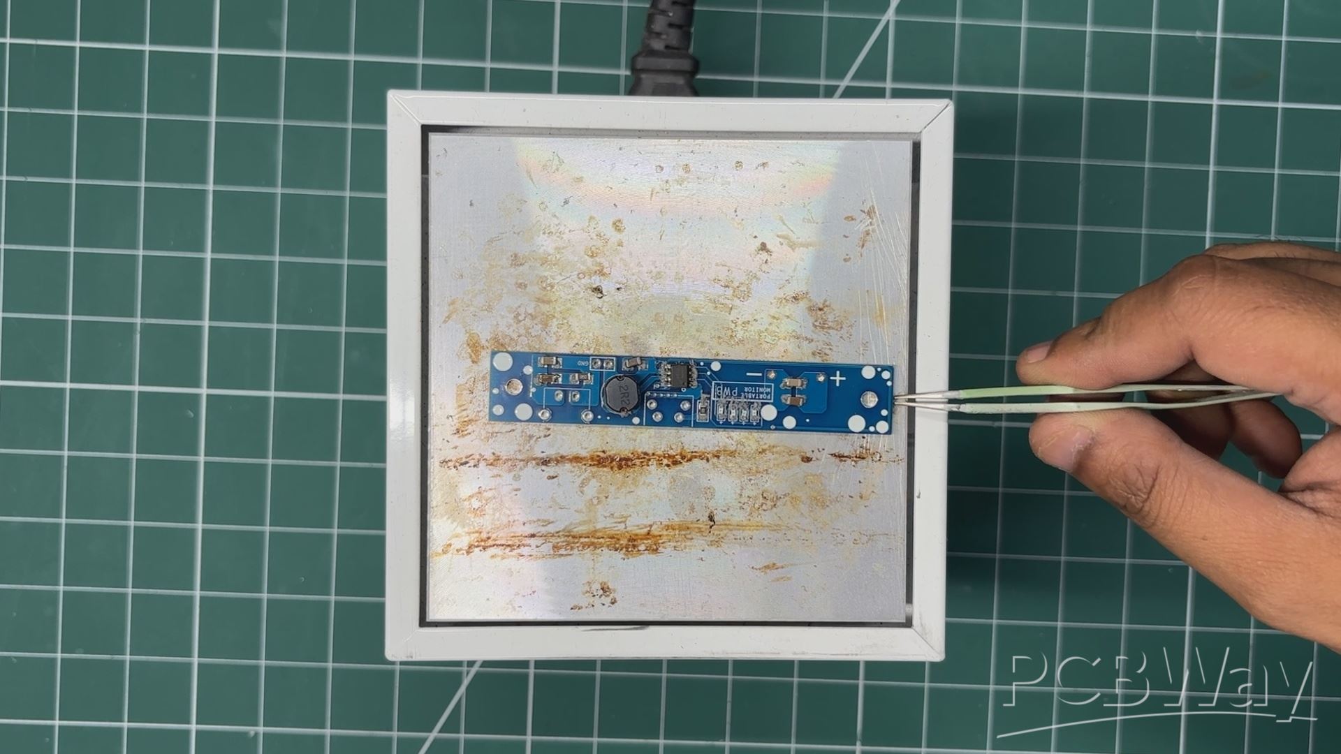
POWER BOARD ASSEMBLY PROCESS
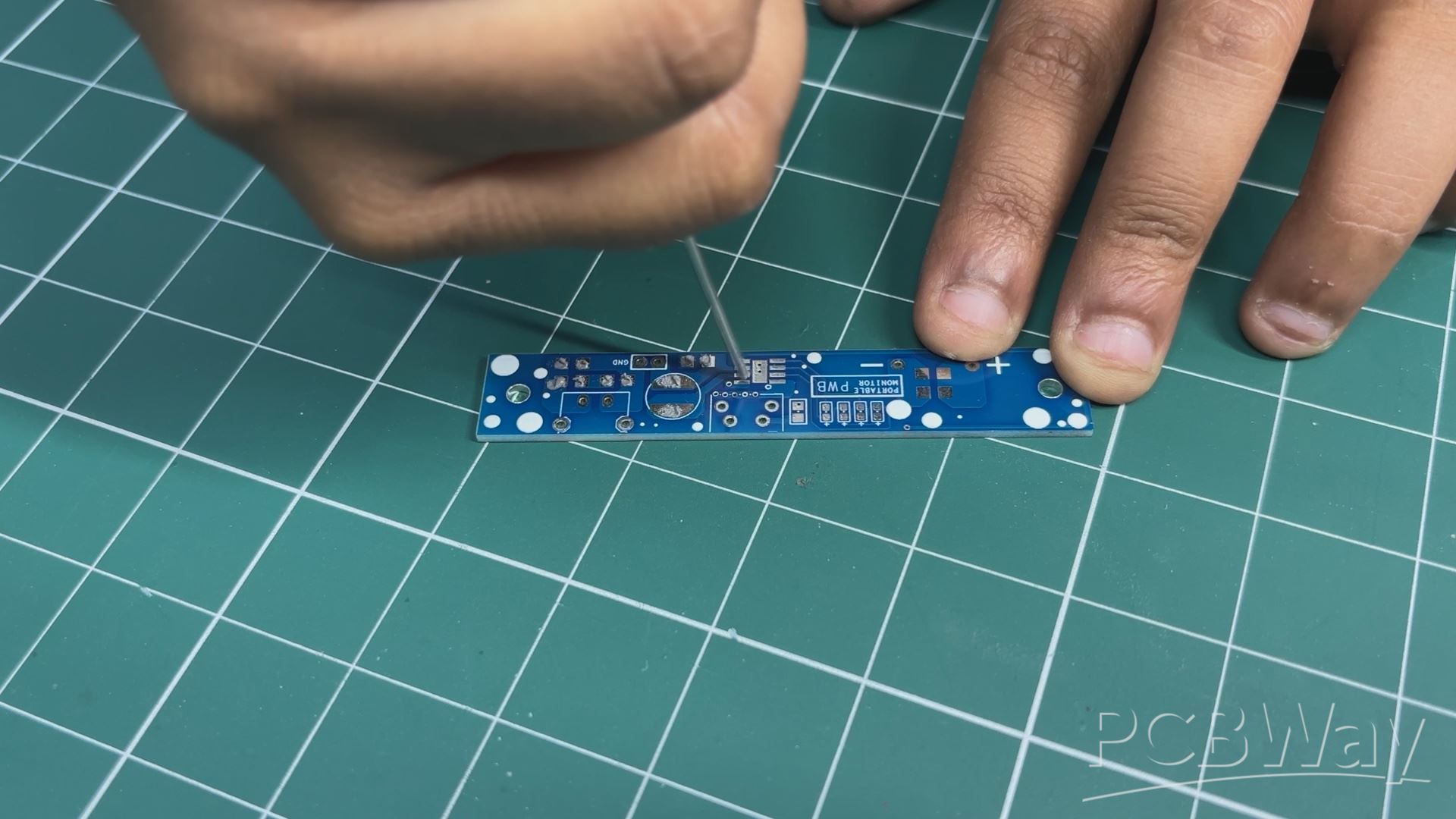
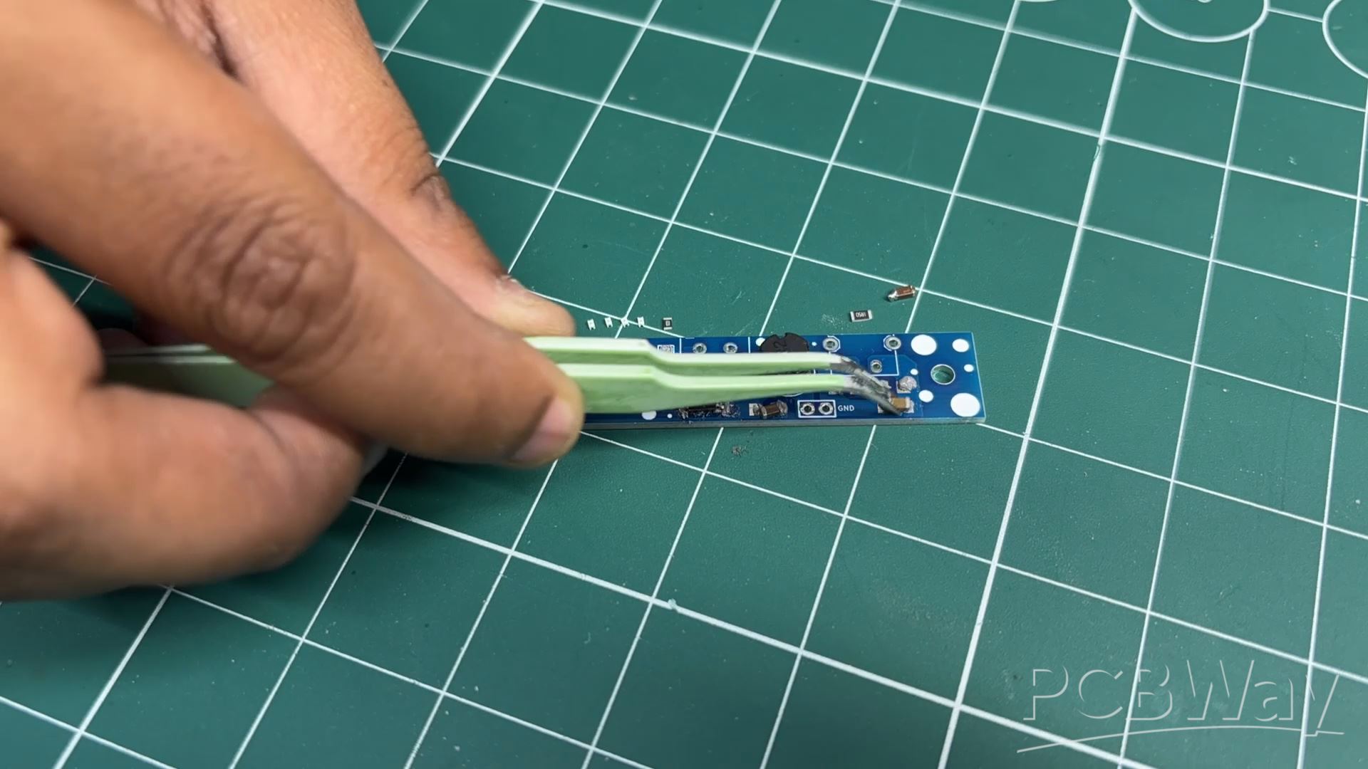
For the assembly process of this PCB, we use a solder paste dispensing syringe. We apply solder paste to each component pad to begin the Main Circuit Assembly process. Here, we are utilizing Sn/Pb 63/37 solder paste, which has a melting temperature of 190 °C.
Next, we pick each SMD component and place it in its correct location.
All of the components are then permanently bound to their pads when the entire circuit is set on the reflow hotplate, which heats the PCB to the solder paste melting temperature.
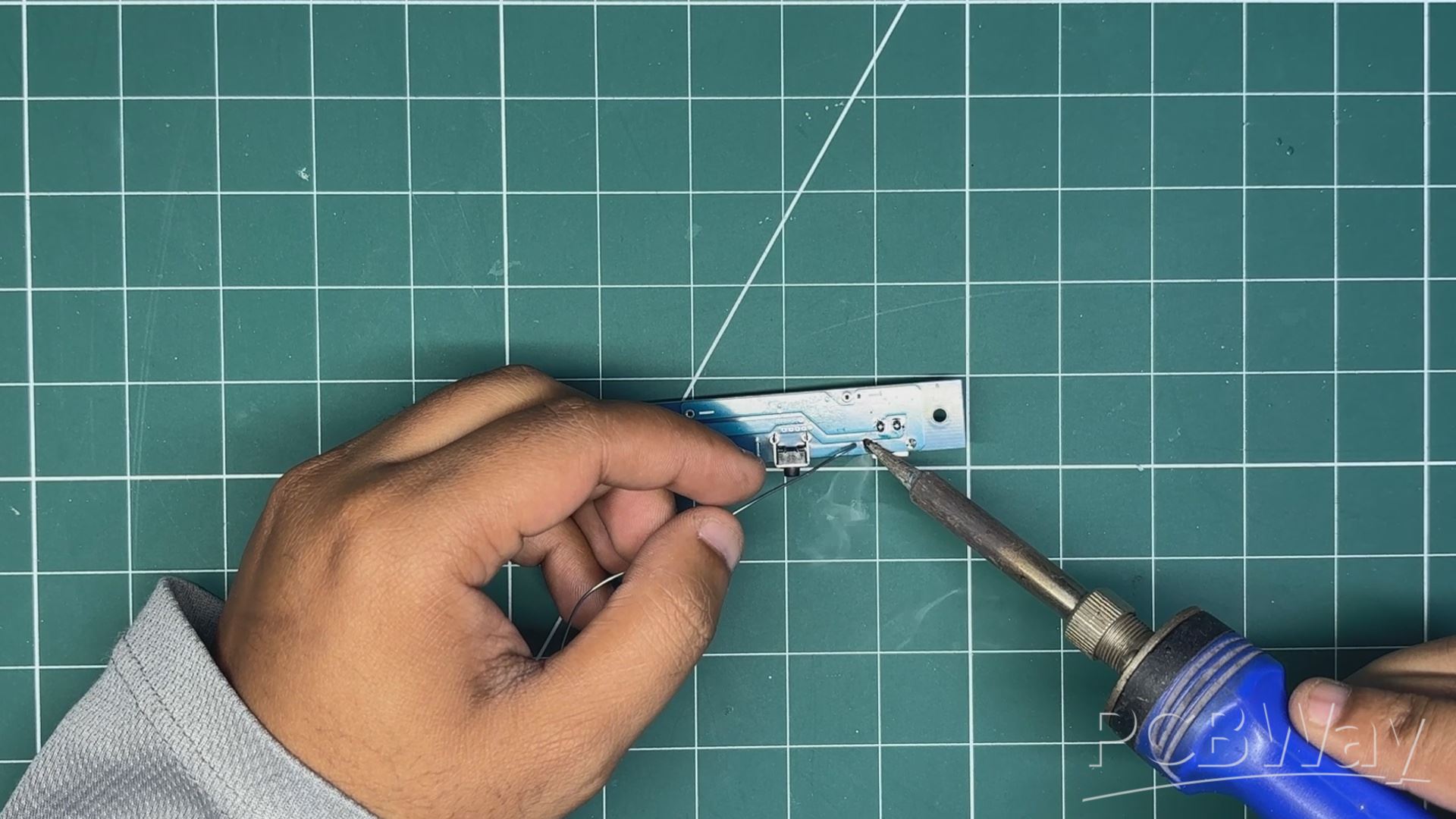
Next, we positioned every THT component, including the Type C port and the vertical push button, in their proper location. We place the Type C Port on the top side, but flip the position of the push button and place it on the bottom side. Using a soldering iron, both components are soldered in their position.
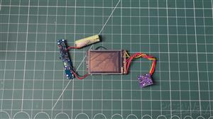
POWER SOURCE
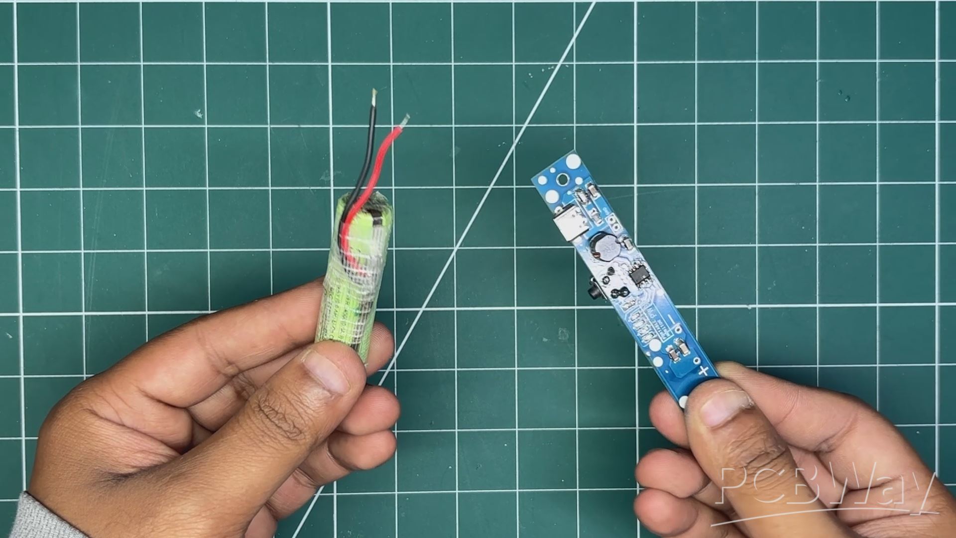
For the power source of this project, we are using a lithium-ion cell, the 14500 form factor 3.7V 600mAh Li-ion cell, to be precise, which comes with a pre-installed PCM circuit. This PCM circuit protects the cell from overcharge and over-discharge, and it even provides short-circuit protection.
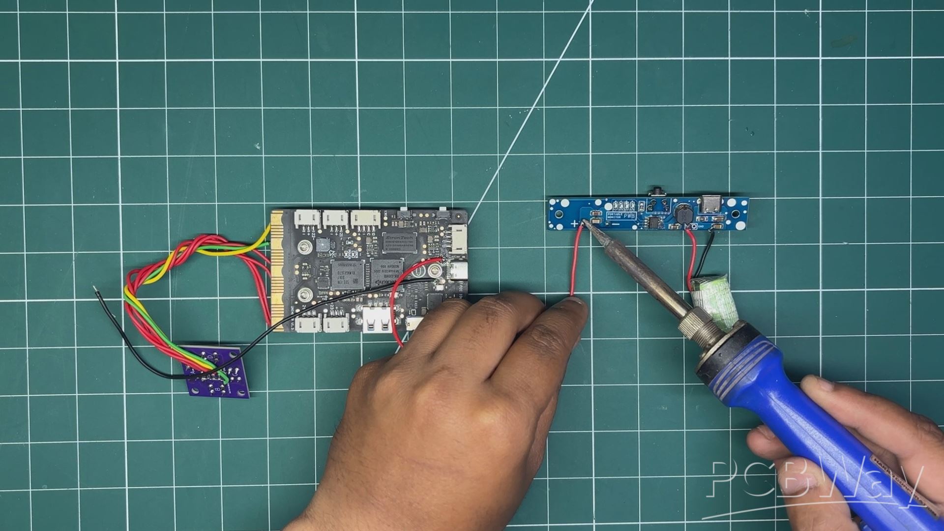
The cell’s B+ and B- are soldered to our power management board’s battery terminals using a soldering iron.
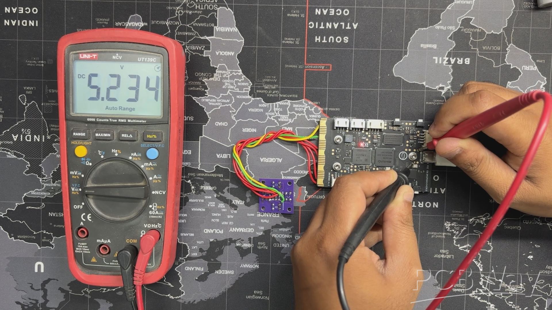
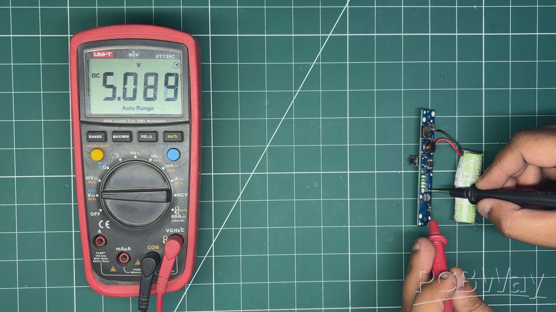
To test the setup, I used a multimeter, pressed the vertical button which turns ON the circuit, and we can see the indicator LED light up.
Using the multimeter, we can check the output voltage of the circuit, which measured a stable 5V, meaning the setup is working.
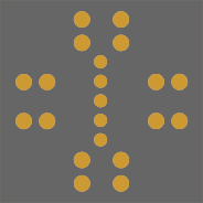
PCB DESIGN- BUTTON BOARD
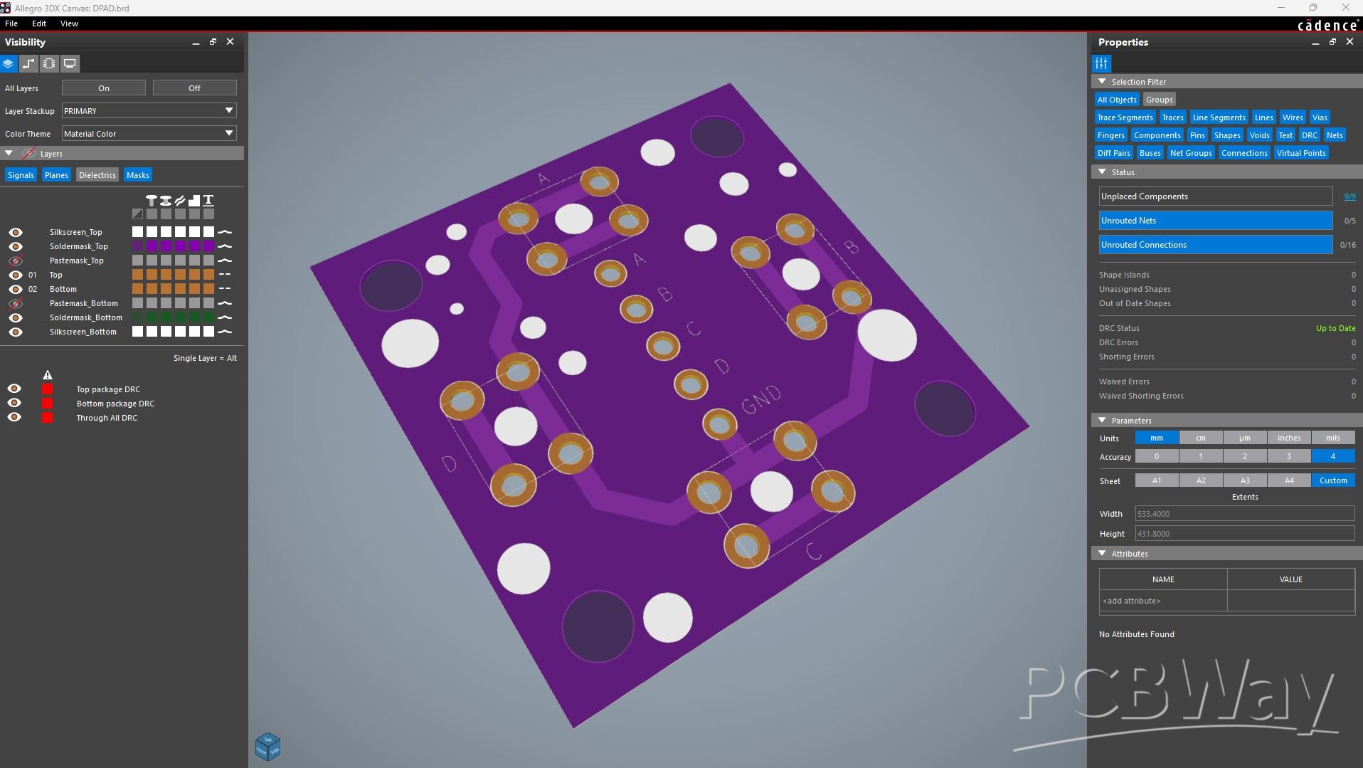
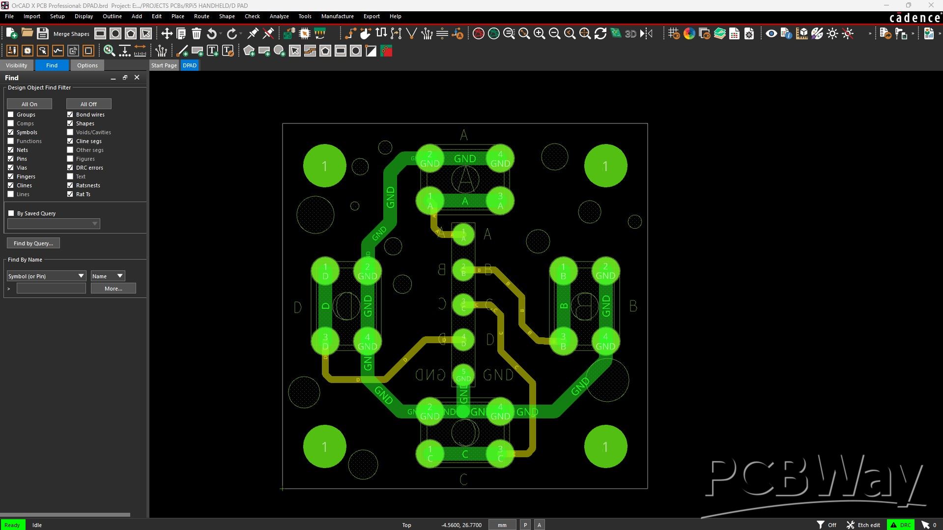
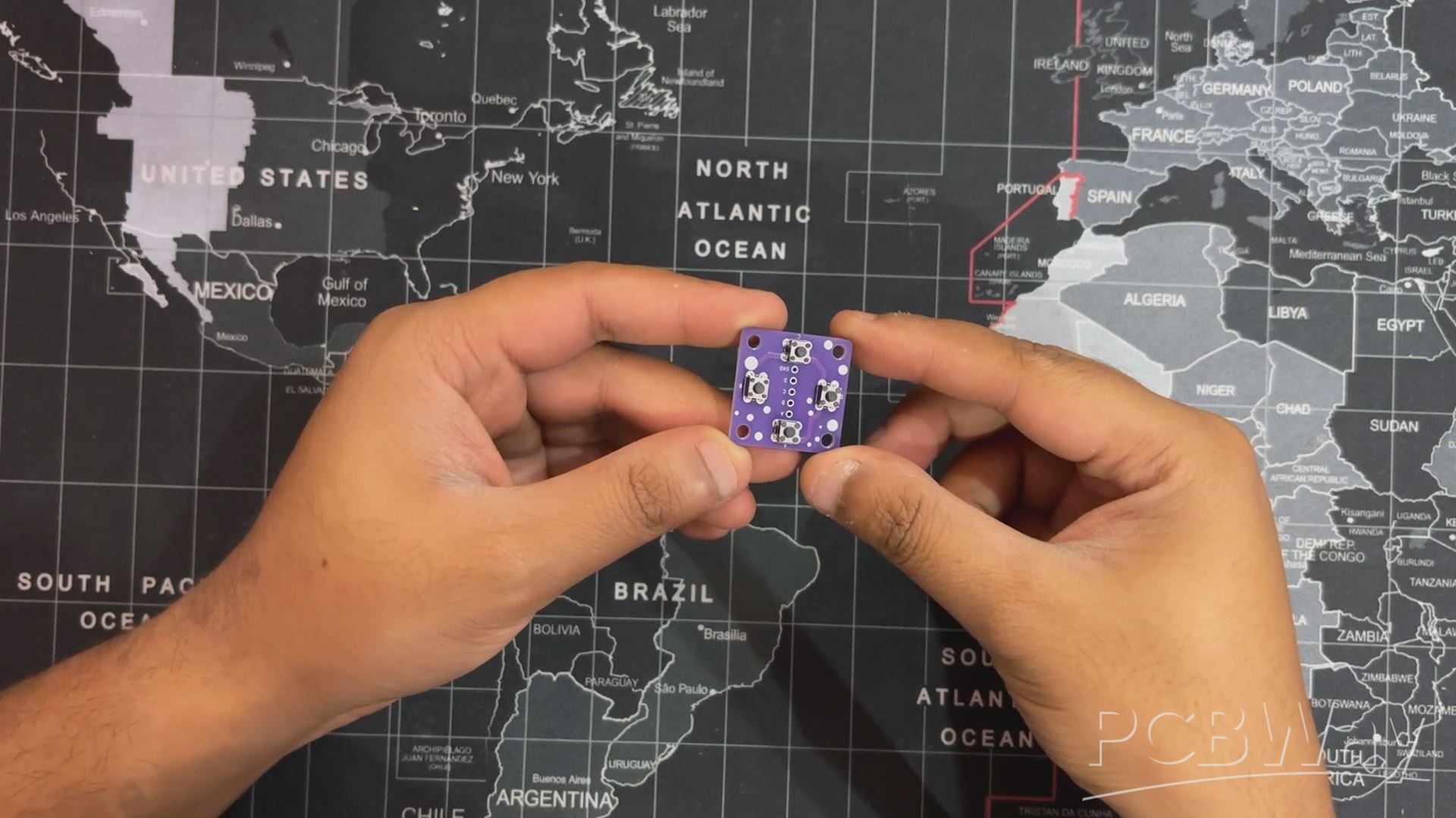
Here’s the second PCB we used in our project, the Button Board.
Here, we have added four 4×4mm push buttons on a 20×20mm board. The placement of each button and the mounting holes are all positioned according to the 3D model.
A CON5 connector is also added. The first pin is connected to GND, and the remaining four terminals are connected to each button pin. Through this connector, we will later pair the UNIHIKER M10 with our button board.
BTW, we are reusing this PCB from a previous project, which you can check out from the link below.
https://www.hackster.io/Arnov_Sharma_makes/hitpad-6182e1
BUTTON BOARD ASSEMBLY PROCESS
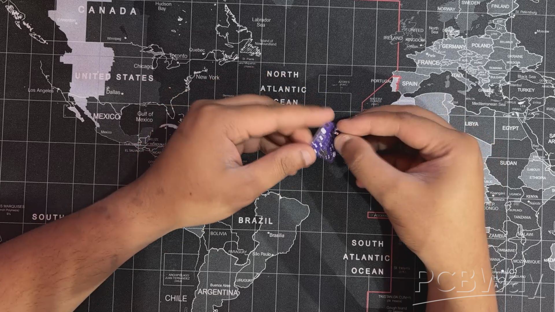
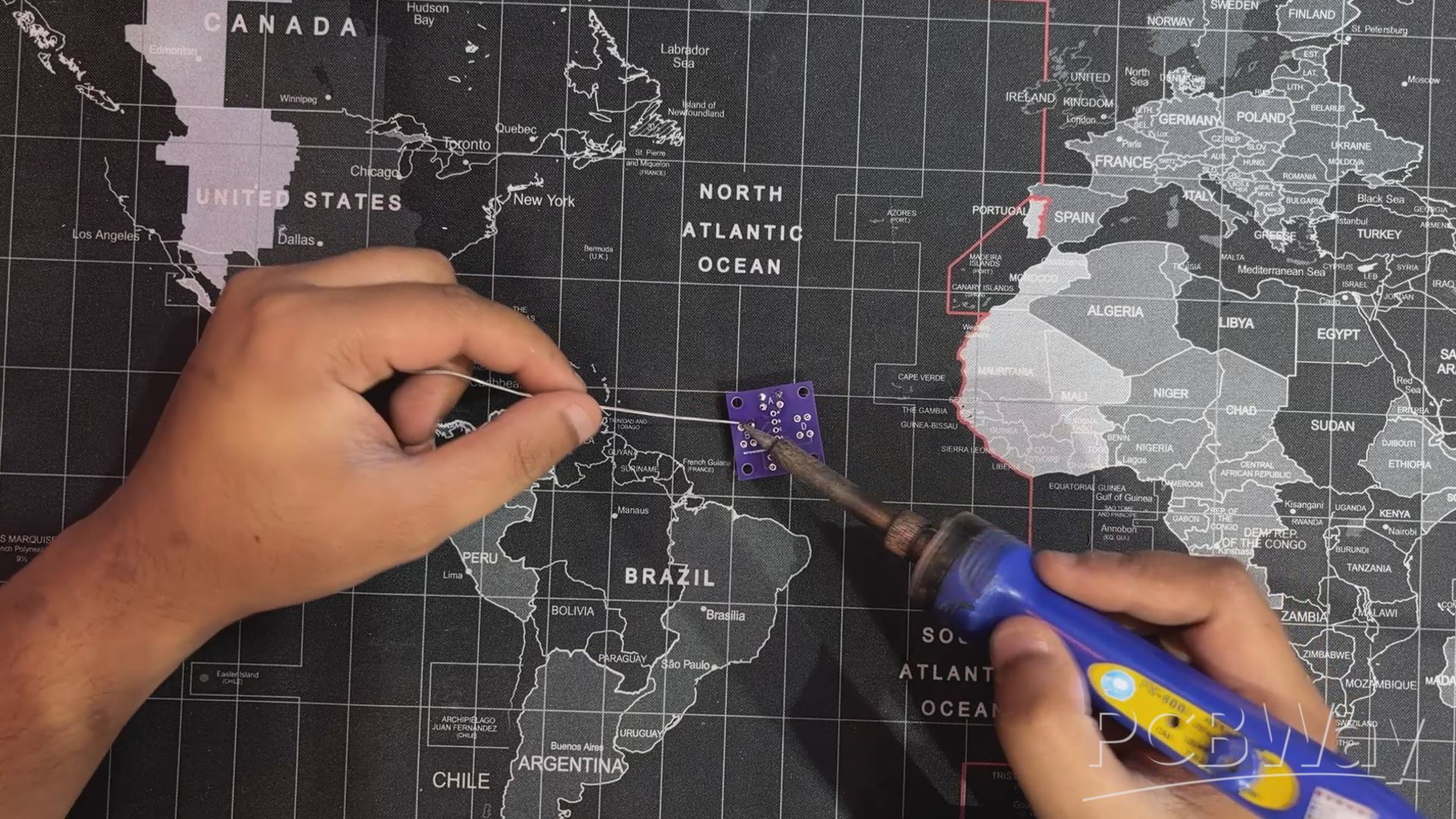
The button board assembly was pretty straightforward.
We placed all four push buttons in their positions, flipped the board over, and then used a soldering iron to solder all the leads of the push buttons.
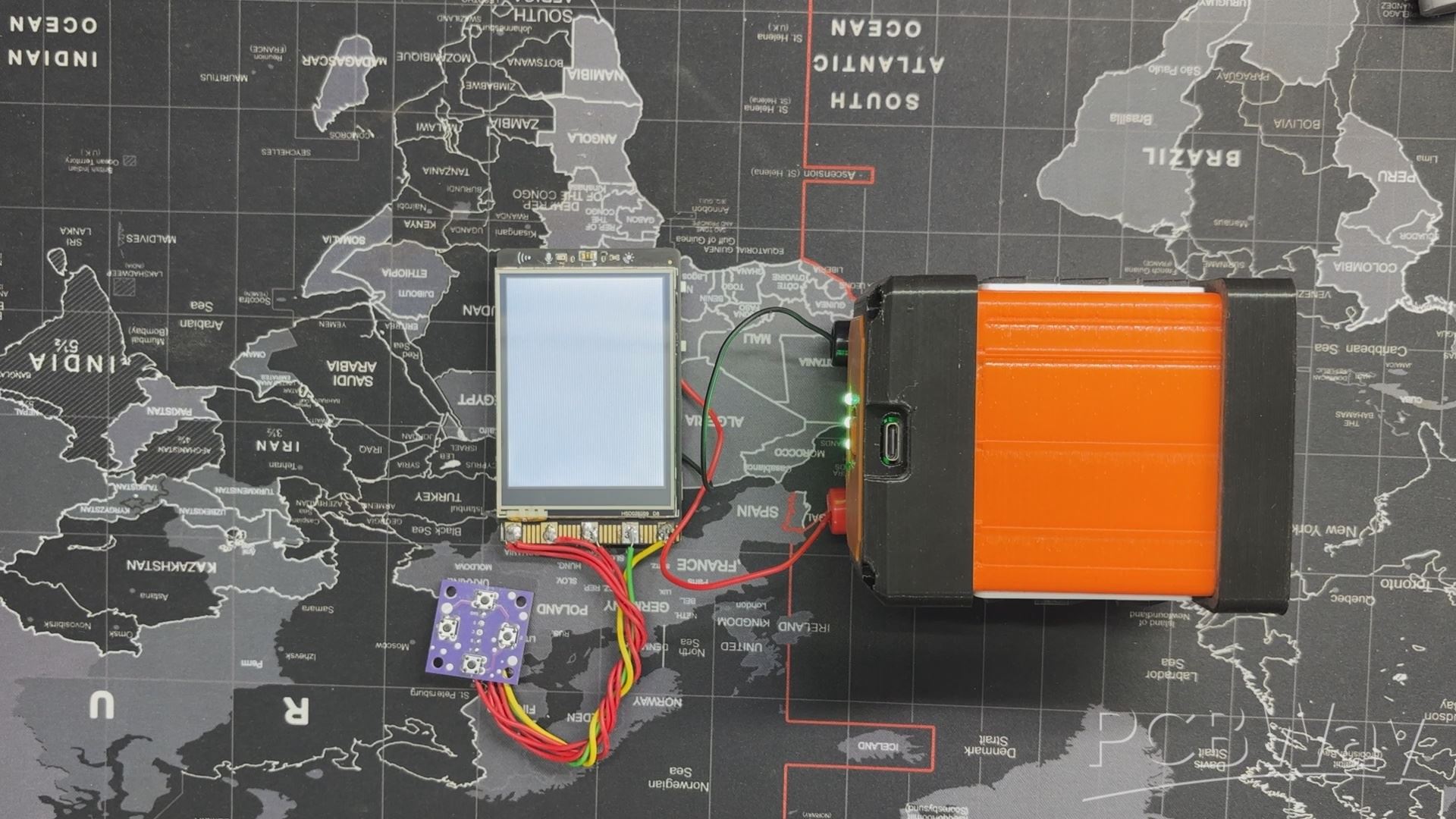
ELECTRONICS SETUP
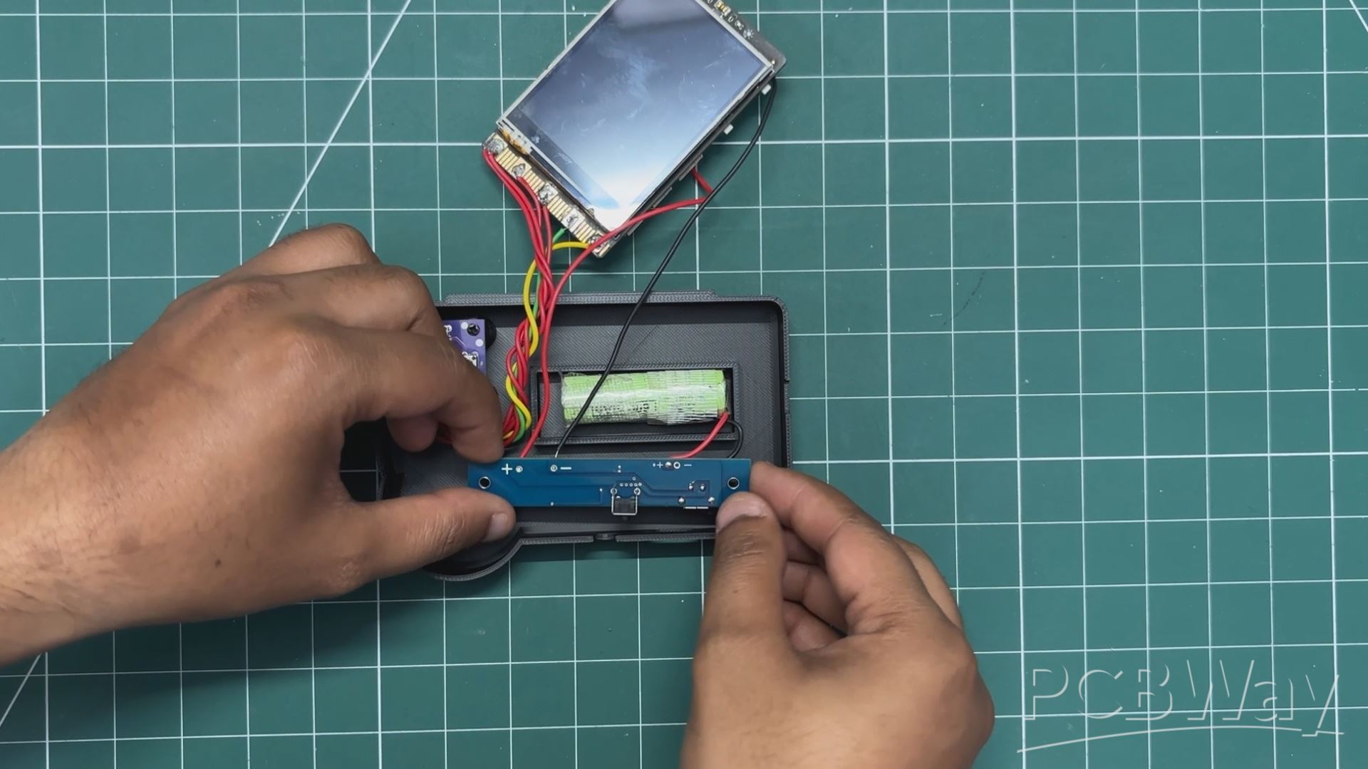
The electronic setup of this project consists of the UNIHIKER M10 paired with the button board in the following order:
Button A is connected to P3 of the UNIHIKER.Button B is connected to P0 of the UNIHIKER.Button C is connected to P1.Button D is connected to P2.
We have also used the onboard buzzer, which is paired with P26.
Next, we paired the power board’s 5V and GND terminals with the 5V and GND of the UNIHIKER using a pair of connecting wires.
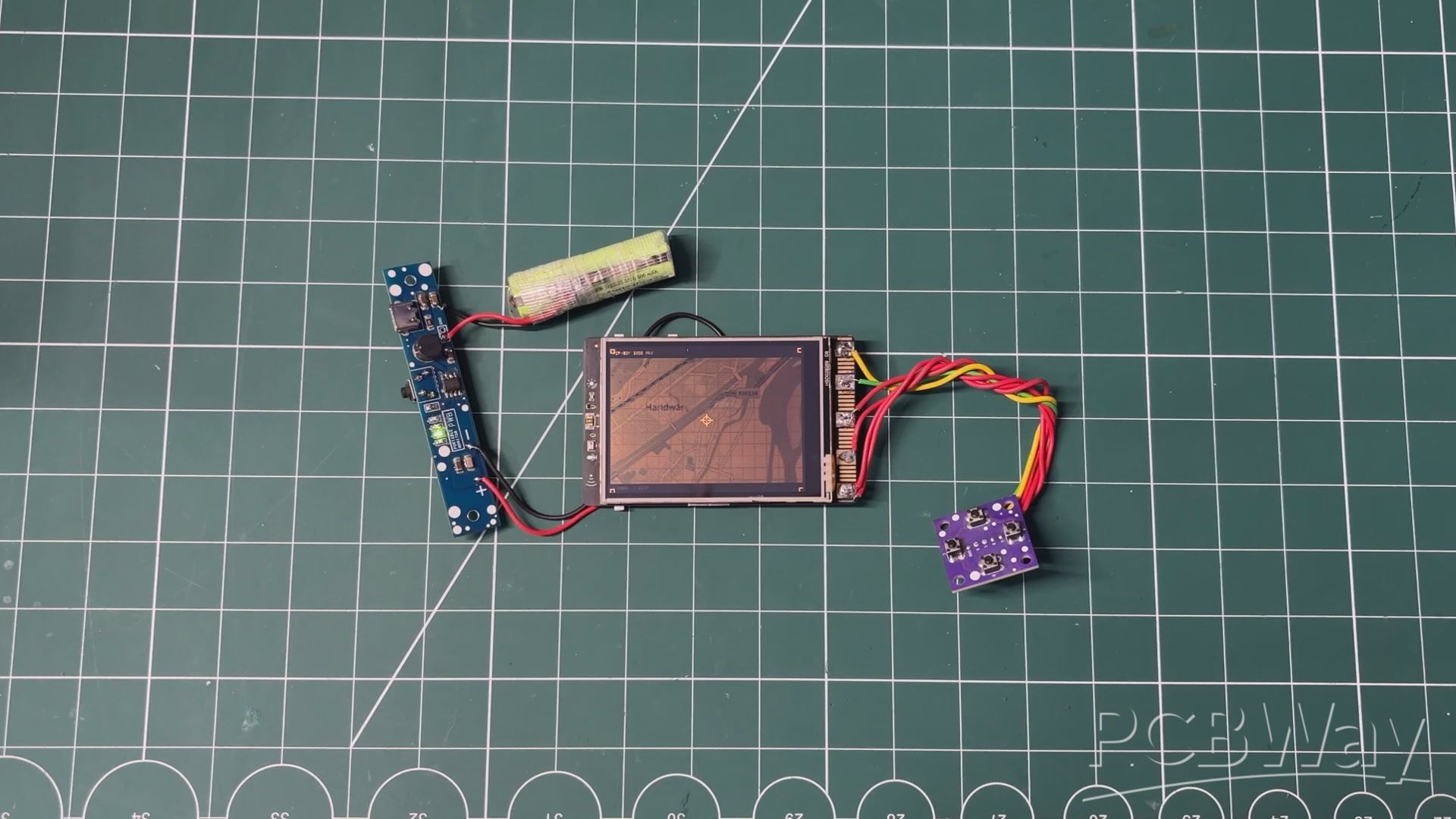
By pressing the vertical push button, the setup turns ON, and the UNIHIKER screen lights up, signaling that the setup is working.
BODY ASSEMBLY PROCESS
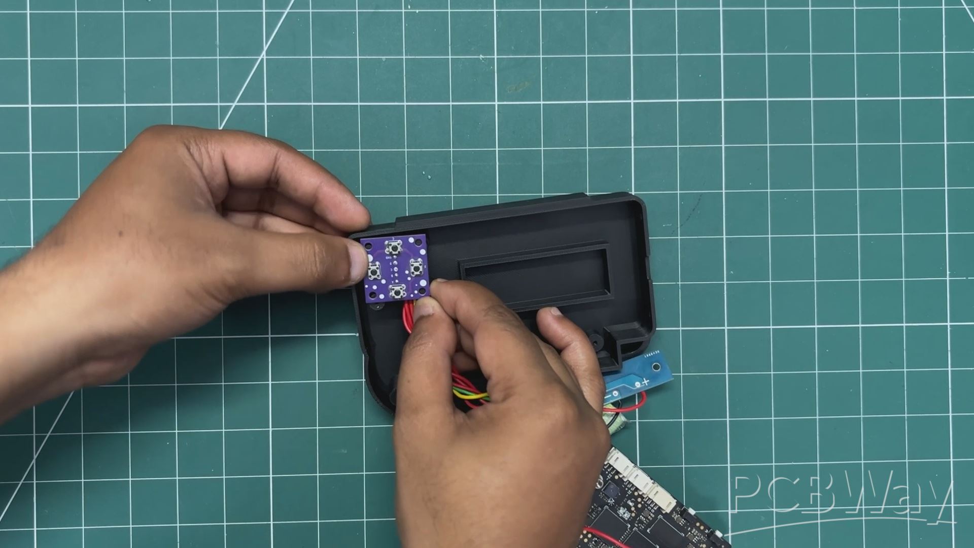
We now begin the assembly process, which starts with placing the button board over the four screw bosses. Then, we secure it using four M2 screws.
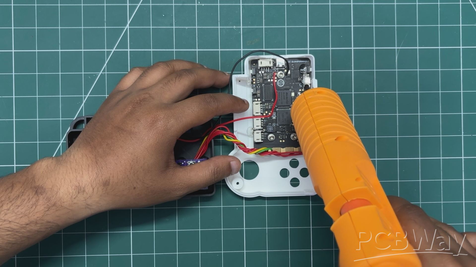
Next, the lithium cell is placed in the lower body, where we have modeled a battery holder. The circuit is also placed in its position over two screw bosses and tightened in place using two M2 screws. We use a little hot glue to keep the cell intact and in place.
We use superglue to attach the aesthetic part we modeled and place it over the front body. We apply superglue to the front side, place the aesthetic part, and secure it in position.
The UNIHIKER M10 is positioned from the inside of the front body. We use hot glue to keep it securely in place.
The 3D-printed buttons are added in their place from the inside of the front body. Then, both the front and back bodies are put together and secured using four M2 screws.
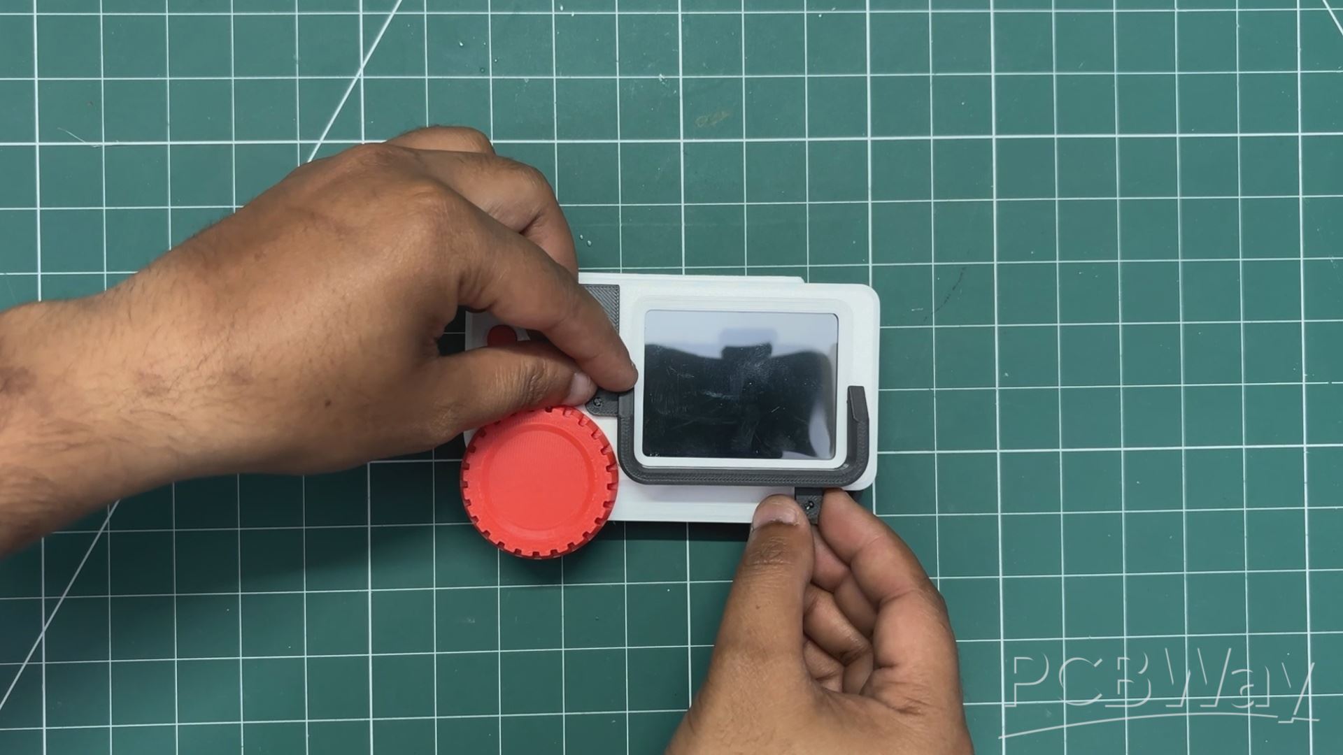
Next, the knob part is added in place on the front side of the device. This knob serves only an aesthetic purpose and is not functional.
From the front side, we place the shade part in position and mount it using two M2 screws.
Assembly has been completed.
WEARABLE STRAP
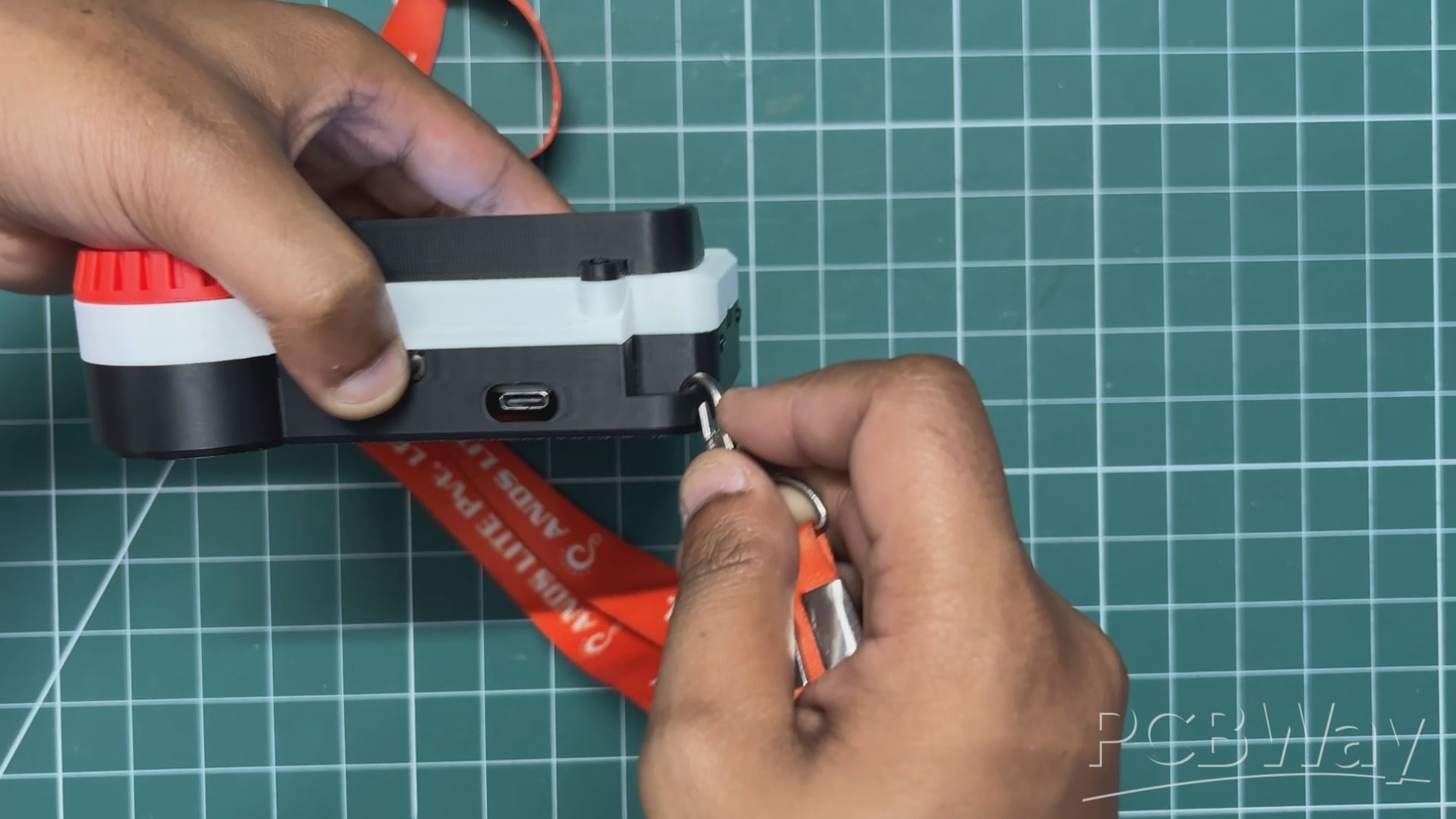
To make the device wearable, I attached an ID card strap so it can be carried more easily.
The strap hook is clipped onto a custom part I designed on the left side of the enclosure. Once attached, the device can be worn just like an ID card.
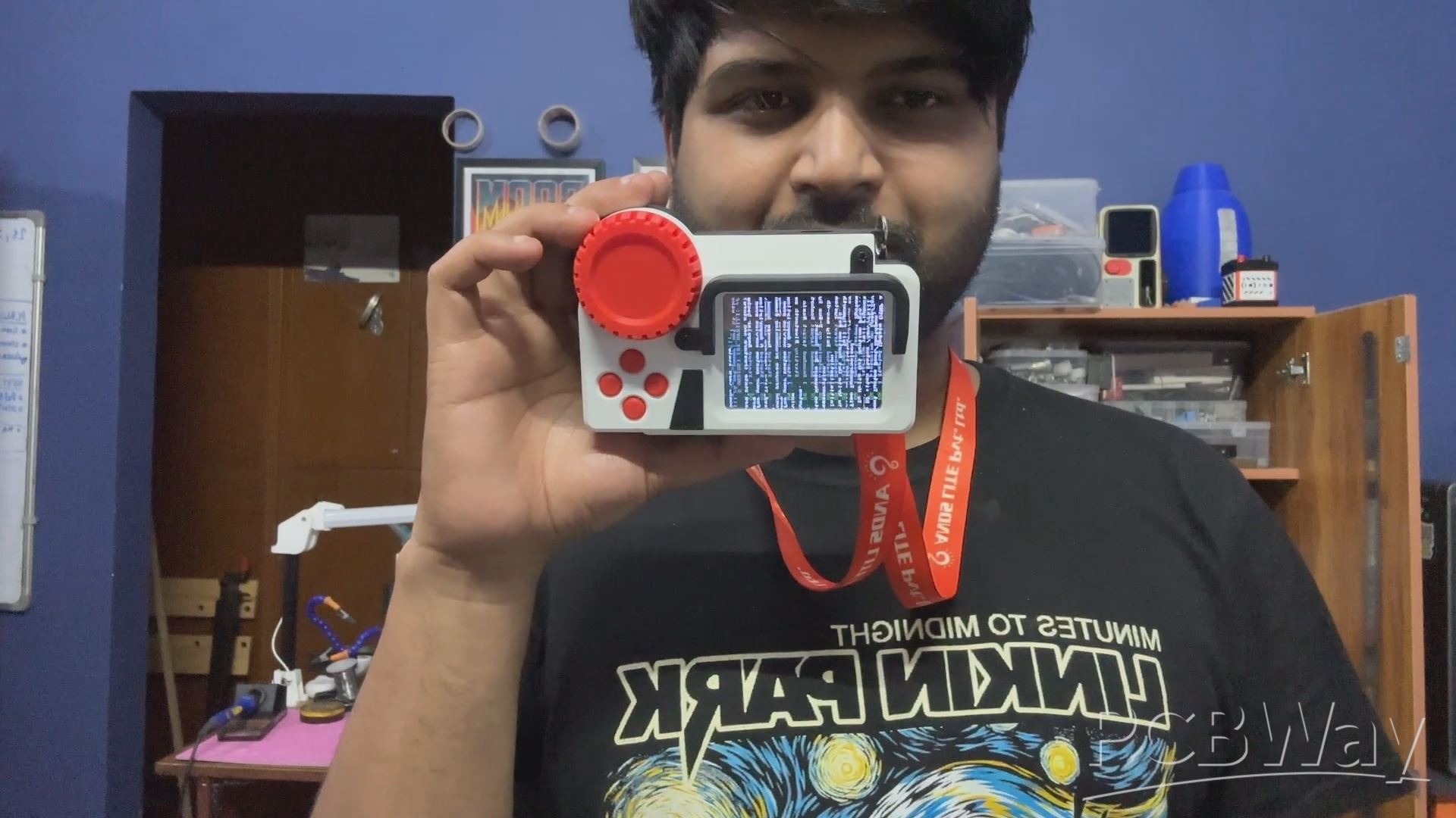
RESULT
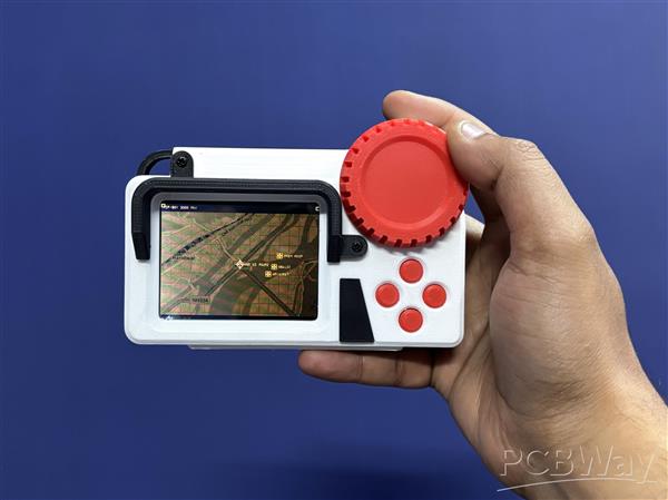
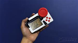
Here’s the end result of this project: PathFinder, my DIY digital map device that helps fellow travelers find their path. It’s basically a map inside a screen, loaded without Wi-Fi or any internet connection. Using the directional pad, we can easily navigate the map.
The map is designed to look like the one from Fallout: New Vegas, with the amber tint, but it shows my town, which is pretty cool.
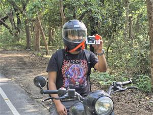
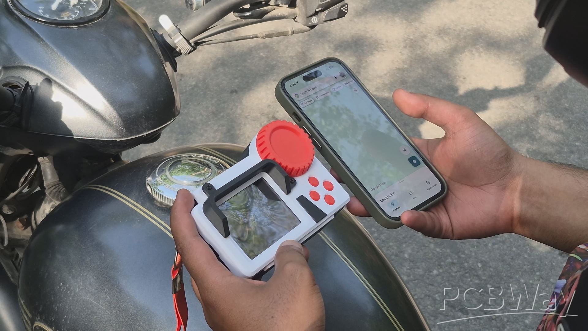
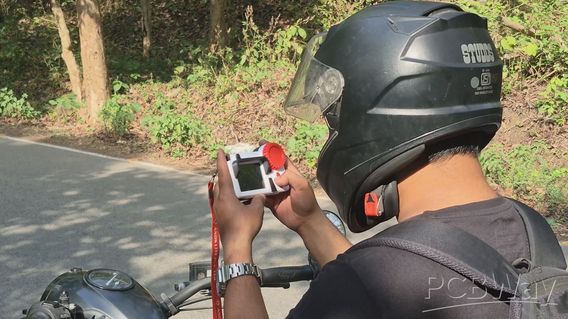
To test the device in real life, I took my motorcycle out and went to an area I hadn’t been to before. I tried navigating using the PathFinder, and it worked quite well.
I followed the map, went onto a road in the middle of nowhere, actually in the middle of a jungle, navigated through it, and eventually got back to a familiar highway.
CONCLUSION

This map works, and it works quite well, but I ran into a few issues during field testing.
The most annoying one was the display. The backlight of the UNIHIKER display is quite dim, making it difficult to read under direct sunlight. I even designed a shade for it, but that didn’t help much. On top of that, the display has a shiny, reflective layer for the touchscreen, which makes visibility even worse outdoors.
Another limitation is the map size. Right now, the map covers a limited area of around 2000×2000 pixels. This can be increased by modifying the size in map.py, but doing so makes the code heavier. So, I need to figure out a way to scale the map efficiently without significantly increasing the code size.
I also realized that this device might be more practical if mounted on my motorcycle instead of being worn like a badge.
In that setup, I could expand its functionality by adding temperature sensors, video recording, or even some AI features like tracking vehicles ahead. It could even include a Bluetooth speaker if mounted on the bike; possibilities are unlimited.
For version 2 of this project, I’ll be working on fixing basic issues first and maybe even taking it along on a ride somewhere.
Special thanks if you made it this far, and I will be back with a new project real soon!
Peace.

PathFinder
*PCBWay community is a sharing platform. We are not responsible for any design issues and parameter issues (board thickness, surface finish, etc.) you choose.


Raspberry Pi 5 7 Inch Touch Screen IPS 1024x600 HD LCD HDMI-compatible Display for RPI 4B 3B+ OPI 5 AIDA64 PC Secondary Screen(Without Speaker)
BUY NOW


- Comments(1)
- Likes(1)
More by Arnov Arnov sharma
-
 DIY XBOX Controller
Greetings everyone, and welcome back. Here's something fun and custom.This is my version of an Xbox ...
DIY XBOX Controller
Greetings everyone, and welcome back. Here's something fun and custom.This is my version of an Xbox ...
-
 Pocket SNES
Greetings everyone, and welcome back! Today, I’ve got something fun and tiny to share—the Pocket SNE...
Pocket SNES
Greetings everyone, and welcome back! Today, I’ve got something fun and tiny to share—the Pocket SNE...
-
 Batocera Arcade Box
Greetings everyone and welcome back, Here's something. Fun and nostalgic. Right now, we are using ou...
Batocera Arcade Box
Greetings everyone and welcome back, Here's something. Fun and nostalgic. Right now, we are using ou...
-
 64x32 Matrix Panel Setup with PICO 2
Greetings everyone and welcome back.So here's something fun and useful: a Raspberry Pi Pico 2-powere...
64x32 Matrix Panel Setup with PICO 2
Greetings everyone and welcome back.So here's something fun and useful: a Raspberry Pi Pico 2-powere...
-
 Portable Air Quality Meter
Hello everyone, and welcome back! Today, I have something incredibly useful for you—a Portable Air Q...
Portable Air Quality Meter
Hello everyone, and welcome back! Today, I have something incredibly useful for you—a Portable Air Q...
-
 WALKPi PCB Version
Greetings everyone and welcome back, This is the WalkPi, a homebrew audio player that plays music fr...
WALKPi PCB Version
Greetings everyone and welcome back, This is the WalkPi, a homebrew audio player that plays music fr...
-
 Delete Button XL
Greetings everyone and welcome back, and here's something fun and useful.In essence, the Delete Butt...
Delete Button XL
Greetings everyone and welcome back, and here's something fun and useful.In essence, the Delete Butt...
-
 Arduino Retro Game Controller
Greetings everyone and welcome back. Here's something fun.The Arduino Retro Game Controller was buil...
Arduino Retro Game Controller
Greetings everyone and welcome back. Here's something fun.The Arduino Retro Game Controller was buil...
-
 Super Power Buck Converter
Greetings everyone and welcome back!Here's something powerful, The SUPER POWER BUCK CONVERTER BOARD ...
Super Power Buck Converter
Greetings everyone and welcome back!Here's something powerful, The SUPER POWER BUCK CONVERTER BOARD ...
-
 Pocket Temp Meter
Greetings and welcome back.So here's something portable and useful: the Pocket TEMP Meter project.As...
Pocket Temp Meter
Greetings and welcome back.So here's something portable and useful: the Pocket TEMP Meter project.As...
-
 Pico Powered DC Fan Driver
Hello everyone and welcome back.So here's something cool: a 5V to 12V DC motor driver based around a...
Pico Powered DC Fan Driver
Hello everyone and welcome back.So here's something cool: a 5V to 12V DC motor driver based around a...
-
 Mini Solar Light Project with a Twist
Greetings.This is the Cube Light, a Small and compact cube-shaped emergency solar light that boasts ...
Mini Solar Light Project with a Twist
Greetings.This is the Cube Light, a Small and compact cube-shaped emergency solar light that boasts ...
-
 PALPi V5 Handheld Retro Game Console
Hey, Guys what's up?So this is PALPi which is a Raspberry Pi Zero W Based Handheld Retro Game Consol...
PALPi V5 Handheld Retro Game Console
Hey, Guys what's up?So this is PALPi which is a Raspberry Pi Zero W Based Handheld Retro Game Consol...
-
 DIY Thermometer with TTGO T Display and DS18B20
Greetings.So this is the DIY Thermometer made entirely from scratch using a TTGO T display board and...
DIY Thermometer with TTGO T Display and DS18B20
Greetings.So this is the DIY Thermometer made entirely from scratch using a TTGO T display board and...
-
 Motion Trigger Circuit with and without Microcontroller
GreetingsHere's a tutorial on how to use an HC-SR505 PIR Module with and without a microcontroller t...
Motion Trigger Circuit with and without Microcontroller
GreetingsHere's a tutorial on how to use an HC-SR505 PIR Module with and without a microcontroller t...
-
 Motor Driver Board Atmega328PU and HC01
Hey, what's up folks here's something super cool and useful if you're making a basic Robot Setup, A ...
Motor Driver Board Atmega328PU and HC01
Hey, what's up folks here's something super cool and useful if you're making a basic Robot Setup, A ...
-
 Power Block
Hey Everyone what's up!So this is Power block, a DIY UPS that can be used to power a bunch of 5V Ope...
Power Block
Hey Everyone what's up!So this is Power block, a DIY UPS that can be used to power a bunch of 5V Ope...
-
 Goku PCB Badge V2
Hey everyone what's up!So here's something SUPER cool, A PCB Board themed after Goku from Dragon Bal...
Goku PCB Badge V2
Hey everyone what's up!So here's something SUPER cool, A PCB Board themed after Goku from Dragon Bal...
-
Programmable Mist Maker - XIAO / QT PY Extension
217 0 0 -
RadioHAT - Raspberry Pi radio development platform
244 0 1 -
-
-
-
-
ARPS-2 – Arduino-Compatible Robot Project Shield for Arduino UNO
2795 0 5 -
A Compact Charging Breakout Board For Waveshare ESP32-C3
3299 3 8 -
AI-driven LoRa & LLM-enabled Kiosk & Food Delivery System
3575 2 2


