


Morten Frederiksen
DENMARK • + Follow


Components
|
|
Raspberry Pi PICO W |
x 1 | |
|
|
RT314005TE Connectivity
|
x 1 | |
|
|
SHT31-DIS-B2.5KSSensirion AG
|
x 1 |
Tools, APP Software Used etc.

|
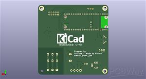
KiCad 9.0 |
|

|
arduino IDEArduino
|
Description
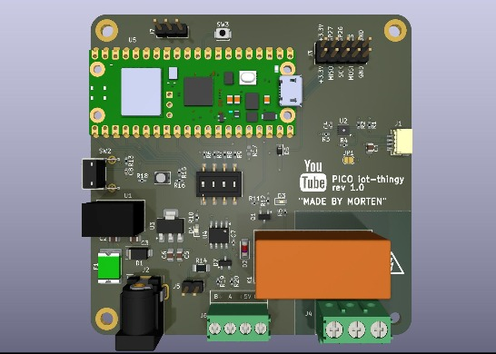
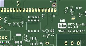
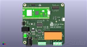
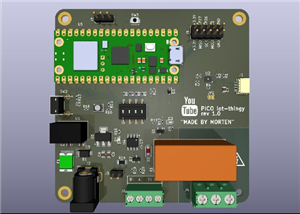
PICO-RS485
The main feautures for this board are:
- Raspberry Pi Pico (W) or any other variant
- RS485 / MOD-bus interface
- SHT31-DIS high precision temperature and humidity sensor
- QWIIC connector
- Power relay (230V - 16A)
- Wide range input voltage +8V to 24V DC
- Reset Button
- User Button
- User RGB LED
- 2x5 pin SPI bus expansion header
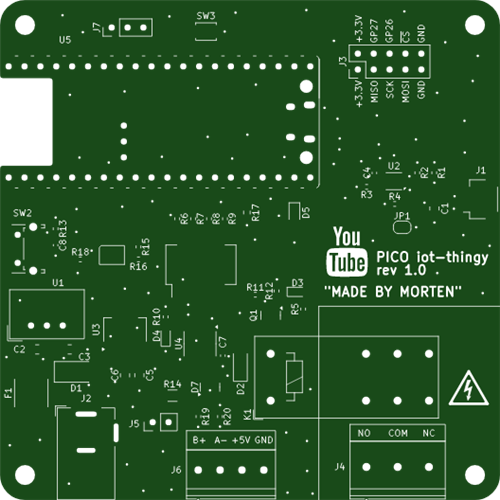
For the mechanical side of things we have:
- 4 x 3.2mm mounting holes
- Size 80x80mm
- 4 layer board design
Schematic and Layout
Schematic
PICO-RS485.pdf
Made by Morten Repo:
https://github.com/mortens-lab
Sep 04,2025
1,685 views
PICO-RS485
General IoT testboard based on a Raspberry Pi Pico (W) - features RS485 interface, power Relay, LEDs plus Temperature and Humidity sensor
1685
4
0
Published: Sep 04,2025
Standard PCB
Download Gerber file 21
BOM(Bill of materials)
Centroid file
PCBWay Donate 10% cost To Author
File Last Updated: 2025/09/04 (GMT+8)
File update record
2025-09-0422:16:20
Centroid file is updated.
2025-09-0422:16:20
Parts List (BOM) is updated.
Only PCB
PCB+Assembly
*PCBWay community is a sharing platform. We are not responsible for any design issues and parameter issues (board thickness, surface finish, etc.) you choose.


Under the
Attribution-ShareAlike (CC BY-SA)
License.


Raspberry Pi 5 7 Inch Touch Screen IPS 1024x600 HD LCD HDMI-compatible Display for RPI 4B 3B+ OPI 5 AIDA64 PC Secondary Screen(Without Speaker)
BUY NOW


- Comments(0)
- Likes(4)
Upload photo
You can only upload 5 files in total. Each file cannot exceed 2MB. Supports JPG, JPEG, GIF, PNG, BMP
0 / 10000
More by Morten Frederiksen
-
 PICO-RS485
The main feautures for this board are:- Raspberry Pi Pico (W) or any other variant- RS485 / MOD-bus ...
PICO-RS485
The main feautures for this board are:- Raspberry Pi Pico (W) or any other variant- RS485 / MOD-bus ...
-
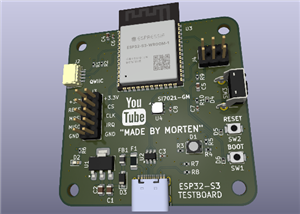 ESP32-S3 Testboard
:Size : 50x50mm4-layer designStack-up:TOP0.196mm prepegIN11.03 coreIN20,196mmBOTIn...
ESP32-S3 Testboard
ESP32-S3 Testboard:Size : 50x50mm4-layer designStack-up:TOP0.196mm prepegIN11.03 coreIN20,196mmBOTIn...
-
 ESP32-C6 Demo-Board
I am working on a demoboard for espressif ESP32-C6. The ESP32-C6-WROOM-1 module is a multiprotocol p...
ESP32-C6 Demo-Board
I am working on a demoboard for espressif ESP32-C6. The ESP32-C6-WROOM-1 module is a multiprotocol p...
-
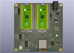 ESP32 + 2 x PICO testboard - evaluation platform
This is a testboard that i did as I wanted a platfor...
ESP32 + 2 x PICO testboard - evaluation platform
ESP32 + 2 x PICO testboard - evaluation platformThis is a testboard that i did as I wanted a platfor...
-
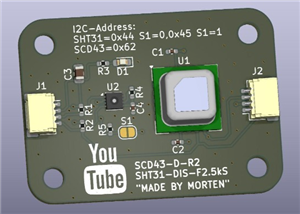 SCD43 + SHT31 testboard
This is a small testboard for the Sensirion:SCD43 (CO2 sensor)SHT31 (Humidity sensor)Size 40x29mm - ...
SCD43 + SHT31 testboard
This is a small testboard for the Sensirion:SCD43 (CO2 sensor)SHT31 (Humidity sensor)Size 40x29mm - ...
-
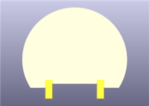 TubeLight - part #3
this is one of the discs that makes up the rail for the TubeLight
TubeLight - part #3
this is one of the discs that makes up the rail for the TubeLight
-
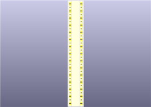 TubeLight - part #2
TubeLight,This is a part of the rail that carries the LED strip
TubeLight - part #2
TubeLight,This is a part of the rail that carries the LED strip
-
 TubeLight - part #1
TubeLight:This is a project that is made up of 3 different PCBs in total. There is the base and the ...
TubeLight - part #1
TubeLight:This is a project that is made up of 3 different PCBs in total. There is the base and the ...
-
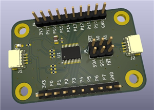 TCAL9539PWR - I2C 16 bit I/O port expander - breakout board
MBOB-TCAL9539PWRThis is a breakout board for the Texas Instruments TCAL9539PWR. This is a 16 bit I/O...
TCAL9539PWR - I2C 16 bit I/O port expander - breakout board
MBOB-TCAL9539PWRThis is a breakout board for the Texas Instruments TCAL9539PWR. This is a 16 bit I/O...
-
 MSPM0C1104S8YCJR (The World's smallest MCU) - Tiny QWIIC connector board
This is a demoboard showcasing the wolrd's smallest MCU on PCB with QWIIC connector and LEDs
MSPM0C1104S8YCJR (The World's smallest MCU) - Tiny QWIIC connector board
This is a demoboard showcasing the wolrd's smallest MCU on PCB with QWIIC connector and LEDs
-
 MSPM0C1104S8YCJR (The World's smallest MCU) - Demoboard
This is a demoboard showcasing the wolrd's smallest MCU
MSPM0C1104S8YCJR (The World's smallest MCU) - Demoboard
This is a demoboard showcasing the wolrd's smallest MCU
-
 LEDstrip 8 x 5.0x5.0mm LEDs (SK6812, WS2812 or similar)
RGB LEDstrip (WS2812B or SK6812)8 x 50x50 LEDsVCC and GND Solder PadsData IN and Data Out solder Pad...
LEDstrip 8 x 5.0x5.0mm LEDs (SK6812, WS2812 or similar)
RGB LEDstrip (WS2812B or SK6812)8 x 50x50 LEDsVCC and GND Solder PadsData IN and Data Out solder Pad...
-
 HUB75 P2.5 RGB matrix display controlled by Raspberry Pi Pico W
Check out on how to make your own shield
HUB75 P2.5 RGB matrix display controlled by Raspberry Pi Pico W
Check out on how to make your own shield
-
 Breakout-16 PCB v1.0
Here is the design for the 4 x 4 breakout boardsYouTube video link:
Breakout-16 PCB v1.0
Here is the design for the 4 x 4 breakout boardsYouTube video link:
-
 Nerd level YouTube Button Version 2 [ESP32, RGB LED Matrix, 3D]
Learn how to make your own advanced YouTube button packed with a lot of cool features, such as speak...
Nerd level YouTube Button Version 2 [ESP32, RGB LED Matrix, 3D]
Learn how to make your own advanced YouTube button packed with a lot of cool features, such as speak...
-
 iot-thing, universal iot development board
iot.thing is a basic module for doing your first iot projects. The module is based on an ESP32-WROOM...
iot-thing, universal iot development board
iot.thing is a basic module for doing your first iot projects. The module is based on an ESP32-WROOM...
You may also like
-
Programmable Mist Maker - XIAO / QT PY Extension
172 0 0 -
RadioHAT - Raspberry Pi radio development platform
182 0 1 -
-
-
-
-
ARPS-2 – Arduino-Compatible Robot Project Shield for Arduino UNO
2767 0 5 -
A Compact Charging Breakout Board For Waveshare ESP32-C3
3275 3 8 -
AI-driven LoRa & LLM-enabled Kiosk & Food Delivery System
3530 2 2


