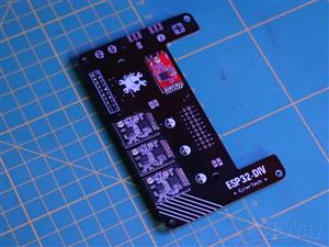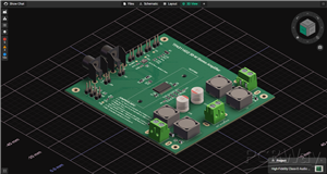



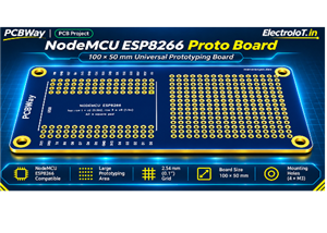
NodeMCU ESP8266 Proto Board 100 x 50 mm
NodeMCU ESP8266 Proto Board – 100 × 50 mm Universal Prototyping PCB
Project Overview
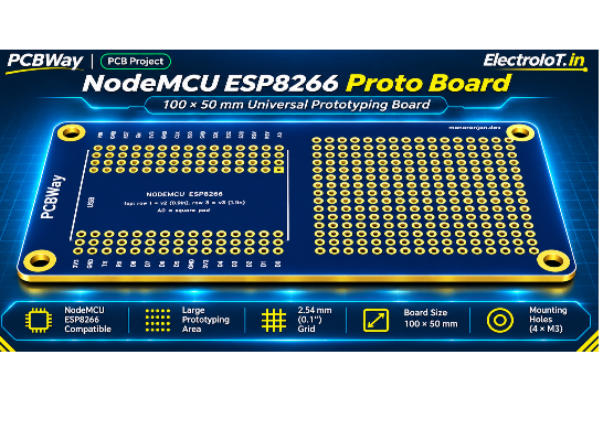
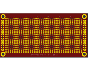
The NodeMCU ESP8266 Proto Board is a universal prototyping PCB designed for NodeMCU ESP8266 development boards. It supports both the common NodeMCU V2 (0.9-inch pin spacing) and V3 / LoLin (1.1-inch pin spacing) module layouts.
The board combines a dedicated NodeMCU mounting area with a large universal solderable prototyping grid, making it suitable for building Wi-Fi-enabled electronics, IoT devices, smart-home controllers, sensor systems, and custom embedded projects.
With a generous 100 × 50 mm footprint, clearly labeled connections, extra linked solder holes, a standard 2.54 mm grid, and mounting holes, this PCB provides a convenient platform for developing and assembling permanent circuits without relying on a separate breadboard.
This board is part of the DIY Universal Boards open-source hardware collection.
Why I Made This
In 2019, I shared a simple 100 × 50 mm DIY universal prototyping board. I continued using it in my electronics projects, but I wanted more board sizes and dedicated layouts designed around the development boards I use regularly.
Instead of creating only a single new PCB, I decided to redesign and expand the concept into a complete family of universal boards.
The collection includes universal prototyping boards, development-board carriers, shields, adapters, PCB rulers, and LED chaser rulers. All designs follow a consistent 2.54 mm grid, with practical layouts, clearly labeled connections, and manufacturing-friendly specifications.
This NodeMCU Proto Board was designed to provide a flexible prototyping platform for ESP8266 projects, while supporting both major NodeMCU board footprints.
Board Features
Dual NodeMCU Compatibility
The PCB is designed to accommodate both common NodeMCU ESP8266 development-board versions:
NodeMCU V2 – 0.9-inch pin spacing
NodeMCU V3 / LoLin – 1.1-inch pin spacing
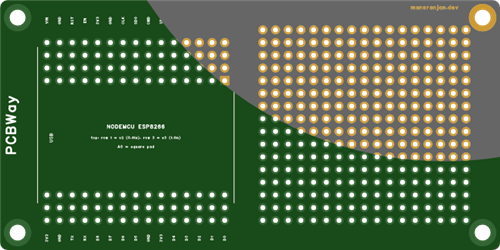
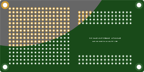
The board includes a fixed bottom header arrangement and additional top header rows for the different module widths.
This allows the same PCB design to support both module variants without requiring separate carrier boards.
Important assembly note: Install the upper header row corresponding to the width of your NodeMCU module.
Clearly Labeled Pin Connections
The pin connections are labeled directly on the PCB for easier circuit construction, debugging, and wiring.
The board provides access to the NodeMCU connections, including:
VIN
GND
RST
EN
3V3
CLK
SD0
CMD
SD1
SD2
SD3
RSV
A0
TX
RX
D0–D8
Clear labeling helps reduce wiring mistakes and makes the board easier to use for beginners, makers, students, and experienced electronics developers.
Extra Linked Holes
Additional linked solder holes are provided alongside the main header connections.
These provide convenient soldering points for jumper wires, external modules, sensors, and custom circuits.
The extra holes make it easier to route signals and power connections without overcrowding the NodeMCU header positions.
Large Universal Prototyping Area
The PCB includes a large dot-grid prototyping area for constructing custom electronic circuits directly on the board.
You can use this area for:
Sensors
Resistors
Capacitors
Diodes
Transistors
DIP integrated circuits
Pin headers
Jumper wires
Small interface circuits
Signal-conditioning circuits
Custom connectors
Additional electronic modules
This area allows the NodeMCU to be combined with additional hardware without requiring a separate PCB for every project.
Standard 2.54 mm Grid
The universal prototyping area uses a standard 2.54 mm (0.1-inch) spacing.
This grid is compatible with common through-hole components, DIP ICs, standard pin headers, and breadboard-compatible components.
It makes transferring circuits from a breadboard to a permanent PCB easier and provides flexibility for custom circuit layouts.
Plated-Through Holes
The prototyping pads feature:
1.0 mm finished hole diameter
1.8 mm pad diameter
Copper pads on both sides
Plated-through connections
The plated-through construction provides electrical continuity between layers and improves pad strength during soldering, desoldering, and circuit rework.
Mounting Holes
Mounting holes are included to allow the PCB to be installed inside project enclosures, mounted onto panels, or attached to mechanical structures.
They provide a convenient way to secure the board in permanent installations.
Applications
ESP8266 IoT Projects
The board is suitable for building a wide variety of Wi-Fi-enabled projects using the NodeMCU ESP8266.
Examples include:
Wireless sensor nodes
Temperature and humidity monitoring
Environmental monitoring
Wi-Fi data logging
Wireless control systems
Remote monitoring devices
Smart Home Automation
The NodeMCU can be combined with circuits built on the prototyping area to create custom home-automation hardware.
Possible projects include:
Smart switches
Relay controllers
Wi-Fi sensor modules
Home Assistant devices
Smart lighting controllers
Wireless automation systems
Custom ESPHome devices
Tasmota Projects
The board can be used as a development platform for ESP8266-based Tasmota hardware projects.
The universal prototyping area makes it possible to add interface circuits, sensors, connectors, and other components required by custom Tasmota applications.
ESPHome Projects
Build custom ESPHome devices using the NodeMCU ESP8266 module.
The board is useful for experimenting with GPIO connections, sensor interfaces, custom inputs, outputs, and hardware integrations.
Educational Electronics
This PCB is suitable for students, electronics hobbyists, makers, workshops, and beginners learning embedded electronics.
It can be used to learn:
PCB soldering
Circuit design
Microcontroller GPIO
Sensor interfacing
Wi-Fi communication
Embedded programming
Hardware prototyping
PCB assembly and rework
It provides a practical transition from breadboard experiments to permanent circuit construction.
Custom Hardware Development
When a project requires additional hardware beyond the NodeMCU development board, the prototyping grid allows you to construct custom circuits directly on the same PCB.
This can reduce development cost and simplify small-scale hardware projects.
Technical Specifications
SpecificationDetailsProjectNodeMCU ESP8266 Proto BoardCompatible modulesNodeMCU V2 / V3 / LoLinPCB dimensions100 × 50 mmPCB layers2PCB materialFR-4Thickness1.6 mmGrid pitch2.54 mm / 0.1 inchFinished hole diameter1.0 mmPad diameter1.8 mmHole typePlated-throughPad copperBoth sidesPrototyping areaUniversal dot gridMountingMounting holesLicenseCC BY-SA 4.0
Recommended PCB Manufacturing Settings
Recommended fabrication specifications:
Layers: 2
Material: FR-4
Thickness: 1.6 mm
Surface finish: HASL
Lead-free HASL: Recommended for educational projects and boards intended to be shared
Solder mask: Any colour
Silkscreen: White
Minimum finished hole: 1.0 mm
No special manufacturing options are required.
The board is designed for standard PCB fabrication processes.
Assembly Guide
Identify the NodeMCU module version you will use.
Select the correct top header row for the module width.
Install the required pin headers or female socket headers.
Check the USB connector orientation and accessibility.
Solder the NodeMCU headers carefully.
Use the universal dot-grid area to assemble additional circuitry.
Connect sensors, components, power, and signals using the labeled pads.
Verify power and signal connections before powering the completed circuit.
Using female socket headers is recommended if you want to remove, replace, or reuse the NodeMCU module.
Design Quality
The PCB design has been checked using Design Rule Check (DRC).
The design passes the DRC with zero errors.
The board uses standard manufacturing specifications and does not require special fabrication processes.
Open-Source Hardware License
This project is released under the Creative Commons Attribution-ShareAlike 4.0 International (CC BY-SA 4.0) license.
You are free to:
Manufacture the PCB
Use it in personal projects
Use it for educational purposes
Modify the PCB design
Create derivative designs
Share your improvements
Please provide attribution to the original designer and release derivative designs under the same license.
Part of the DIY Universal Boards Collection
This PCB is part of my DIY Universal Boards collection, featuring 24 open-source hardware designs.
The collection includes:
Universal dot-grid prototyping boards
Stripboards
Breadboard layouts
Raspberry Pi Pico carriers
ESP32 development-board carriers
ESP8266 development-board carriers
Arduino Nano carriers
Wemos D1 Mini carriers
C3 SuperMini carriers
Blue Pill carriers
Arduino Uno shields
Arduino Mega shields
Raspberry Pi HAT-size boards
SMD adapters
PCB rulers
LED chaser rulers
The goal of this collection is to provide reusable PCB building blocks for makers, students, hobbyists, engineers, and electronics developers.
Project Files
The Gerber files, documentation, and other open-source designs are available in the GitHub repository.
DIY Universal Boards Repository:
https://github.com/ElectroIoT/DIY-Universal-Boards
Designed by ElectroIoT.in
Designed and shared as part of my open-source electronics and DIY hardware projects.
Website: https://electroiot.in
GitHub: https://github.com/ElectroIoT/DIY-Universal-Boards
Build • Learn • Experiment • Share
NodeMCU ESP8266 Proto Board 100 x 50 mm
Project images are for reference only. Actual production is based on the manufacturing files on the project page.
Please review the designer's notes (e.g., PCB thickness) and select the appropriate options.
PCBWay is not responsible
for issues caused by unsuitable parameter selections.
For more important ordering information, please refer to
Read More


Raspberry Pi 5 7 Inch Touch Screen IPS 1024x600 HD LCD HDMI-compatible Display for RPI 4B 3B+ OPI 5 AIDA64 PC Secondary Screen(Without Speaker)
BUY NOW


- Comments(0)
- Likes(0)
More by MANORANJAN DAS
-
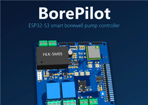 BorePilot - ESP32-S3 Smart Borewell Pump Controller
BorePilot is an open-source controller board for a single-phase submersible (borewell) pump. An ESP3...
-
 EasyArduino
 by ElectroIoTThe ultimate beginner’s board to learn, build, and master Arduino the easy ...
-
 Power Rail Proto Board 100 x 50 mm
Power Rail Proto Board 100 × 50 mmUniversal Prototyping PCB with Dual Power RailsThe Power Rail Prot...
-
 Breadboard PCB 100 x 50 mm
Breadboard PCB 100 × 50 mmProject OverviewThe Breadboard PCB 100 × 50 mm is a solderable prototyping...
-
 Mini Breadboard PCB 60 x 40 mm
Mini Breadboard PCB 60 × 40 mmProject OverviewThe Mini Breadboard PCB is a compact, solderable proto...
-
 Raspberry Pi Pico Proto Board 100 x 50 mm
Raspberry Pi Pico Proto Board — 100 × 50 mmWhy I made thisIn 2019, I shared a simple 100 × 50 mm DIY...
-
 ESP32 DevKit 38-pin Proto Board 100 x 50 mm
ESP32 DevKit 38-Pin Proto Board — 100 × 50 mmWhy I made thisIn 2019, I shared a simple 100 × 50 mm D...
-
 SMD Adapter Board 100 x 50 mm
SMD Adapter Board 100 × 50 mmUniversal SMD-to-Through-Hole Adapter & Prototyping PCBProject Over...
-
 STM32 Blue Pill Proto Board 100 x 50 mm
STM32 Blue Pill Proto Board 100 × 50 mmProject OverviewThe STM32 Blue Pill Proto Board is a universa...
-
 Raspberry Pi HAT-size Proto Board
Why I Made ThisIn 2019, I shared a simple 100 × 50 mm DIY universal...
-
 NodeMCU ESP8266 Proto Board 100 x 50 mm
NodeMCU ESP8266 Proto Board – 100 × 50 mm Universal Prototyping PCBProject OverviewThe NodeMCU ESP82...
-
 Wemos D1 mini Proto Board 50 x 45 mm
Wemos D1 Mini Proto Board – 50 × 45 mm Universal Prototyping PCBProject OverviewThe Wemos D1 Mini Pr...
-
 Arduino Uno Proto Shield
 – Universal Prototyping BoardProject OverviewThe Arduino Uno Proto Shield i...
-
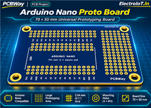 Arduino Nano Proto Board 70 x 50 mm
Arduino Nano Proto Board 70 × 50 mmUniversal Prototyping Board for Arduino NanoThe Arduino Nano Prot...
-
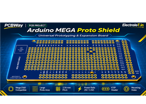 Arduino Mega Proto Shield
Arduino Mega 2560 Proto Shield – Universal Prototyping BoardProject OverviewThe Arduino Mega 2560 Pr...
-
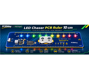 LED Chaser PCB Ruler 10 cm
A Functional PCB Ruler with a Rainbow LED ChaserThis project combines a pr...
-
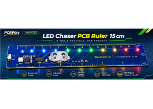 LED Chaser PCB Ruler 15 cm
Why I made thisIn 2019 I shared a simple 100 x 50 mm DIY universal board. I kept using it, and I kep...
-
 DIY Universal Board 100 x 50 mm V2
Why I made thisIn 2019 I shared a simple 100 x 50 mm DIY universal board. I kept using it, and I kep...
-
-
-
-
-
-
-
AudioLink – USB & Bluetooth LE Audio / Auracast Receiver with Balanced Line Outputs (nRF5340)
487 0 1 -
-
-
-
Émetteur Récepteur Optique Expérimental (communication UART ATtiny + fibre optique)
475 0 1