


Breadboard PCB 100 x 50 mm
Breadboard PCB 100 × 50 mm
Project Overview
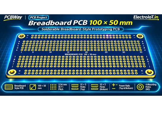
The Breadboard PCB 100 × 50 mm is a solderable prototyping board designed to reproduce the layout of a standard breadboard on a permanent PCB.
The idea is simple: build and test your circuit on a traditional breadboard, then transfer the components and connections hole-for-hole onto this PCB and solder them in place. This allows you to make a working prototype permanent without redesigning the circuit or changing the component layout.
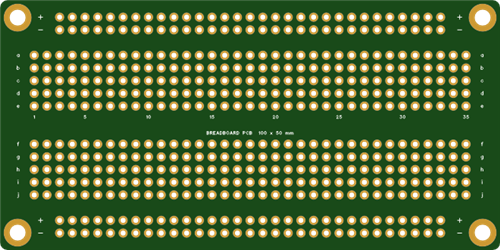
The board features a familiar breadboard-style arrangement with 35 columns, five-hole connection strips, a centre channel for DIP ICs, four power rails, and clearly marked row and column numbering.
Designed around the standard 2.54 mm (0.1-inch) pitch, it supports common through-hole electronic components, DIP integrated circuits, pin headers, and breadboard-compatible parts.
Why I Made This
In 2019, I shared a simple 100 × 50 mm DIY universal board. I kept using it and realised I wanted more board sizes and versions designed for the development boards and electronics I use regularly.
This led to the creation of a complete family of 24 open-source boards, including:
Universal prototyping boards
Dot-grid PCBs
Stripboard layouts
Breadboard-style solderable PCBs
Development-board carriers
Arduino shields
Raspberry Pi HAT-size boards
SMD adapter boards
PCB rulers
LED chaser rulers
All boards follow the same design philosophy: practical layouts, a standard 2.54 mm grid, clear labels, and easy-to-use PCB designs.
The Breadboard PCB 100 × 50 mm is one of these boards.
What's on the Board?
1. Breadboard-Compatible Layout
The PCB uses a familiar breadboard layout with 35 columns of component positions.
The upper section contains five-hole strips labelled:
a, b, c, d, e
The lower section contains five-hole strips labelled:
f, g, h, i, j
This makes it easy to transfer components from a conventional breadboard directly to the PCB using the same row and column positions.
2. Connected Five-Hole Strips
Each five-hole strip follows the familiar connection pattern of a breadboard.
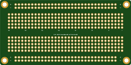
The connections are linked on the bottom side of the PCB, reproducing the electrical arrangement of a traditional breadboard.
This allows components to be placed in the same positions and connected using the same basic circuit layout.
3. Centre Channel for DIP ICs
A dedicated centre channel separates the upper and lower component sections.
This is suitable for placing DIP integrated circuits across the channel, just like on a traditional breadboard.
It supports convenient prototyping with:
DIP ICs
Operational amplifiers
Logic ICs
Timer ICs
Microcontroller ICs
Driver ICs
Other through-hole integrated circuits
4. Four Power Rails
The PCB includes four dedicated power rails marked:
Positive (+)
Negative (−)
Positive (+)
Negative (−)
These rails provide convenient power distribution for electronic circuits.
They can be used for:
VCC and GND
5V and GND
3.3V and GND
Dual power supplies
Analog and digital supply distribution
5. Clear Row and Column Labels
The PCB includes row letters and column numbers similar to a conventional breadboard.
This makes circuit construction easier and allows you to document circuit layouts using standard breadboard coordinates.
For example, components and jumper connections can be planned using the same row and column references before soldering.
6. Standard 2.54 mm Grid
All component positions use the standard:
2.54 mm / 0.1-inch pitch
This spacing is compatible with:
DIP integrated circuits
Standard pin headers
Through-hole resistors
Capacitors
LEDs
Transistors
Jumper wires
Breadboard-compatible components
Common electronic modules
7. Durable Through-Hole Pads
The board uses:
1.0 mm plated-through holes
1.8 mm copper pads
Copper pads on both PCB sides
The plated-through-hole construction helps provide mechanically strong solder joints and improves durability during component replacement and soldering rework.
The design is suitable for repeated experimentation, soldering, component replacement, and prototype development.
Specifications
SpecificationDetailsProduct nameBreadboard PCB 100 × 50 mmPCB size100 × 50 mmLayers2 layersMaterialFR-4Thickness1.6 mmGrid pitch2.54 mm / 0.1 inchComponent layoutBreadboard-styleColumns35Connection stripsFive-hole stripsRow labelsa–e and f–jCentre channelDIP IC compatiblePower railsFour, marked + and −Hole diameter1.0 mmPad diameter1.8 mmHole typePlated through-holePadsBoth sidesPCB design rule checkZero errorsLicenseCC BY-SA 4.0
Applications
This board is ideal for:
Making breadboard circuits permanent
Arduino and microcontroller experiments
Analog circuit prototyping
Digital logic experiments
Sensor circuits
LED projects
IC testing
Educational electronics
Electronics classrooms and workshops
Beginner DIY projects
Circuit debugging and testing
Small electronic device prototypes
Hobby electronics and maker projects
How to Use
Step 1 – Build Your Circuit
Assemble and test your circuit on a conventional solderless breadboard.
Step 2 – Transfer the Layout
Move each component to the same row and column position on the Breadboard PCB.
The familiar layout means you can transfer your circuit hole-for-hole without redesigning the arrangement.
Step 3 – Solder Components
Solder the components and connections to the PCB to create a permanent prototype.
Step 4 – Modify Connections
If you need to break a connected strip, you can cut the copper link using a knife.
This provides flexibility when your circuit requires isolated connections or a different electrical arrangement.
Manufacturing Recommendations
Recommended PCB manufacturing settings:
2-layer PCB
FR-4 material
1.6 mm thickness
HASL surface finish
Lead-free HASL recommended
Any solder mask colour
White silkscreen
Minimum hole size: 1.0 mm
No special manufacturing options are required.
Open-Source Design
This PCB is part of the DIY Universal Boards open-source project.
The project contains 24 PCB designs intended for DIY manufacturing, prototyping, modification, and experimentation.
The designs are released under:
Creative Commons Attribution-ShareAlike 4.0 (CC BY-SA 4.0)
You can manufacture the board yourself, modify the design, and share compatible improvements under the applicable license terms.
Project Files
Gerber file:
gerber/Gerber_Breadboard-PCB-100x50.zip
Documentation:
https://github.com/ElectroIoT/DIY-Universal-Boards/blob/main/docs/pcbway/08-Breadboard-PCB-100x50.md
GitHub Repository:
https://github.com/ElectroIoT/DIY-Universal-Boards
Designer: ElectroIoT
Website: https://electroiot.in
Project Summary
The Breadboard PCB 100 × 50 mm is a practical solution for converting tested breadboard circuits into permanent soldered prototypes. With its familiar five-hole strips, DIP IC centre channel, four power rails, standard 2.54 mm spacing, and clearly marked coordinates, it makes prototyping easier for beginners, students, makers, and electronics enthusiasts.
Build it on a breadboard. Transfer it hole-for-hole. Solder it permanently.
Breadboard PCB 100 x 50 mm
Project images are for reference only. Actual production is based on the manufacturing files on the project page.
Please review the designer's notes (e.g., PCB thickness) and select the appropriate options.
PCBWay is not responsible
for issues caused by unsuitable parameter selections.
For more important ordering information, please refer to
Read More


Raspberry Pi 5 7 Inch Touch Screen IPS 1024x600 HD LCD HDMI-compatible Display for RPI 4B 3B+ OPI 5 AIDA64 PC Secondary Screen(Without Speaker)
BUY NOW

- Comments(0)
- Likes(0)
More by MANORANJAN DAS
-
 BorePilot - ESP32-S3 Smart Borewell Pump Controller
BorePilot is an open-source controller board for a single-phase submersible (borewell) pump. An ESP3...
-
 EasyArduino
 by ElectroIoTThe ultimate beginner’s board to learn, build, and master Arduino the easy ...
-
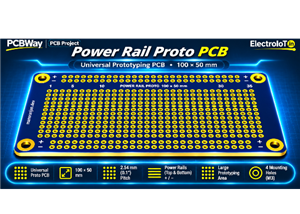 Power Rail Proto Board 100 x 50 mm
Power Rail Proto Board 100 × 50 mmUniversal Prototyping PCB with Dual Power RailsThe Power Rail Prot...
-
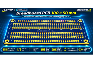 Breadboard PCB 100 x 50 mm
Breadboard PCB 100 × 50 mmProject OverviewThe Breadboard PCB 100 × 50 mm is a solderable prototyping...
-
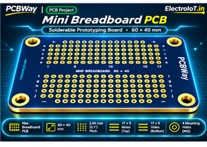 Mini Breadboard PCB 60 x 40 mm
Mini Breadboard PCB 60 × 40 mmProject OverviewThe Mini Breadboard PCB is a compact, solderable proto...
-
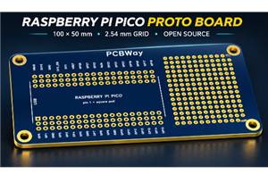 Raspberry Pi Pico Proto Board 100 x 50 mm
Raspberry Pi Pico Proto Board — 100 × 50 mmWhy I made thisIn 2019, I shared a simple 100 × 50 mm DIY...
-
 ESP32 DevKit 38-pin Proto Board 100 x 50 mm
ESP32 DevKit 38-Pin Proto Board — 100 × 50 mmWhy I made thisIn 2019, I shared a simple 100 × 50 mm D...
-
 SMD Adapter Board 100 x 50 mm
SMD Adapter Board 100 × 50 mmUniversal SMD-to-Through-Hole Adapter & Prototyping PCBProject Over...
-
 STM32 Blue Pill Proto Board 100 x 50 mm
STM32 Blue Pill Proto Board 100 × 50 mmProject OverviewThe STM32 Blue Pill Proto Board is a universa...
-
 Raspberry Pi HAT-size Proto Board
Why I Made ThisIn 2019, I shared a simple 100 × 50 mm DIY universal...
-
 NodeMCU ESP8266 Proto Board 100 x 50 mm
NodeMCU ESP8266 Proto Board – 100 × 50 mm Universal Prototyping PCBProject OverviewThe NodeMCU ESP82...
-
 Wemos D1 mini Proto Board 50 x 45 mm
Wemos D1 Mini Proto Board – 50 × 45 mm Universal Prototyping PCBProject OverviewThe Wemos D1 Mini Pr...
-
 Arduino Uno Proto Shield
 – Universal Prototyping BoardProject OverviewThe Arduino Uno Proto Shield i...
-
 Arduino Nano Proto Board 70 x 50 mm
Arduino Nano Proto Board 70 × 50 mmUniversal Prototyping Board for Arduino NanoThe Arduino Nano Prot...
-
 Arduino Mega Proto Shield
Arduino Mega 2560 Proto Shield – Universal Prototyping BoardProject OverviewThe Arduino Mega 2560 Pr...
-
 LED Chaser PCB Ruler 10 cm
A Functional PCB Ruler with a Rainbow LED ChaserThis project combines a pr...
-
 LED Chaser PCB Ruler 15 cm
Why I made thisIn 2019 I shared a simple 100 x 50 mm DIY universal board. I kept using it, and I kep...
-
 DIY Universal Board 100 x 50 mm V2
Why I made thisIn 2019 I shared a simple 100 x 50 mm DIY universal board. I kept using it, and I kep...
-
-
-
-
-
-
-
AudioLink – USB & Bluetooth LE Audio / Auracast Receiver with Balanced Line Outputs (nRF5340)
487 0 1 -
-
-
-
Émetteur Récepteur Optique Expérimental (communication UART ATtiny + fibre optique)
475 0 1