



|
KiCADKicad
|
LM20MeshNode V2
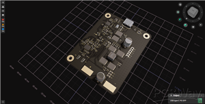
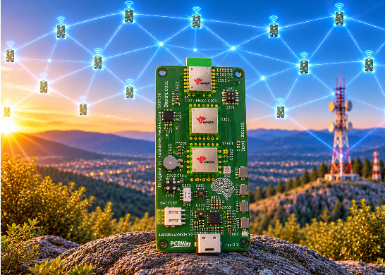
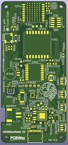
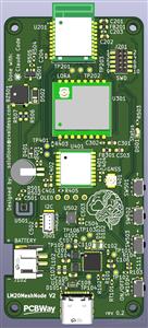
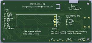
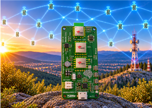
Pocket Meshtastic node built around the Nordic nRF54LM20A (Minew ME54BS13 module), with a Minew MS21SF1 (SX1262) LoRa module, a Minew ME31GR02 GNSS receiver and a Nordic nPM1300 PMIC for a single-cell LiPo battery. It connects to the phone over Bluetooth LE.
Features
MCU: Minew ME54BS13 (nRF54LM20A, Bluetooth LE with integrated antenna), USB-C to the nRF54LM20A USB port, 2×5 1.27 mm Cortex Debug (SWD) header (J201) and debug UART pads.
LoRa: Minew MS21SF1-SX1262 (SX1262, up to 22 dBm). The antenna goes to the U.FL connector on the module itself. The RF switch inside the module is driven by DIO2, so the MCU drives no RXEN/TXEN line. The module supply has its own filter footprint: FB301 (0 Ω, or a ferrite bead) and C303.
GNSS: Minew ME31GR02 (Beken BK166X chip) with U.FL antenna connector (J401). L401 (47 nH) feeds an active antenna from the module's VCC_RF output; a passive antenna also works if it is not a DC short. The GNSS supply (nPM1300 BUCK1) is off at power-up and is switched by firmware.
GNSS backup: a rechargeable Seiko MS621FE coin cell (BT401) on V_BCKP, charged from 3.3 V through a BAT54WS diode and 1 kΩ. It keeps the RTC and ephemeris data while the board is off, for faster fixes.
Power: nPM1300 PMIC with USB-C input and ESD protection, 1S LiPo charger (JST PH 2.0, J102), on-board 10 kΩ NTC, 3.3 V main rail (BUCK2), power button (SW101) on SHPHLD, charge and error LEDs, and a battery voltage divider to an ADC input.
User interface: 0.91" 128×32 OLED (SSD1306) on the back, three side buttons (UP, OK, DOWN), magnetic buzzer and a status LED.
Sensors: Nyfea SHT41-P-NF temperature/humidity sensor (SHT41 compatible), thermally isolated by a slot, and an ST LSM6DS3TR-C IMU wired for wake-on-motion (INT1 on P0.02).
Expansion: 4-pin 1 mm I²C connector (J501, Qwiic-style pinout: GND, 3.3 V, SDA, SCL).
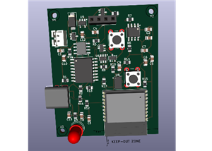
Board: 4 layers (signal / GND / 3.3 V / signal), 40 × 85.68 mm, 1.6 mm, M2 mounting holes. All SMD parts are on the top side.
Firmware notes
The nPM1300 starts with the battery charger disabled. Firmware must enable charging over I²C. The board is designed so that LoRa and Bluetooth work without a PMIC driver.
The MS21SF1 has a crystal, not a TCXO: do not define a DIO3 TCXO voltage. Use DIO2 as the RF switch and define no RXEN/TXEN pins.
The GNSS rail (BUCK1) must be set to 3.3 V and enabled by firmware.
The ME31GR02 uses a Beken BK166X chip, which Meshtastic does not detect yet. It talks NMEA at 115200 bps by default, prints $POLRS or $BKCHIP at start-up and is configured with $POLCFG… commands.
While the GNSS is unpowered or running from the backup cell, no MCU pin connected to it may be driven high: put the UART TX pin in input mode with a pull-down. This is why R405 (reset) is not fitted.
Meshtastic firmware
The lm20meshnode variant is under review upstream. It was written for revision 0.1 (Ebyte modules). All three pull requests are open, and nothing has run on hardware yet:
Part Pull request
Meshtastic variant (draft, on top of the nRF54LM20-DK support in #12130) meshtastic/firmware#12354Arduino core variant
andyshinn/nRF54_Arduino#3Bootloader board andyshinn/nRF54_Bootloader#3
Until they are merged, the variant builds from the feat/lm20meshnode-variant branch of cvaldess/firmware with pio run -e lm20meshnode. The core and the bootloader come from forks (the core at a pinned commit, the bootloader at the tag v0.5.0-lm20meshnode.1).
What the variant does on revision 0.1:
nPM1300, set up over I²C at boot: BUCK1 (GNSS rail) at 3.3 V, switched by the PMIC's GPIO0, which the GPS code drives from P1.05; battery charger on at 200 mA (NPM1300_CHARGE_CURRENT_MA), 4.20 V (4.00 V in the warm region), with the on-board 10 kΩ NTC; USB input limit 500 mA. BUCK2, the 3.3 V main rail, is left on its VSET2 setting. After USB is unplugged and plugged in again, the PMIC goes back to its 100 mA startup input limit until the next boot.
LoRa with RXEN from the MCU and TXEN from DIO2, no TCXO. GNSS on Serial1 at 38400 bps.
Buttons: UP, DOWN and OK navigate the screen (up/down input driver). OLED at 128×32, buzzer, status LED, battery level from AIN2, and the SHT41 and LSM6DS3TR-C drivers.
USB-C: console and Meshtastic API over USB CDC; firmware updates over USB (serial DFU or a UF2 drive) or over Bluetooth.
Bootloader (64 KB, application at 0x10000): hold OK at reset for USB DFU (UF2 drive LM20MN-BOOT), OK + DOWN for Bluetooth OTA. The status LED shows the bootloader state.
Revision 0.2 needs these changes in the variant: DIO2 as the RF switch and no RXEN pin (LoRa), a detection probe for the Beken GNSS at 115200 bps, the GNSS UART TX pin left as an input with a pull-down while the GNSS is off, and no GNSS reset pin.
Design files
KiCad 10 project: nrflm20-meshnode.kicad_pro. The root schematic has five sheets: power, MCU, LoRa, GNSS and interface.
libs/: project symbols, footprints and 3D models. The MS21SF1 and ME31GR02 footprints were converted from Minew's design files (docs/gen/huellas_minew.py). The ME54BS13 3D model was drawn from its datasheet (docs/gen/modelo3d_me54bs13.py).
3D models of the MS21SF1 and ME31GR02 are not included yet: they are Minew's files and are waiting for Minew's permission to publish them. The footprints already point to libs/meshnode.3dshapes/MS21SF1_PCB_V1.0.step and libs/meshnode.3dshapes/GNSS_MODULE_1010.step, so a clone of this repository renders the board without those two modules.
docs/: block diagram and schematic drafts (SVG). docs/gen/ has the Python scripts used during the design.
lista_compra.txt: shopping list (in Spanish).
Some footprints and 3D models come from easyeda2kicad (${EASYEDA2KICAD}). The footprints are stored in the board file, but their 3D models are not included in this repository.
Credits
Designed by: solutions@cvaldess.com
Made with: Claude Code, KiCad and Konnect-EDA
Sponsors: PCBWay and MinewSemi (ME54BS13, MS21SF1 and ME31GR02 modules)
LM20MeshNode V2
Project images are for reference only. Actual production is based on the manufacturing files on the project page.
Please review the designer's notes (e.g., PCB thickness) and select the appropriate options.
PCBWay is not responsible
for issues caused by unsuitable parameter selections.
For more important ordering information, please refer to
Read More


Raspberry Pi 5 7 Inch Touch Screen IPS 1024x600 HD LCD HDMI-compatible Display for RPI 4B 3B+ OPI 5 AIDA64 PC Secondary Screen(Without Speaker)
BUY NOW


- Comments(0)
- Likes(0)
More by Carlos Valdes
-
 LM20MeshNode V2
Pocket Meshtastic node built around the Nordic nRF54LM20A (Minew ME54BS13 module), with a Minew MS21...
-
 INA350_Nucleo-64_Hat
INA350 Nucleo-64 HatTest board that plugs onto an STM32 NUCLEO-64 through the morpho connectors. It ...
-
 BY1515Controller_Nucleo-64_Hat
BY1515 Controller Nucleo-64 HatAdd-on board for an STM32 NUCLEO-64 (designed for the NUCLEO-G474RE) ...
-
 usb_ch341_e22p
USB → SPI adapter for using an EBYTE E22P-868M30S LoRa module (SX1262 + PA, 30 dBm / 1 W) with mesht...
-
 Wiznet_5500_EVB_Pico2_E22P
A custom PCB carrier board built around the WIZnet W5500-EVB-Pico2 (an RP2350 with an on-board W5500...
-
 E80-900M2213S_SE050_Breakout
A breakout board for the Ebyte E80 family of 16 × 26 mm dual-band LoRa modules (sub-GHz and 2.4 GHz)...
-
 LM20MeshNode
Pocket Meshtastic node built around the Nordic nRF54LM20A (Minew ME54BS13 module), with ...
-
 Multiple IMU Breakout Board
What is it about?This board is the first piece of hardware for AI MotoLogger, a data logger I'm desi...
-
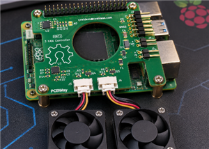 Rpi3FanHatPlus
Raspberry Pi 5 HAT+ that drives the three fans of a case with a Microchip EMC2303 fan ...
-
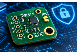 NXP SE050 Secure Element Breakout Board
A minimal breakout board for the NXP EdgeLock SE050E2HQ1 secure element, bringing the I²C interface ...
-
-
-
-
-
-
-
AudioLink – USB & Bluetooth LE Audio / Auracast Receiver with Balanced Line Outputs (nRF5340)
487 0 1 -
-
-
-
Émetteur Récepteur Optique Expérimental (communication UART ATtiny + fibre optique)
475 0 1