


|
|
SE050E2HQ1/Z01Z3ZNXP
|
x 1 | |
|
|
CL05B104KO5NNNCSamsung
|
x 1 | |
|
|
CC0402KRX7R9BB333YAGEO
|
x 1 | |
|
|
RC0402FR-074K7LYageo
|
x 1 | |
|
|
RC0402FR-07100KLYageo
|
x 1 |

|
KiCADKicad
|
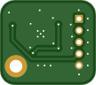
NXP SE050 Secure Element Breakout Board
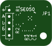
A minimal breakout board for the NXP EdgeLock SE050E2HQ1 secure element, bringing the I²C interface out to a 5-pin 2 mm header. 16.42 × 14.56 mm, two layers, all passives 0402.
ENA is not optional — this is the first thing to get wrong. R3 pulls it to ground, so the SE050 powers up in deep power-down and will not answer on I²C until ENA goes high. If your scan of the bus finds nothing at 0x48, this is almost certainly why.
You have two ways to handle it:
Drive ENA from a GPIO (pin 4 of the header). This is the reason the pin is broken out: it gives the host a hard power switch over the secure element, and deep power-down draws under 5 µA.
Close JP1 if you have no pin to spare. It is a solder jumper on the top side, labelled on the silkscreen, and it ships open — bridge the two pads with solder and the chip is permanently enabled. Leave pin 4 of the header unconnected in that case.
Closing JP1 costs you only the deep power-down mode, which is the one mode controlled by that pad. Software power-down (~430–480 µA, with state retention, woken by a falling edge on SDA) still works either way. It also leaves R3 as a permanent 100 kΩ load across the rail, about 33 µA.
Note that firmware commonly ignores this pin — the Meshtastic SE050 driver, for one, never touches it — so if you are dropping this board under existing software, JP1 is probably what you want.
The I²C target address of the SE050 is 0x48.
There is deliberately no capacitor between VOUT (pin 15) and VCC (pin 18). Application note AN13483 §8.2.2 asks for that node to be left undecoupled on an I²C part that uses deep power-down, and this board follows it. Two builds were made to test the point — one with a 33 nF there and one without — and they were indistinguishable across every measurement available without an oscilloscope: identical enable/disable timing, identical 1 µA deep power-down current, and the same result on every functional test. The note is obeyed because obeying it costs nothing, not because a failure was reproduced.
Design notes
Worth reading before you reuse this in your own layout — most of it comes straight from the SE050 data sheet and is easy to get wrong.
The ISO7816 pins are left unconnected on purpose. The SE050 also speaks ISO7816 and ISO14443 as a smart card, but that interface is not enabled in generic SE050 configurations — NXP enables it only on customer request (see AN12436, which does not list it for any stock part number). On the E2 those pads are inert, and the data sheet's own recommendation for pins 3 (IO1), 13 (CLK) and 16 (IO2) is "n.c. (recommended)".
Pin 14 (RST_N) is the exception, and it goes to ground here. For that pad the data sheet offers no floating option — "if not used then connect to VCC or VSS" — and of the two, VSS is the one that holds up in every state of this board. RST_N is referenced to VCC, and VCC is fed from VOUT through an internal switch that opens in deep power-down: with ENA low, VCC drops to 0 V while VIN stays up, so a pin tied to the 3V3 rail would sit above its own reference. Ground sidesteps that, and it cannot hold the part in reset because RST_N is only active when the ISO7816 interface is enabled, which it is not on the E2.
Note that IO1 and IO2 double as the I²C controller pins (SDA and SCL respectively) — the SE050 acting as a bus master to talk directly to a sensor and sign its readings. The E2 supports that at up to 1 Mbit/s. If you want it, those are the pads to break out.
VOUT is a switch, not a regulator. Pin 15 (VOUT) supplies pin 18 (VCC) through an internal power switch of about 1.1 Ω, which is why they are tied together here — the arrangement the data sheet requires for deep power-down to work. In deep power-down VOUT and VCC are switched off entirely and only the I²C pads stay supplied from VIN.
The exposed pad is ground. It is stitched to the ground plane with five 0.6 mm vias (0.3 mm drill) — four at the corners and one in the centre — leaving 0.175 mm of clearance at the tightest to the edge of the 1.95 × 1.95 mm pad. If you have the stencil made, check that your fab tents the via barrels, or solder will wick down them during reflow.
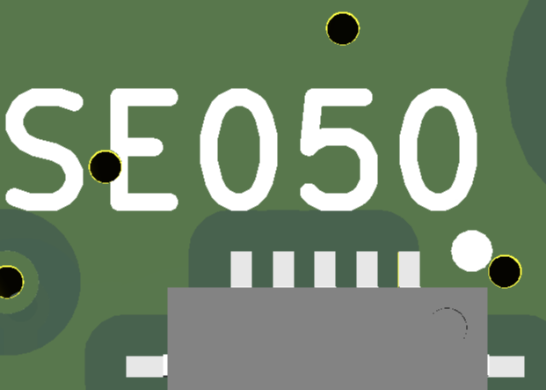
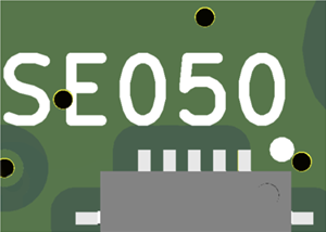
Two fiducials, diagonally opposite, for machine assembly. Each is a 1 mm copper dot in a 2 mm solder mask opening, with a 3 mm keepout drawn as a rule area on the top copper so the ground pour backs away and leaves the camera a clean target. If you hand-solder this board they are simply two bare copper dots and you can ignore them. Note that the keepout is a top-layer rule: the bottom pour runs straight under the fiducials, which is fine, because the camera cannot see through the board.
Pinout (J1, 1×5, 2 mm pitch)
Pin Net Notes
1 +3.3V supply, feeds VIN (pin 12)
2 SDA I²C data, 4.7 kΩ pull-up on board
3 SCL I²C clock, 4.7 kΩ pull-up on board
4 ENA enable — drive high to use the chip, or close JP1
5 GND
NXP SE050 Secure Element Breakout Board
Project images are for reference only. Actual production is based on the manufacturing files on the project page.
Please review the designer's notes (e.g., PCB thickness) and select the appropriate options.
PCBWay is not responsible
for issues caused by unsuitable parameter selections.
For more important ordering information, please refer to
Read More


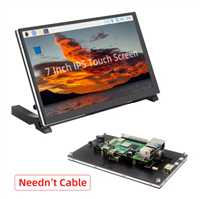
Raspberry Pi 5 7 Inch Touch Screen IPS 1024x600 HD LCD HDMI-compatible Display for RPI 4B 3B+ OPI 5 AIDA64 PC Secondary Screen(Without Speaker)
BUY NOW

- Comments(0)
- Likes(0)
More by Carlos Valdes
-
Émetteur Récepteur Optique Expérimental (communication UART ATtiny + fibre optique)
77 0 1 -
SmallOLED - Live PC Stats, Animated Clocks & Audio Visualizer
897 0 3 -
"Talking Multimeter": Arduino-Based Speech Add-on for Multimeters with SCPI Protocol
525 0 1 -
Programmable Mist Maker - XIAO / QT PY Extension
2989 2 3 -
RadioHAT - Raspberry Pi radio development platform
2540 0 4 -
-
-