



|
KiCADKicad
|
E80-900M2213S_SE050_Breakout
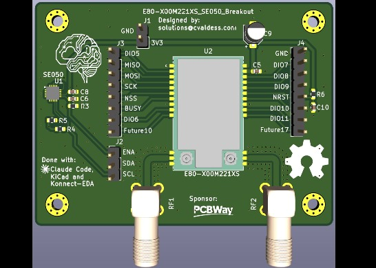
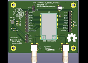
A breakout board for the Ebyte E80 family of 16 × 26 mm dual-band LoRa modules (sub-GHz and 2.4 GHz), with an NXP EdgeLock SE050E2 secure element next to it. The module footprint is generic and takes any of these:
Module Radio chip Bands E80-900M2212S, E80-400M2212S Semtech LR2021 850–930 MHz or 410–493 MHz, plus 2.4 GHz E80-900M2213S, E80-400M2213S Semtech LR1121 850–930 MHz or 410–493 MHz, plus 2.4 GHz
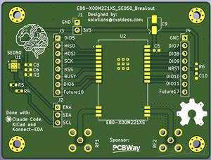
Every signal pin of the module comes out on two 8-pin headers that follow the module's own two rows: the SPI bus, BUSY, reset and all the DIO lines, plus the two pads Ebyte reserves for future expansion. The secure element has its own 3-pin header (I²C and enable) and power comes in on a 2-pin header. Each antenna port has its own right-angle SMA connector, fed by a 50 Ω line.
68.92 × 51.80 mm, two layers, 1.6 mm, four M2.5 mounting holes. Designed in KiCad 10. The project is self-contained: the symbols, footprints and 3D models of every non-standard part are in lib/, so it opens on any machine without installing extra libraries.
Connectors
All logic is 3.3 V. Pin 1 of each header is the square pad.
J1 — power (1×2, 2.54 mm)
Pin Signal Notes
1 GND
2 3V3 the only supply: E80 VCC (module pin 25) and SE050 VIN
J2 — secure element (1×3, 2.54 mm)
Pin Signal Connects to Notes
1 ENA SE050 ENA must be driven high, see below
2 SDA SE050 I²C data 4.7 kΩ pull-up on board
3 SCL SE050 I²C clock 4.7 kΩ pull-up on board
J3 — radio, module pins 2 to 10 (1×8, 2.54 mm)
Pin Signal Module pin Notes
1 DIO5 2 not connected on the M2213S
2 MISO 3 SPI
3 MOSI 4S PI
4 SCK 5 SPI
5 NSS 6 SPI chip select
6 BUSY 7
7 DIO6 9 M2212S only
8 Future10 10 reserved by Ebyte, see Module footprint
J4 — radio, module pins 17 to 24 (1×8, 2.54 mm)
Pin Signal Module pin Notes
1 GND
2 DIO7 24
3 DIO8 23
4 DIO9 22 radio interrupt on the M2213S (LR1121), see below
5 NRST 21 10 kΩ pull-up and 100 nF to GND on board
6 DIO10 20 not connected on the M2213S
7 DIO11 18 M2212S only
8 Future17 17 reserved by Ebyte, see Module footprint
Which DIO is the interrupt. On the LR1121 (E80-xxxM2213S) the interrupt comes out on DIO9, J4 pin 4. Host code written for SX126x radios often calls this pin DIO1; the board uses the module's name. On the LR2021 (E80-xxxM2212S) the interrupt line is chosen in software, and both DIO5 (J3 pin 1) and DIO9 (J4 pin 4) are available. RadioLib's LR2021 driver defaults to DIO5, so point your driver's IRQ pin at the one you wire.
ENA is not optional. R3 (100 kΩ) pulls it to ground, so the SE050 powers up in deep power-down and will not answer on I²C until the host drives ENA high. If a bus scan finds nothing at 0x48, this is the reason. Unlike the standalone SE050 breakout, this board has no solder jumper to tie ENA high. If you have no GPIO to spare, connect J2 pin 1 to 3V3 externally.
Antenna ports
The silkscreen calls the two ports RF1 (SMA1, module pin 12) and RF2 (SMA2, module pin 15), because Ebyte swapped the bands between the two module families:
Module RF1 (pin 12) RF2 (pin 15)
E80-xxxM2212S (LR2021) sub-GHz 2.4 GHz
E80-xxxM2213S (LR1121) 2.4 GHz sub-GHz
Both pin assignments come from the pin tables in Ebyte's user manuals. Both lines are identical 50 Ω feeds, so either band works on either port. Fit the right antenna to each port for the module you mount.
Design notes
RF feed lines. Both antenna ports use grounded coplanar waveguide on the top layer: a 1.35 mm track with a 0.35 mm gap to the ground pour, with ground poured on both layers and stitched with via fences along each line. On the stack-up declared in the project (1.6 mm, 1.51 mm core, εr 4.5) that works out at about 49.5–55 Ω, depending on the calculation model. Each line leaves the module's antenna pad through a short 0.8 mm neck (the pad is narrower than the line), runs along the module's bottom edge, turns down through one arc of about 1.2 mm radius and runs straight into the SMA centre pin. The lines are about 12.9 mm (RF1) and 14.4 mm (RF2) long.
Clearances come from rules, not from hand edits. The ground pour is set to the 0.35 mm RF gap. A custom rule in E80-900M2213S_SE050_Breakout.kicad_dru moves it back to 0.5 mm from everything else. A second rule opens a 1.0 mm anti-pad around the SMA centre pins on both layers, which reduces the capacitance of the through-hole transition. If you change the gap, refill the zones before plotting. kicad-cli pcb drc --refill-zones --save-board does it from the command line with the project's own rules.
The SE050 circuit is the one from se050-breakout, where an earlier revision was built and validated on hardware. VOUT and VCC are tied together with no capacitor, RST_N goes to ground and the ISO7816 pins are left unconnected. The reasons for each of these are in that repository's design notes. The exposed pad goes to ground through the same five 0.3 mm vias, one in the centre and one under each of the four paste windows. What is different here: 0603 passives, no ENA jumper, and the I²C pull-ups are on this board.
Module footprint. E80_Ebyte:E80-Generic in lib/ is Ebyte's own footprint for the E80-xxxM2212S, with two pads added. It has all 26 edge positions (1.27 mm pitch, 1.8 × 0.8 mm pads centred on the module edge) and the bottom ground pad 27, which is a 3 × 3 grid of 0.8 mm pads. The origin is the centre of the module body. Pads 10 and 17 are the positions Ebyte marks as reserved for future expansion. No current module has a pad there. The manual does not give their position, so they continue the 1.27 mm pitch from pads 9 and 18. Their nets are called Future10 and Future17 and go to the headers. With an E80-xxxM2213S fitted, pads 9, 10, 17 and 18 have no module pad above them and pads 2 and 20 are not connected inside the module. The matching symbol, E80_Ebyte:E80-Generic, names the antenna pins RF1 and RF2 rather than by band.
3D models. The E80 model is Ebyte's STEP file for the E80-xxxM2212S, positioned from its own geometry: its castellations line up with the module pads and the two IPX connectors sit next to pins 12–15, as in Ebyte's drawing. The SMA model is the manufacturer's STEP file, positioned from its own geometry and checked against the connector's datasheet (6 × 6 mm body, 17 mm long, 9.5 mm high with 3.3 mm pins). The thread overhangs the bottom edge of the board.
Fabrication
Bare board. Everything a board house needs is in gerber/, and the same files are zipped in E80-900M2213S_SE050_Breakout_gerber.zip for upload:
Gerber X2 for both copper layers, both solder masks, the top silkscreen, both paste layers and the board outline, plus the Gerber job file
Excellon drill files, plated and non-plated separately, with drill maps
There is no bottom silkscreen. All 307 holes are plated (240 of them are 0.3 mm vias). The smallest track and clearance are 0.2 mm, which is within any standard two-layer service.
E80-900M2213S_SE050_Breakout
Project images are for reference only. Actual production is based on the manufacturing files on the project page.
Please review the designer's notes (e.g., PCB thickness) and select the appropriate options.
PCBWay is not responsible
for issues caused by unsuitable parameter selections.
For more important ordering information, please refer to
Read More


Raspberry Pi 5 7 Inch Touch Screen IPS 1024x600 HD LCD HDMI-compatible Display for RPI 4B 3B+ OPI 5 AIDA64 PC Secondary Screen(Without Speaker)
BUY NOW


- Comments(0)
- Likes(0)
More by Carlos Valdes
-
 E80-900M2213S_SE050_Breakout
A breakout board for the Ebyte E80 family of 16 × 26 mm dual-band LoRa modules (sub-GHz and 2.4 GHz)...
-
 LM20MeshNode
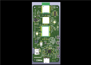
Pocket Meshtastic node built around the Nordic nRF54LM20A (Minew ME54BS13 module), with ...
-
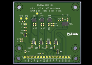 Multiple IMU Breakout Board
What is it about?This board is the first piece of hardware for AI MotoLogger, a data logger I'm desi...
-
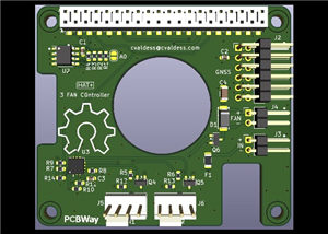 Rpi3FanHatPlus
Raspberry Pi 5 HAT+ that drives the three fans of a case with a Microchip EMC2303 fan ...
-
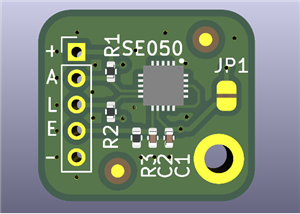 NXP SE050 Secure Element Breakout Board
A minimal breakout board for the NXP EdgeLock SE050E2HQ1 secure element, bringing the I²C interface ...
-
-
-
-
AudioLink – USB & Bluetooth LE Audio / Auracast Receiver with Balanced Line Outputs (nRF5340)
328 0 1 -
-
-
-
Émetteur Récepteur Optique Expérimental (communication UART ATtiny + fibre optique)
384 0 1 -
SmallOLED - Live PC Stats, Animated Clocks & Audio Visualizer
1488 0 3