



|
KiCADKicad
|
Multiple IMU Breakout Board
What is it about?
This board is the first piece of hardware for AI MotoLogger, a data logger I'm designing for a KTM 250 SX-F motocross bike. The final logger will record motion (IMU), position and speed from a dual-frequency GNSS receiver, suspension travel, brakes, wheel speeds, engine data from the ECU's CAN bus (listen-only) and a wideband lambda sensor. The target is to time-stamp every channel against GNSS time to within 100 µs.
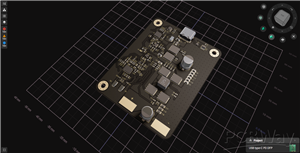
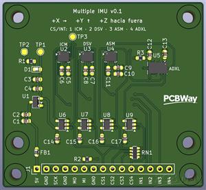
Before designing the main board, I have to choose its IMU. That's what this board is for: it puts four IMUs side by side on one rigid 4-layer PCB, so they all feel exactly the same shocks and the same vibration.
Why did I make it?
A motocross bike is a hard place for an inertial sensor. Landings, ruts and crashes produce acceleration peaks that I haven't found measured anywhere, and most IMUs stop at ±16 g. The engine also shakes everything, and that vibration can shift a gyroscope's offset. Datasheets rarely say how a part behaves in that environment.
Four separate breakout boards wouldn't answer the question: each sensor would sit on a different board, with its own mounting and its own resonances. On one rigid PCB the comparison is direct, and it costs less than four evaluation modules.
The four candidates:
TDK ICM-45686: ±32 g, ±4000 °/s. The current choice for the main board.
ST LSM6DSV320X: ±16 g plus a high-g channel up to ±320 g in the same FIFO. If it performs well, one chip could do the job of two.
ST ASM330LHH: automotive grade (AEC-Q100), rated to +105 °C, but only ±16 g. The backup if the enclosure gets too hot.
Analog Devices ADXL375: a ±200 g accelerometer, used as the reference for peaks above 32 g.
How does it work?
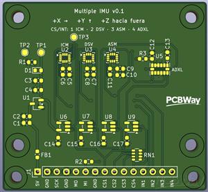
Board: 54 × 50 mm, 4 layers (signals / GND / 3.3 V / signals), 1.6 mm thick, all parts on the top side. It has four M3 mounting holes and two extra holes for a cable tie next to the connector.
Power: 5 V comes in from the development board through a ferrite bead. An on-board 3.3 V LDO (Torex XC6206) feeds the sensors, and every power pin has its own decoupling capacitor.
One SPI bus for all four: SPI mode 3 at 5 MHz, with a separate chip select for each sensor. The ADXL375 can't switch off its I²C interface, so SPI traffic meant for the other sensors could look like I²C to it. A single-gate OR (SN74LVC1G32) in front of each sensor's data input fixes this: while a sensor isn't selected, its input is held high.
Hardware time stamps: each sensor's interrupt line goes to a 32-bit timer input-capture channel on an STM32U5 Nucleo (NUCLEO-U5A5ZJ-Q). Every FIFO batch gets a precise time stamp, with no interrupt latency.
One connector: a 1×15 header with 2.54 mm pitch carries 5 V, GND, SPI, four chip selects and four interrupts. On the bench it uses Dupont wires. On the bike, the cable is soldered and tied down.
MEMS-friendly layout (following ST's TN0018):
No copper, tracks or vias under the sensors on the top layer.
The sensors sit in a row with their axes aligned (the ADXL375 is rotated 90°), and the axes are marked on the silkscreen.
Stencil apertures are reduced on the LGA pads, so there's less solder paste under the sensors.
A small check for the AliExpress part: the ADXL375 reports the same device ID as the ADXL345. The firmware therefore checks the reading at rest: about 20 counts per g for a real ADXL375, about 256 for a relabelled ADXL345.
Test plan:
On the bench: check that all four respond, measure noise at rest against the datasheets, and hit the board with a rubber mallet to cross-check the high-g channels.
On a Yamaha YZ 125 test bike: find out whether real peaks go past 16 g or 32 g, record the engine vibration spectrum and gyro drift under vibration, and read the board temperature from each sensor's internal thermometer.
The results will decide the main board's IMU: the LSM6DSV320X alone, the ICM-45686 alone, or one of them plus the ADXL375.
Status
I'll assemble the board by hand using the stencil, then test it on the bench and on the bike. I plan to update this page with the results.
Multiple IMU Breakout Board
Project images are for reference only. Actual production is based on the manufacturing files on the project page.
Please review the designer's notes (e.g., PCB thickness) and select the appropriate options.
PCBWay is not responsible
for issues caused by unsuitable parameter selections.
For more important ordering information, please refer to
Read More


Raspberry Pi 5 7 Inch Touch Screen IPS 1024x600 HD LCD HDMI-compatible Display for RPI 4B 3B+ OPI 5 AIDA64 PC Secondary Screen(Without Speaker)
BUY NOW


- Comments(0)
- Likes(0)
More by Carlos Valdes
-
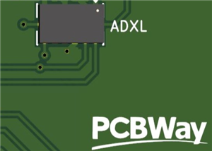 Multiple IMU Breakout Board
What is it about?This board is the first piece of hardware for AI MotoLogger, a data logger I'm desi...
-
 Rpi3FanHatPlus
Raspberry Pi 5 HAT+ that drives the three fans of a case with a Microchip EMC2303 fan ...
-
 NXP SE050 Secure Element Breakout Board
A minimal breakout board for the NXP EdgeLock SE050E2HQ1 secure element, bringing the I²C interface ...
-
-
-
AudioLink – USB & Bluetooth LE Audio / Auracast Receiver with Balanced Line Outputs (nRF5340)
235 0 0 -
-
-
-
Émetteur Récepteur Optique Expérimental (communication UART ATtiny + fibre optique)
349 0 1 -
SmallOLED - Live PC Stats, Animated Clocks & Audio Visualizer
1391 0 3 -
"Talking Multimeter": Arduino-Based Speech Add-on for Multimeters with SCPI Protocol
784 0 1