


|
ATMEGA328PB-ANMicrochip Technology
|
x 1 | |

|
74HCT573D,653NXP USA Inc.
|
x 1 | |
|
|
LCD DISPLAY 16X2 & BLLCD DISPLAY 16X2 & BL
|
x 1 |

|
KiCad 9.0 |
|

|
arduino IDEArduino
|
LCD-DisplayController
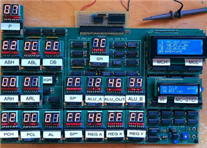
The TTL 6510 computer was designed with connectors for plugging in HexDisplayControllers for displaying register contents etc. Originally these hex displays were used for the micro code steps, instruction register and micro code outputs. Instead of looking up the meaning of instruction codes or the micro code bit group meanings, I decided to switch to multi line displays I had laying around.
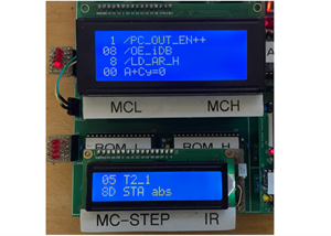
The instruction code and micro step counter can be displayed on a 2 line LCD text display module, while the 4 micro step signal groups can better be displayed on a 4 line LCD text display module.

Both modules can be interfaced in the same way, so the schematics for both can be the same. There are two 8-bit ports to read in from. Since the Arduino processor doesn't have enough pins for both, they are multiplexed to one 8-bit bus.
The LCD module is connected via 4 bit databus as in the example codes for the the Arduino. Then it only needs the resistor for the back light and a potentiometer for the contrast.

The boards in the picture above are hand wired, but to make it nicer and repeatable there needs to be a PCB layout for both cases. The two LCD modules 16x2 and 20x4 have different dimensions and so I changed the design for 2 connectors in parallel, one to be used for the 16x2 module and the other to be used by the 20x4 module.
Another 4-bit header was added to include reading in more bits that are currently wired to single LEDs on the side of the TTL 6510 computer board Rev A. Rev B is now routed to those headers.

The layout is made to plug in the two different sizes of LCD modules and to break off the part only needed for the larger module. The PCB had been made at PCBway.

The blank board as it came from PCBway.

Board broken off and assembled for LCD 16x2.

Board fully assembled with LCD 16x2.

Board assembled for LCD 20x4.

Board fully assembled with LCD 20x4.

Similar to the HexDisplayController, the processor code is written in the Arduino IDE, then programmed onto the UNO R3 board. The processor is then removed from the UNO board and plugged into the LCD board. Here is a screenshot of the MicroCode_In version containing the 6502 instruction strings.

The second screenshot shows string definitions for the micro code output signals.
LCD-DisplayController
*PCBWay community is a sharing platform. We are not responsible for any design issues and parameter issues (board thickness, surface finish, etc.) you choose.


Raspberry Pi 5 7 Inch Touch Screen IPS 1024x600 HD LCD HDMI-compatible Display for RPI 4B 3B+ OPI 5 AIDA64 PC Secondary Screen(Without Speaker)
BUY NOW


- Comments(1)
- Likes(0)
 More by Engineer
-
 TTL 6510 Computer
IntroductionI know, this is not the first TTL CPU/Computer and not the last. But I got interested in...
TTL 6510 Computer
IntroductionI know, this is not the first TTL CPU/Computer and not the last. But I got interested in...
-
 LCD-DisplayController
The TTL 6510 computer was designed with connectors for plugging in HexDisplayControllers for display...
LCD-DisplayController
The TTL 6510 computer was designed with connectors for plugging in HexDisplayControllers for display...
-
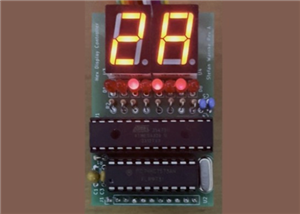 Hex Display Controller
This small PCB reads an 8-bit input and converts the binary code to a 2 digit 7-segment LED as hexad...
Hex Display Controller
This small PCB reads an 8-bit input and converts the binary code to a 2 digit 7-segment LED as hexad...
-
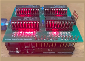 Arduino IO Expander
This IO expander plugs into an Arduino Uno to add more controllable pins. It can be used for instanc...
Arduino IO Expander
This IO expander plugs into an Arduino Uno to add more controllable pins. It can be used for instanc...
-
Programmable Mist Maker - XIAO / QT PY Extension
171 0 0 -
RadioHAT - Raspberry Pi radio development platform
180 0 1 -
-
-
-
-
ARPS-2 – Arduino-Compatible Robot Project Shield for Arduino UNO
2766 0 5 -
A Compact Charging Breakout Board For Waveshare ESP32-C3
3273 3 8 -
AI-driven LoRa & LLM-enabled Kiosk & Food Delivery System
3528 2 2


