


G-EDM EVOIII Pulseboard (Deprecated)
The new pulseboard can be found here: https://www.pcbway.com/project/shareproject/G_EDM_Gapstorm_Pulseboard_14dd4341.html
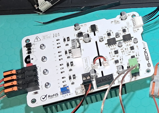
To build the G-EDM electrical discharge machine it requires two PCBs. The motionboard and the pulseboard.
Due to the cutouts the pulseboard does flex on pressure with the default 1.6mm thickness. It is not a big deal but using 2mm PCB thickness makes them a lot stiffer and it is recommended to order them with 2mm PCB thickness.
The new EVOIII Motionboard can be found here but the PCBA service is not tested yet. The board itself works:
https://www.pcbway.com/project/shareproject/W532897ASC41_motionboard_evoIII_rev3_bb113e0f.html
Link to the old/deprecated EVOII Motionboard: https://www.pcbway.com/project/shareproject/G_EDM_Low_budget_DIY_Wire_EDM_machine_34e1e043.html
Note that the connection between DPM/DPH and Motionboard changed with the EVOIII Motionboard. ESP RX/TX on the EVOII version was swapped. On the EVOIII board the communication interface mirrors the DPM/DPH output terminal. See details on Github:
https://github.com/G-EDM/G-EDM/blob/main/README.md
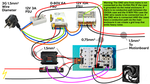
The pulseboard as it can be ordered here is not ready for use out of the box and can not be used with a linear voltage source.
It requires a DPM8605 or DPH8909 as power input.
I recommend the DPH8909 together with a 0-80v 6A variable PSU. This combination will provide up to 80v. I think 80v is already too high and 70v seems to be nice.
The DPM8605 is limited to 60V and can be powered with a 65-72V PSU. Max input voltage on the DPM is 75v if I remember correct.
The G-EDM has a communication interface to interact with the DPM/DPH and program then if needed. On the fly changes of voltage and current for probing is one thing that makes it very useful.
No matter what concept it used, the DPH and the DPM are available in different versions that use different protocols. The version required is the TTL version. This is important. On Amazon it seems that they only have the non TTL version of the DPH8909. On Ebay they have all versions.
Adjust vFd
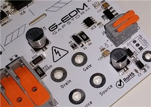
The poti on the board needs to be adjusted first and then the two JST connectors can be bridged. This is important. Never connect the small JST bridge without adjusting the voltage feedback first.
The Poti acts as a voltage divider on the bus voltage and the factory setting is around 50%. That means that for example at 80v input it would provide 40v into the sensor circuit and thus may damage things. The current is very low and some people already made this mistake without damaging anything. But it could damage something.
Adjusting it is done in two steps. The first step is rough adjustment to bring the voltage down into a save zone. The second is finetuning that is done after everything is connected and the display shows the feedback values.
Initial rough adjustment:
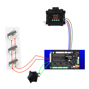
Connect a voltage source to the big power terminal and connect a multimeter to the left JST connector as shown in the image. Set the input voltage on the power terminal to the max voltage that will be used. 80v is the max voltage that should be used but people who use the DPM to power their build have a limit at 60v. So it is either 60v or 80v depending on the build.
With the voltage supplied to the power terminal adjust the poti until the multimeter reads a value below 5v. 3-4v is ok. This is just to have everything in a safe zone. Lowering the value is done by turning the poti counter clockwise if I remember correct.
Now it is save to connect the little JST double head wire. It would also be ok to not use the JST wire and use some zero OHM resistors to connect the sensor circuit to the pulse voltage bus.
Fine tuning:
After everything is wired up to the motionboard and the display is working we can fine tune vFd (voltage Feedback).
- Turn everything on
- Set the on/off switch that is connected to the motionboard and acts as estop two to OFF. With the switch in OFF position it will not start the process and we can work with the active PWM and integrated scope.
- Turn on PWM by touching the start/stop button on the front page of the UI on the display. With the ON/OFF switch in OFF state this will turn PWM on without starting the process and will activate the scope and start updating the values of the feedback.
- The important reading is on the top left of the scope and titled vFd. This reading should be around 4000 while the pulseboard has the maximum voltage used on the terminal. It should not peak at to 4095 and best practice is to adjust it until it is just very close below 4000. It doesn't need to be perfect.
- Done.
G-EDM EVOIII Pulseboard (Deprecated)
*PCBWay community is a sharing platform. We are not responsible for any design issues and parameter issues (board thickness, surface finish, etc.) you choose.


Raspberry Pi 5 7 Inch Touch Screen IPS 1024x600 HD LCD HDMI-compatible Display for RPI 4B 3B+ OPI 5 AIDA64 PC Secondary Screen(Without Speaker)
BUY NOW


- Comments(0)
- Likes(3)
More by Roland Lautensack
-
 G-EDM Gapstorm Pulseboard
G-EDM Gapstorm (Pulseboard)The G-EDM Gapstorm was designed to replace the EVOIII Pulseboard with a m...
G-EDM Gapstorm Pulseboard
G-EDM Gapstorm (Pulseboard)The G-EDM Gapstorm was designed to replace the EVOIII Pulseboard with a m...
-
 G-EDM EVOIII Motionboard
https://gedm.org/This board comes with a more thoughtful placement of all th...
G-EDM EVOIII Motionboard
G-EDM EVOIII Motionboardhttps://gedm.org/This board comes with a more thoughtful placement of all th...
-
 G-EDM EVOIII Pulseboard (Deprecated)
The new pulseboard can be found here: https://www.pcbway.com/project/shareproject/G_EDM_Gapstorm_Pul...
G-EDM EVOIII Pulseboard (Deprecated)
The new pulseboard can be found here: https://www.pcbway.com/project/shareproject/G_EDM_Gapstorm_Pul...
-
 G-EDM Motionboard
Note from PCBWay: This page only includes the motionboard. To build the G-EDM it also requires the p...
G-EDM Motionboard
Note from PCBWay: This page only includes the motionboard. To build the G-EDM it also requires the p...
-
Programmable Mist Maker - XIAO / QT PY Extension
241 0 0 -
RadioHAT - Raspberry Pi radio development platform
263 0 1 -
-
-
-
-
ARPS-2 – Arduino-Compatible Robot Project Shield for Arduino UNO
2821 0 6 -
A Compact Charging Breakout Board For Waveshare ESP32-C3
3326 3 8 -
AI-driven LoRa & LLM-enabled Kiosk & Food Delivery System
3619 2 2


