


|
|
ATTINY85-20PU |
x 1 | |
|
|
0603 0.1uf ceramic capacitor |
x 1 | |
|
|
1254 li ion battery |
x 1 | |
|
|
SMD tactile Switch |
x 1 | |
|
|
SMD slide switch |
x 1 | |
|
|
Some wires |
x 1 |

|
KiCad 9.0 |
|

|
arduino IDEArduino
|
Earring for my Girlfriend ❤️
1. How it All Started 💕
A while ago, it was her birthday. During that period, I was occupied with my practical examinations and couldn’t plan a celebration or even arrange a present for her. Time passed, and although she understood the situation completely, I still felt a sense of guilt for not being able to make her day special.
I knew she doesn’t prefer expensive or overly fancy gifts. Instead, she values thoughtful effort. So I decided that when I finally gave her something, it should reflect both my appreciation and the creativity I could contribute. I wanted a gift that combined personal effort with a touch of engineering and something handmade, custom, and beautifull.
2. Design Inspiration
The idea of using a ring-shaped PCB with a central battery cutout was inspired by the internal circuit design of Apple Airtags.
3. Version-1 Started at-Mid May
3.1. Components Selection
3.1.1. MCU
The initial concept was straightforward: a tiny PCB populated with multiple RGB LEDs and a mode-select button to cycle through lighting patterns. However, achieving this in an ultra-compact form factor while maintaining stability, brightness, and runtime quickly became a design challenge.
The first decision point was selecting the microcontroller. I needed a device with at least two digital pins, compact packaging, and sufficient flash memory to store LED animation code. My initial thought was the ATtiny10 due to its very small footprint. However, the limitation became immediately clear — it provides only 1 KB of flash memory, which is insufficient to run even a basic FastLED animation example (typically requiring 3–4 KB at minimum).
To meet the memory requirements, I moved instead to the ATtiny85, which offers:
8 KB flash memory
Small 8-pin DIP/SOIC footprint
Timings compatible with WS2812B signal requirements
Enough capacity for multiple animation modes, not just a single blink routine, With this selection, the project gained flexibility to implement more than simple LED blinking and allowed room for pattern sequencing, color transitions, and potential future enhancements.
3.1.2. Power Regulation Strategy: DC–DC Boost Conversion
Both the ATtiny85 and WS2812B LEDs require a stable operating voltage in the range of 4.2–5.0 V. A single lithium-ion coin cell or compact Li-ion source cannot deliver this voltage directly, especially under dynamic LED load conditions. Therefore, a boost conversion stage was necessary to elevate the battery voltage to a regulated 5 V.
To achieve this, I selected a miniature step-up converter capable of maintaining stable output while accommodating the limited form factor of the wearable PCB. The chosen device was the TPS613222A (VBR marking code) — a highly compact DC–DC boost converter that supports:
Input range: 0.9 V to 5.5 V
Fixed output: 5.0 V regulated
Load capability: up to 500 mA when boosting from 3.0 V to 5.0 V
Package: ultra-small footprint suitable for wearable electronics
This converter comfortably satisfies the transient current peaks required by WS2812B LEDs, particularly during full-brightness RGB or white output conditions, where current spikes are significant and fast regulation response is critical.
A reference design from the TI datasheet was used to implement the boost stage. The layout ensures minimal ripple, short routing for the switch node, and appropriate decoupling to avoid LED signal noise or flicker during rapid current draw.
This is what I designed in KiCad using the TI datasheet as a reference.
3.1.3 Choosing LED Pakage
For the LEDs, the choice was clear: the Adafruit Neopixel (WS2812B) series, which I have used previously with reliable performance and excellent visual output during animations. The WS2812B family is available in multiple package sizes, and while the smallest footprint would have been ideal for this design, it was not available from my supplier at the time.[Adafruit NeoPixel Addressable 1515 LEDs]
Therefore, I selected the WS2812B 2020 package — a compact addressable RGB LED format that provided the required brightness, color consistency, and spatial efficiency for this miniature wearable PCB.
Image from Adafruit Website [WS2812B-2020]
3.1.4. Switches
There are two switches used in this project:
Mode Switch
A small tactile switch is used to change the LED animation modes.
The ATtiny85 can technically support around 4–5 modes with its 8 KB flash, but I am using only two because the animations I chose take more space in memory.
(If someone wants more modes, they can use lighter animation effects that take less flash—check the firmware section below.)
Power Switch
A tiny slide switch is used to turn the whole circuit on and off.
It can handle around 80 mA, which is more than enough for this setup and fits well in the very limited space of the PCB.
4. Version-2 Started at-Mid Dec
4.1. Additions
I Found this Module by this reddit post and this supporting Blog
For maintaining a stable 5 V supply on such a small wearable PCB, I needed a booster that was tiny but still able to handle the current spikes from WS2812 LEDs. After trying earlier designs, I selected the ME2108, which is a compact PFM step-up DC/DC converter. It supports a wide input range from around 0.9 V to 6.5 V and can boost to output voltages anywhere between 2.0 V and 7.0 V, depending on the version. In my case, I used the fixed 5 V variant to keep things simple.
Under normal operating conditions, the ME2108 can deliver up to ~400 mA when boosting from 3.0 V to 5.0 V, which is enough for short bursts of LED animations without dimming or flicker. The switching frequency is around 180 kHz, and efficiency stays roughly in the 80–85% range, depending on the load, which is acceptable for this tiny form factor.
In the next version, I will include this booster in my circuit because it works quite perfectly for the setup.
4.2. Schematic & Layout
Below are the schematic and PCB layout images from my design. I’ve added clear screenshots here for quick reference, and the full Gerber files can be downloaded from the Files section below.
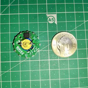
The PCB is very small, so I panelized it into a set of four. This helps save a lot of cost.
The complete editable KiCad project is also available on GitHub — the repository link is provided at the end of this page.
I have included my YouTube channel name "Replica" as silkscreen branding on the PCB. If anyone wants to remove or replace the branding with their own name or logo, you can simply edit the KiCad file and regenerate the Gerber output.
ame board design with standard 1.6 mm FR4 thickness, and the second iteration worked successfully.
4.3. Battery selection
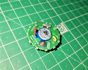
The battery I selected for the first version of the PCB was a 3V CR1226 coin cell. It did light up the circuit, but only for a very short period of time. The main issue was its low current capability—around 50 mA with 3 volt. After boosting from 3V to 5V, the available current drops even further, so the LEDs were not getting enough power.
Different animations draw different amounts of current, and with such a small battery, the voltage would dip and cause flickering or unstable behavior. To run the circuit properly and avoid these fluctuations, So I decided to upgrade the battery.
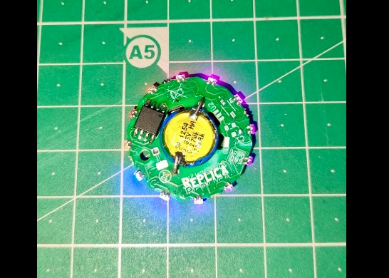
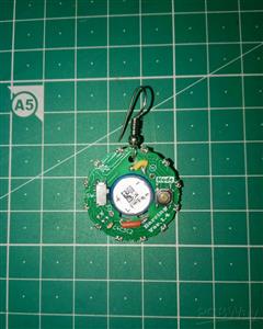
The 1254 Li-ion battery has the same 12 mm diameter as the CR1225 cell, with a voltage range of 3.7–4.2 V and a capacity of 70 mAh. This is enough to drive all the LEDs, and it removes the need for a step-up booster. As long as the battery remains above around 3.5 V, it can power the LEDs directly, making this Li-ion cell a suitable choice for this project.
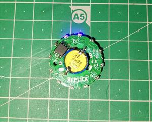
5. Testing WS2812B LED on Circuit.
Before testing the onboard LEDs with the ATtiny85, I must verify that all LEDs are correctly soldered to the PCB and that no pads are left unsoldered.
I tried two animations from the FastLED library.
Keep in mind that using the same animation will not always work on the ATtiny85, as it has only 8 KB of flash memory, while the Arduino Nano has 32 KB. Therefore, we need to program compressed versions of FastLED examples because most FastLED animations are high-definition and consume a large amount of flash memory.
As we plan to store more than one animation and toggle them with a mode button, we must write the program to use very little flash memory so we can fit more modes.
6. Programming At-tiny85
6.1. Program At-tiny85 form Digispark USB Module
I initially thought it would be very easy to program the ATtiny85 using a Digispark USB module. My plan was to buy a Digispark board, plug it into the laptop, select the Digispark board manager, upload the code, and that’s it. It programmed successfully, and when I connected Pin 2 of the ATtiny85 as the data pin for the WS2812B LED rail, it worked—but only while the ATtiny was still on the Digispark board.
After this, I looked up the Digispark circuit diagram and realized it is completely different from what I had assumed.
the IC pin-2 is PB3 which is connected to WS2812b led data pin and IC pin-3 Is PB4 which is connected to mode button for changing mode of animation
The ATtiny85 does not work alone after removing it from the Digispark board because the board provides essential support: a 10k pull-up on the RESET pin, and the correct clock settings that the Micronucleus bootloader depends on. When the chip is programmed through Digispark, Micronucleus sets specific fuse and clock configurations (like 16.5 MHz PLL for USB). After removal, reset pull-up, and clock environment, the bootloader cannot start correctly and your blink code never runs.
If we want to program the IC using the Digispark USB module, it is necessary to include these components.
A tutorial showing how the ATtiny85 with the Digispark bootloader gets programmed and needs those USB components (pull-ups, zeners, etc.).
6.2. Program At-tiny85 with Arduino Nano
I followed this tutorial for program the At-tiny85 from Arduino
Thanks to DIY TECH BROS
This is the link to be used in the preferences menu:
"https://drazzy.com/package_drazzy.com_index.json"
One thing to which is keep in mind while Programming the IC, Use 16 Mhz (PLL) Clock instead of 8Mhz, As the FastLED uses several math-heavy functions like sin, cos, pow, sqrt, color blending, and HSV calculations, which require more processing speed. At 8 MHz, the ATtiny85 often cannot perform these calculations also maintaining the strict timing required for WS2812/Neopixel LEDs, causing failure at Displaying Animation
Everything else remain same, thanks to DIY TECH BROS
6.3. Firmware Explanation (Code Walkthrough)
This firmware controls 12 WS2812B LEDs using an ATtiny85, with a single button to switch between two animation modes.
Library & Definitions
#include <FastLED.h>
FastLED is used to generate accurate WS2812B timing and manage color data efficiently on the ATtiny85,
#define NUM_LEDS 12
#define DATA_PIN 3
#define MODE_PIN 4
#define LED_TYPE WS2811
#define COLOR_ORDER GRB
#define BRIGHTNESS 60
NUM_LEDS defines the number of LEDs on the PCB
DATA_PIN is the WS2812B data line
MODE_PIN is connected to the tactile switch
LED_TYPE WS2811 ensures compatible timing for WS2812B
BRIGHTNESS limits current draw for wearable use
LED Buffer
CRGB leds[NUM_LEDS];
This array stores RGB data for all LEDs and is passed to FastLED for output.
Shared Animation Variables
int pos = 0;
int dir = 1;
uint8_t hue = 0;
These variables are used mainly by the Cylon animation:
pos tracks the active LED
dir controls direction of movement
hue stores the current color value
Mode Control
uint8_t mode = 0;
mode = 0 → Pride2015 animation
mode = 1 → Cylon animation
Button Debounce Variables
bool lastButtonStable = HIGH;
bool lastButtonRead = HIGH;
unsigned long lastDebounceTime = 0;
const unsigned long debounceDelay = 30;
These variables implement a non-blocking debounce using millis().
Setup Function
void setup() {
delay(500);
A short delay ensures power stability before LED initialization.
FastLED.addLeds<LED_TYPE, DATA_PIN, COLOR_ORDER>(leds, NUM_LEDS)
.setCorrection(TypicalLEDStrip)
.setDither(BRIGHTNESS < 255);
Registers the LED array
Applies standard color correction
Enables dithering at reduced brightness
FastLED.setBrightness(BRIGHTNESS);
Sets global brightness to reduce peak current.
pinMode(MODE_PIN, INPUT_PULLUP);
The button is wired to ground; a press pulls the pin LOW.
Button Handling in loop()
bool reading = digitalRead(MODE_PIN);
Reads the current state of the mode button.
if (reading != lastButtonRead) {
lastDebounceTime = millis();
}
lastButtonRead = reading;
Resets the debounce timer whenever the button state changes.
if ((millis() - lastDebounceTime) > debounceDelay) {
Checks if the input has been stable long enough.
if (reading != lastButtonStable) {
lastButtonStable = reading;
Updates the stable state of the button.
if (lastButtonStable == LOW) {
mode ^= 1;
A valid press toggles the animation mode.
pos = 0;
dir = 1;
hue = 0;
Resets animation variables so each mode starts cleanly.
Mode 0 – Pride2015 Animation
if (mode == 0) {
pride();
FastLED.show();
}
Calls the pride() function
Updates LEDs without blocking delays
Timing is handled internally using millis()
Mode 1 – Cylon Animation
fill_solid(leds, NUM_LEDS, CRGB::Black);
Clears all LEDs before drawing the next frame.
leds[pos] = CHSV(hue, 255, 255);
FastLED.show();
delay(35);
Lights a single LED at position pos using HSV color space.
pos += dir;
Moves the LED forward or backward.
if (pos >= NUM_LEDS - 1) {
dir = -1;
hue += 16;
} else if (pos <= 0) {
dir = 1;
hue += 16;
}
Reverses direction and changes color when the LED hits either end.
Pride2015 Function
void pride() {
This function generates a complex rainbow animation using:
beatsin88() for smooth oscillation
Sine-based brightness modulation
Gradual color blending via nblend()
CRGB newcolor = CHSV(hue8, sat8, bri8);
nblend(leds[pixelnumber], newcolor, 64);
This ensures smooth transitions without harsh color jumps.
This firmware controls 12 WS2812B LEDs using an ATtiny85, with a single button to switch between two animation modes.
6.4. Flash Used
I used two animations from the FastLED library: the Pride 2025 effect and a compressed one-LED Cylon animation.
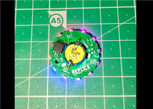
7. The Result
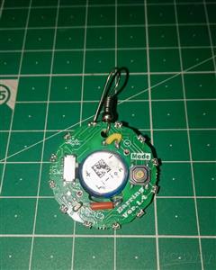
To make this PCB an earring, attach a French hook or Ear wire to the PCB.
Light up
youtube-replica
Illustration Video
Bye-Bye, Have a Nice day
Earring for my Girlfriend ❤️
Project images are for reference only. Actual production is based on the manufacturing files on the project page.
Please review the designer's notes (e.g., PCB thickness) and select the appropriate options.
PCBWay is not responsible
for issues caused by unsuitable parameter selections.
For more important ordering information, please refer to
Read More


Raspberry Pi 5 7 Inch Touch Screen IPS 1024x600 HD LCD HDMI-compatible Display for RPI 4B 3B+ OPI 5 AIDA64 PC Secondary Screen(Without Speaker)
BUY NOW


- Comments(0)
- Likes(1)
More by Vishal soni
-
 Earring for my Girlfriend ❤️
1. How it All Started A while ago, it was her birthday. During that period, I was occupied with my p...
Earring for my Girlfriend ❤️
1. How it All Started A while ago, it was her birthday. During that period, I was occupied with my p...
-
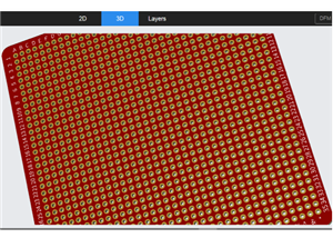 universal pcb
Why Use a 2.54mm Pitch Universal PCB for Your Projects?A Universal PCB with a 2.54mm (0.1 inch) pitc...
universal pcb
Why Use a 2.54mm Pitch Universal PCB for Your Projects?A Universal PCB with a 2.54mm (0.1 inch) pitc...
-
 At tiny_85 analog watch
IntroductionI was inspired to design this watch after reading about Sam DeRose's Nerd Watch which ta...
At tiny_85 analog watch
IntroductionI was inspired to design this watch after reading about Sam DeRose's Nerd Watch which ta...
-
Programmable Mist Maker - XIAO / QT PY Extension
1061 2 1 -
RadioHAT - Raspberry Pi radio development platform
861 0 2 -
-
-
-
-
ARPS-2 – Arduino-Compatible Robot Project Shield for Arduino UNO
3322 0 6 -
A Compact Charging Breakout Board For Waveshare ESP32-C3
3930 3 8 -
AI-driven LoRa & LLM-enabled Kiosk & Food Delivery System
4316 2 2


