


|
|
Resistor 1Kohm |
x 5 | |
|
|
LED Red |
x 1 | |
|
|
LCD Display 7_Segment |
x 4 | |
|
|
555 Timer |
x 1 | |
|
|
L7805 |
x 1 | |
|
|
Capacitor 100nF |
x 3 | |
|
|
Capacitor 220nF |
x 1 | |
|
|
Resistor 1Mohm |
x 1 | |
|
|
Resistor 10Kohm |
x 1 | |
|
|
Capacitor 10uF |
x 2 | |
|
|
Resistor 22Kohm |
x 1 | |
|
|
Resistor 47Kohm |
x 1 | |
|
|
Resistor 120Kohm |
x 1 | |
|
|
Capacitor 47nF |
x 1 | |
|
|
ICL7107 |
x 1 | |
|
|
Capacitor 100pF |
x 1 | |
|
|
Diode 1N4148 |
x 2 | |
|
|
Resistor 5Kohm |
x 1 |

|
Altium DesignerAltium Designer
|
|
|
|
Inventhub |
Digital Voltmeter PCB Board To Measure Voltages Accurately
Digital Voltmeter:
Digital voltmeters are used to measure potentials between two different points and they display the values in the form of digits accurately that is why they are more reliable to use. The chances of making errors are less as compared to the analog voltmeter. They are more stable and provide a better interface to the user.
Design Implementation:
We are designing a circuit that will measure Voltages in Digital. All the inputs from those two potentials will be analog so we have to make all these values digital. We have many options to convert analog values to digital but we will use ICL7107 IC due to its functionality as it will convert Analog to Digital and also give us output for 7 segments which will be easy for us. ICL7107 IC will make outputs for 7 segments internally, we don’t need any additional circuit for 7 segment data converter.
Circuit Working:
First of all, We need positive and negative voltages for our circuit. Negative will be supplied to ICL7107. We will make these negative voltages with the help of a timer IC. NE555 IC will be used in Astable mode(output oscillates at a particular frequency and generate pulses in the rectangular waveform). In Astable mode, 555 will provide us continuous voltage when it will be triggered. For positive we are using 7805 LDO. It will help us connect 9-12V as input of the circuit and provide us with a constant 5V positive for ICL7107 IC. Then, we need two potential differences on pins 31 and 35. After that, we have to make the internal clock circuit for ICL7107. R1 and C1 will be used for the frequency of the internal clock. Then, we have to connect outputs from ICL7107 with 7 segments. We are using common anode 7-segments and we will supply +5V to them then, We need to ground them or provide 0 to complete their circuit. So, ICL7107 will give 0 or ground to reference pins of 7-segments. As ICL7107 is making a decision on when to turn ON 7-Segments LEDs. 0 may vary for a different set of arrangements. Like if we have to display 1 on 7-segment we have to ground or provide 0 to B and C and it may vary for a different set of numbers that will be displayed.
Components Management Libraries:
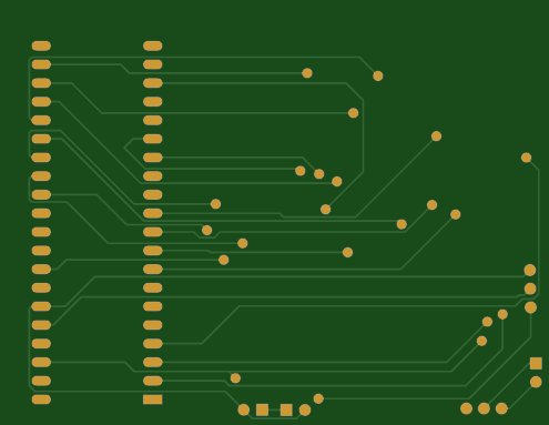
Before implementing the design in the PCB file, I have created the symbol and footprint of each component. Then I have uploaded each symbol linked with their footprint on Inventhub. Each component is attached to its supply chain. While designing the PCB board it is important to take care of the footprint and dimensions of each component. Footprints should be exactly the same as per component size otherwise your design will not be perfect.

Digital Voltmeter PCB Board To Measure Voltages Accurately
*PCBWay community is a sharing platform. We are not responsible for any design issues and parameter issues (board thickness, surface finish, etc.) you choose.


Raspberry Pi 5 7 Inch Touch Screen IPS 1024x600 HD LCD HDMI-compatible Display for RPI 4B 3B+ OPI 5 AIDA64 PC Secondary Screen(Without Speaker)
BUY NOW


- Comments(1)
- Likes(2)
More by Arshmah Arshmah Shahkar
-
 Control Household Appliances Remotely- PCB Board
This is a simple remote controller circuit consisting of two main parts:TransmitterReceiverThese kin...
Control Household Appliances Remotely- PCB Board
This is a simple remote controller circuit consisting of two main parts:TransmitterReceiverThese kin...
-
 Better Quality of Sound with Class D Audio Amplifier PCB Board
What is Class D Amplifier?As the name suggests D, is a digital amplifier. It is also known as a swit...
Better Quality of Sound with Class D Audio Amplifier PCB Board
What is Class D Amplifier?As the name suggests D, is a digital amplifier. It is also known as a swit...
-
 Digital Voltmeter PCB Board To Measure Voltages Accurately
Digital Voltmeter:Digital voltmeters are used to measure potentials between two different points and...
Digital Voltmeter PCB Board To Measure Voltages Accurately
Digital Voltmeter:Digital voltmeters are used to measure potentials between two different points and...
-
 Control Direction of DC Motor Using H-Bridge Driver PCB
Working of H-Bridge Driver:H- Bridge driver circuit is made up of four transistors that act as switc...
Control Direction of DC Motor Using H-Bridge Driver PCB
Working of H-Bridge Driver:H- Bridge driver circuit is made up of four transistors that act as switc...
-
 FPGA PCB Using ICE40 To Drive 64×64 LED Matrix
ICE40 FPGA:The ICE40 chip is an ultra-low-power FPGA and sensor manager designed for ultra-low power...
FPGA PCB Using ICE40 To Drive 64×64 LED Matrix
ICE40 FPGA:The ICE40 chip is an ultra-low-power FPGA and sensor manager designed for ultra-low power...
-
 Heart Rate Monitoring PCB Board Design for Workout
The heart rate monitor is used to measure heartbeats in a minute. It can be useful in many applicati...
Heart Rate Monitoring PCB Board Design for Workout
The heart rate monitor is used to measure heartbeats in a minute. It can be useful in many applicati...
-
 Determine Electric Field Strength To Adjust Gain and Transmitting Range-PCB Design
Description:This PCB design board is useful for the RF signals to determine the strength of the sign...
Determine Electric Field Strength To Adjust Gain and Transmitting Range-PCB Design
Description:This PCB design board is useful for the RF signals to determine the strength of the sign...
-
 H-Bridge Inverter PCB Design Board
The H bridge inverter is used to convert DC voltages to AC voltages. An h bridge is common in genera...
H-Bridge Inverter PCB Design Board
The H bridge inverter is used to convert DC voltages to AC voltages. An h bridge is common in genera...
-
 For Avionic Applications: Reliable Phase-Shift Driver PCB based on TLC6A598
Phase Shift:Avionics refers to the electronic systems designed for use in aviation. It is a combinat...
For Avionic Applications: Reliable Phase-Shift Driver PCB based on TLC6A598
Phase Shift:Avionics refers to the electronic systems designed for use in aviation. It is a combinat...
-
 Water Level Indicator PCB Design Board
Measure level of Water:The water level indicator is used to indicate the level of water or any fluid...
Water Level Indicator PCB Design Board
Measure level of Water:The water level indicator is used to indicate the level of water or any fluid...
-
 Fire Alarm Sensor with Arduino Interface PCB Design Board
Flame sensor:A flame sensor is sensitive to normal light. It is used to detect the presence of flame...
Fire Alarm Sensor with Arduino Interface PCB Design Board
Flame sensor:A flame sensor is sensitive to normal light. It is used to detect the presence of flame...
-
 Getting Started with STM32- Arduino code Programming and PCB Design
STM32 Board:STM32 is a high-performance, development board with loads of features in a small form fa...
Getting Started with STM32- Arduino code Programming and PCB Design
STM32 Board:STM32 is a high-performance, development board with loads of features in a small form fa...
-
 PCB Board To Determine the Performance and Properties of an Antenna
Antenna in Wireless Communication:Antennas are everywhere! An Antenna is an electrical device that c...
PCB Board To Determine the Performance and Properties of an Antenna
Antenna in Wireless Communication:Antennas are everywhere! An Antenna is an electrical device that c...
-
 PCB Device to Test Continuity in Circuit and Polarity of Components
Introduction:A continuity testing device is used to check the breakage and shortage of wires in a ci...
PCB Device to Test Continuity in Circuit and Polarity of Components
Introduction:A continuity testing device is used to check the breakage and shortage of wires in a ci...
-
 High Accuracy and Low Power Digital Temperature Sensor PCB MAX30207
Introduction to MAX30207:MAX30207 IC is a low-power and high-accuracy digital temperature sensor. It...
High Accuracy and Low Power Digital Temperature Sensor PCB MAX30207
Introduction to MAX30207:MAX30207 IC is a low-power and high-accuracy digital temperature sensor. It...
-
 PICAXE40X2 Efficient MCU Ideal in Hobbyist Project PCB
Overview:Take an example of a microwave oven, the microcontroller processes your input that you ente...
PICAXE40X2 Efficient MCU Ideal in Hobbyist Project PCB
Overview:Take an example of a microwave oven, the microcontroller processes your input that you ente...
-
 DC to AC Inverter Based on CD4047: PCB Design Board
Inverter:Inverters are those electrical devices that convert DC voltages to AC voltages. It is used ...
DC to AC Inverter Based on CD4047: PCB Design Board
Inverter:Inverters are those electrical devices that convert DC voltages to AC voltages. It is used ...
-
 SMPS Power Supply PCB Board Design for Different Applications
Background Story:Switch Mode Power Supply (SMPS) can switch the main AC supply to a 12V DC supply fo...
SMPS Power Supply PCB Board Design for Different Applications
Background Story:Switch Mode Power Supply (SMPS) can switch the main AC supply to a 12V DC supply fo...
-
-
ARPS-2 – Arduino-Compatible Robot Project Shield for Arduino UNO
1292 0 4 -
A Compact Charging Breakout Board For Waveshare ESP32-C3
1810 3 7 -
AI-driven LoRa & LLM-enabled Kiosk & Food Delivery System
1798 2 0 -
-
-
-
ESP32-C3 BLE Keyboard - Battery Powered with USB-C Charging
1972 0 1 -


