


|
|
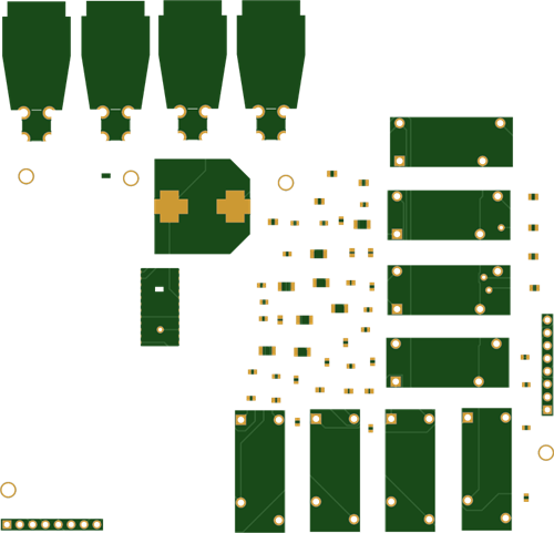
Test points |
x 5 | |
|
|
Yellow Connector jack |
x 1 | |
|
|
Red Connector Jack |
x 1 | |
|
|
Black Connector jack |
x 1 | |
|
|
Header 5x2 |
x 1 | |
|
|
Res 2.4k |
x 8 | |
|
|
Relay |
x 8 | |
|
|
Res 0 |
x 8 | |
|
|
Head screw |
x 4 | |
|
|
Header 8x1 |
x 2 | |
|
|
TLC6A598MDWR |
x 1 | |
|
|
Res 10k |
x 17 | |
|
|
Cap 220uF |
x 1 | |
|
|
Green LED |
x 8 | |
|
|
Cap 0.1uF |
x 10 |

|
Altium DesignerAltium Designer
|
|
|
|
Inventhub |
For Avionic Applications: Reliable Phase-Shift Driver PCB based on TLC6A598
Phase Shift:
Avionics refers to the electronic systems designed for use in aviation. It is a combination of both aircraft and electronic systems. It includes navigation, flight control, engine control system, fault or damage detection, and communication. Applications of avionics are in Commercial airliners, helicopters, military fighter jets, and spacecraft. They use avionics to provide services, track and identify performance measures, and operate within established safety parameters.
In avionics, communication through RADAR is very crucial. The TLC6A598 is responsible for communication and safety in avionics. They control the phase of elements in a phased array antenna in communication, especially in RADAR. This is how communication is possible in avionics.
TLC6A598:
It contains an 8-bit serial-in, parallel-out shift register that is used to provide an 8-bit D-type storage register. This device has built-in voltage clamps on the output side for inductive transient protection, so it can also drive relays, solenoids, and other low-current or high-voltage loads. They can limit the current level to avoid any short circuits in the device. This device is highly reliable and robust for avionic applications.
Outputs are low-side, open-drain DMOS transistors with output ratings of 50 V and 350-mA continuous sink-current capabilities. The current limit decreases as the junction temperature increases for additional device protection. A built-in load open or load short diagnostic mechanism provides enhanced safety protection. The device provides a cycle redundancy check to verify register values in the shift registers.
Board Design:
I have designed a board using a TLC6A598. The purpose of designing this board is to provide an example of the solution of controlling 8 channel relays. This board helps users evaluate the operation and performance of the TLC6A598. It operates with two power supplies i.e. 5V DC and 24V DC. One of them is used to control TLC6A598 and the other one is used to provide power to relays.

Design files:
I have uploaded the schematic file of this board online on Inventhub. The viewers can visually view and download it to implement my design.
For a better view of my PCB design board in different layers, I have uploaded the PCB file of my deign on Inventhub. The manufacturer can easily download this file and implement my design on a board without any error.
For fabrication of this board, I have created a release file of the project which is a ZIP file containing all schematic, PCB, routing layers, and 3D model of the chip. To fabricate my PCB, I will send this release file to my manufacturer instead of visiting him, he can download the file and fabricate my board.
Bill of Materials:
I also have created an online Bill of Material on Inventhub. Sometimes, it becomes difficult to order the component with the same footprint and dimensions as per design requirements. This BOM file contains the details of the dimensions of each component. The component provider can export the file in CSV format and can deliver my components easily. I can calculate the total cost of my project according to the components and manufacturer I have chosen for my design. By clicking on ‘Edit BOM’ I can select the ‘supply chain’ button to calculate the cost of my product.
Why TLC6A598?
As compared to NPIC6C596 and STPIC6D595 devices, TLC6A598 is more efficient and reliable. It protects the loads from any damage. They can work on high power and can limit the current. Following are the major reasons why TLC6A598 is better and preferable to other devices.
- Overcurrent Protection
- Low Power consumption
- Output Detection
- Serial Communication Error detection
- Thermal Shutdown
- Enhanced cascading for multiple stages
- Open and short load detection
Circuit Design and Testing:
The TLC6A598 device is designed to operate with an input voltage supply range from 3 V to 5.5 V. It operates with two supply power rails, one power rail for the TLC6A598 and another power rail for the relays. This board is designed to work with the USB2ANY board and USB2ANY Explore Software.
The USB2ANY board is available here.
The test setup of this board can be arranged as:

TLC6A598EVM Test Bench Setup by Texas Instruments
Resources:
For Avionic Applications: Reliable Phase-Shift Driver PCB based on TLC6A598
*PCBWay community is a sharing platform. We are not responsible for any design issues and parameter issues (board thickness, surface finish, etc.) you choose.


- Comments(0)
- Likes(0)
More by Arshmah Arshmah Shahkar
-
 Control Household Appliances Remotely- PCB Board
This is a simple remote controller circuit consisting of two main parts:TransmitterReceiverThese kin...
Control Household Appliances Remotely- PCB Board
This is a simple remote controller circuit consisting of two main parts:TransmitterReceiverThese kin...
-
 Better Quality of Sound with Class D Audio Amplifier PCB Board
What is Class D Amplifier?As the name suggests D, is a digital amplifier. It is also known as a swit...
Better Quality of Sound with Class D Audio Amplifier PCB Board
What is Class D Amplifier?As the name suggests D, is a digital amplifier. It is also known as a swit...
-
 Digital Voltmeter PCB Board To Measure Voltages Accurately
Digital Voltmeter:Digital voltmeters are used to measure potentials between two different points and...
Digital Voltmeter PCB Board To Measure Voltages Accurately
Digital Voltmeter:Digital voltmeters are used to measure potentials between two different points and...
-
 Control Direction of DC Motor Using H-Bridge Driver PCB
Working of H-Bridge Driver:H- Bridge driver circuit is made up of four transistors that act as switc...
Control Direction of DC Motor Using H-Bridge Driver PCB
Working of H-Bridge Driver:H- Bridge driver circuit is made up of four transistors that act as switc...
-
 FPGA PCB Using ICE40 To Drive 64×64 LED Matrix
ICE40 FPGA:The ICE40 chip is an ultra-low-power FPGA and sensor manager designed for ultra-low power...
FPGA PCB Using ICE40 To Drive 64×64 LED Matrix
ICE40 FPGA:The ICE40 chip is an ultra-low-power FPGA and sensor manager designed for ultra-low power...
-
 Heart Rate Monitoring PCB Board Design for Workout
The heart rate monitor is used to measure heartbeats in a minute. It can be useful in many applicati...
Heart Rate Monitoring PCB Board Design for Workout
The heart rate monitor is used to measure heartbeats in a minute. It can be useful in many applicati...
-
 Determine Electric Field Strength To Adjust Gain and Transmitting Range-PCB Design
Description:This PCB design board is useful for the RF signals to determine the strength of the sign...
Determine Electric Field Strength To Adjust Gain and Transmitting Range-PCB Design
Description:This PCB design board is useful for the RF signals to determine the strength of the sign...
-
 H-Bridge Inverter PCB Design Board
The H bridge inverter is used to convert DC voltages to AC voltages. An h bridge is common in genera...
H-Bridge Inverter PCB Design Board
The H bridge inverter is used to convert DC voltages to AC voltages. An h bridge is common in genera...
-
 For Avionic Applications: Reliable Phase-Shift Driver PCB based on TLC6A598
Phase Shift:Avionics refers to the electronic systems designed for use in aviation. It is a combinat...
For Avionic Applications: Reliable Phase-Shift Driver PCB based on TLC6A598
Phase Shift:Avionics refers to the electronic systems designed for use in aviation. It is a combinat...
-
 Water Level Indicator PCB Design Board
Measure level of Water:The water level indicator is used to indicate the level of water or any fluid...
Water Level Indicator PCB Design Board
Measure level of Water:The water level indicator is used to indicate the level of water or any fluid...
-
 Fire Alarm Sensor with Arduino Interface PCB Design Board
Flame sensor:A flame sensor is sensitive to normal light. It is used to detect the presence of flame...
Fire Alarm Sensor with Arduino Interface PCB Design Board
Flame sensor:A flame sensor is sensitive to normal light. It is used to detect the presence of flame...
-
 Getting Started with STM32- Arduino code Programming and PCB Design
STM32 Board:STM32 is a high-performance, development board with loads of features in a small form fa...
Getting Started with STM32- Arduino code Programming and PCB Design
STM32 Board:STM32 is a high-performance, development board with loads of features in a small form fa...
-
 PCB Board To Determine the Performance and Properties of an Antenna
Antenna in Wireless Communication:Antennas are everywhere! An Antenna is an electrical device that c...
PCB Board To Determine the Performance and Properties of an Antenna
Antenna in Wireless Communication:Antennas are everywhere! An Antenna is an electrical device that c...
-
 PCB Device to Test Continuity in Circuit and Polarity of Components
Introduction:A continuity testing device is used to check the breakage and shortage of wires in a ci...
PCB Device to Test Continuity in Circuit and Polarity of Components
Introduction:A continuity testing device is used to check the breakage and shortage of wires in a ci...
-
 High Accuracy and Low Power Digital Temperature Sensor PCB MAX30207
Introduction to MAX30207:MAX30207 IC is a low-power and high-accuracy digital temperature sensor. It...
High Accuracy and Low Power Digital Temperature Sensor PCB MAX30207
Introduction to MAX30207:MAX30207 IC is a low-power and high-accuracy digital temperature sensor. It...
-
 PICAXE40X2 Efficient MCU Ideal in Hobbyist Project PCB
Overview:Take an example of a microwave oven, the microcontroller processes your input that you ente...
PICAXE40X2 Efficient MCU Ideal in Hobbyist Project PCB
Overview:Take an example of a microwave oven, the microcontroller processes your input that you ente...
-
 DC to AC Inverter Based on CD4047: PCB Design Board
Inverter:Inverters are those electrical devices that convert DC voltages to AC voltages. It is used ...
DC to AC Inverter Based on CD4047: PCB Design Board
Inverter:Inverters are those electrical devices that convert DC voltages to AC voltages. It is used ...
-
 SMPS Power Supply PCB Board Design for Different Applications
Background Story:Switch Mode Power Supply (SMPS) can switch the main AC supply to a 12V DC supply fo...
SMPS Power Supply PCB Board Design for Different Applications
Background Story:Switch Mode Power Supply (SMPS) can switch the main AC supply to a 12V DC supply fo...
-
-
-
-
Tester for Touch Screen Digitizer without using microcontroller
334 2 2 -
Audio reactive glow LED wristband/bracelet with NFC / RFID-Tags
317 0 1 -
-
-


