


|
|
Si4825 Radio chip |
x 1 | |
|
|
1x3 Switch |
x 1 | |
|
|
Ferrite core coil |
x 1 | |
|
|
Microammeter |
x 1 | |
|
|
potentiometer 2x100k |
x 1 | |
|
|
potentiometer 10k |
x 1 | |
|
|
Audio amplifier board PAM8403 |
x 1 | |
|
|
Speaker: 0.25W, 8 ohms |
x 1 | |
|
|
resistors and capacitors |
x 1 | |
|
|
32.768 kHz Crystal |
x 1 |

|
Soldering iron (generic) |
|

|
Solder Wire, Lead Free |
DIY Si4825 A10 multiband Radio (MW,SW,FM)
Thanks to the production of specialized radio chips, nowadays it is possible to make a quality multiband receiver by ourselves in a very simple way. In several of my previous videos, I described ways to make such radio receivers using microcontrollers. The receiver described in this project is very simple and consists of only one specialized chip, no programming is required, no tuning is required and the receiver works great immediately after connecting the components.
The receiver is made according to the demo schematic diagram found in the manufactirer datasheet. The heart of the receiver is the Si4825 A10 IC, which is extremely cheap, and we can get a five-piece lot for a total price of less than two dollars.

Despite the low price, it has excellent features and completely covers the three areas of MW, SW, and FM bands.
The device is relatively simple to make and consists of several components.
- Si4825 A10 IC
- a ferrite core coil removed from a defective portable MW radio (optional)
- A microammeter that is actually part of an old analog multimeter
- Stereo potentiometer 2x100k
- Potentiometer 10K
- Small Audio amplifier board PAM8403
- Band switch (2x3 positions)
- several resistors and capacitors
- and a small speaker
On the back of the receiver there are BNC connectors for AM and FM antenna. A crystal with a frequency of 32,768 Megahertz is mounted on the chip itself.

This project is sponsored by PCBWay. This year, PCBWay organizes the Seventh Project Design Contest where, in addition to Electronic and Mechanical Project, also has been added a new category: STM32 Project. For the best selected projects are provided rich prizes in cash, coupons and special gifts. Submit your project for participation in this Contest from 2nd, Sep, 2024 to 19th, Jan, 2025. For more details and instructions visit the given page. Let PCBway always be your first choice.

Band selection is done with a switch that actually forms a voltage divider, and the given resistances cover the following frequency ranges:

AM from 510 to 1710 KHz
SW from 5.9 MHz to 18 MHz
and FM from 87 to 108 MHz
The frequency is selected using a two potentiometers in a way that changes the voltage between the Tune1 and Tune2 pins.

100k potentiometer is for coarse tuning and 10k for fine tuning. The other channel of the 100K stereo potentiometer is connected through a series-connected trimmer potentiometer of 10K to the microammeter that serves as an analog radio scale. The method of connection is presented in the diagram, whereby we adjust the trimmer potentiometer to enable a full deflection of the arrow when the tuning potentiometer is in the extreme right position.

I still have to mark the scale with appropriate bands and frequencies, but even this way there is enough visibility. The audio output of the Si4825 is connected to the input of a small audio amplifier to which a suitable speaker is connected. On both sides of the instrument I placed warm white LEDs for better readability of the scale. It is important to mention that 5V is connected to the input of the radio, and the Si4825 chip should be powered with a maximum of 3.3V.

For this purpose I used the simplest way to reduce the voltage using three series connected silicon diodes, as shown in the picture.
And now let's see how the device works in real conditions: First we need to connect a suitable antenna, and then immediately after switching on, the scale takes the given position which depends on the resistance of the scanning potentiometer. Analogous to the rotation of the potentiometer, the needle of the instrument is also moved. Then we select the desired band, set the audio volume, and we can start dialing stations. I should also mention that the ideal option for tuning the stations would be a multi-turn potentiometer.

I started the project with a multiturn potentiometer, but later found that it was defective, so I looked for another solution with two potentiometers for coarse and fine tunning.
And finally, a short conclusion. I started making radio receivers in the previous century with transistors, when making and especially setting up a quality radio receiver required very expensive equipment and vast knowledge in the field of electronics and radio technology. Nowadays, with the development of specialized chips, the self-production of quality radio receivers is extremely simplified, there is no need for any adjustments, and the total price is also very low. However, I personally still prefer making radio receivers with discrete elements, and even vacuum tubes, where we can learn a lot from this area, and the satisfaction when setting up and making such a receiver is greater, and a well-made discrete receiver often has better selectivity and sensitivity than that with specialized ICs. The radio is installed in a suitable box made of PVC material with a thickness of 3 and 5 mm and covered with colored self-adhesive wallpaper.


DIY Si4825 A10 multiband Radio (MW,SW,FM)


Raspberry Pi 5 7 Inch Touch Screen IPS 1024x600 HD LCD HDMI-compatible Display for RPI 4B 3B+ OPI 5 AIDA64 PC Secondary Screen(Without Speaker)
BUY NOW


- Comments(0)
- Likes(0)
More by Mirko Pavleski
-
 Arduino 3D Printed self Balancing Cube
Self-balancing devices are electronic devices that use sensors and motors to keep themselves balanc...
Arduino 3D Printed self Balancing Cube
Self-balancing devices are electronic devices that use sensors and motors to keep themselves balanc...
-
 DIY Avionics Simulator with ESP32 - Artificial Horizon, Compass & Altimeter
The inspiration for this project comes from classical aircraft cockpit instruments used for navigat...
DIY Avionics Simulator with ESP32 - Artificial Horizon, Compass & Altimeter
The inspiration for this project comes from classical aircraft cockpit instruments used for navigat...
-
 DIY Miniature X-Ray Machine using a TV Vacuum Tube DY86
An X-ray machine (or radiograph) is a quick, painless medical test that produces images of the struc...
DIY Miniature X-Ray Machine using a TV Vacuum Tube DY86
An X-ray machine (or radiograph) is a quick, painless medical test that produces images of the struc...
-
 Simple SDR Receiver Using 2x NE612 - Dual Conversion, Superheterodyne (0.1–30 MHz)
SDR (Software Defined Radio) is a radio system in which most of the functions of a classic radio (f...
Simple SDR Receiver Using 2x NE612 - Dual Conversion, Superheterodyne (0.1–30 MHz)
SDR (Software Defined Radio) is a radio system in which most of the functions of a classic radio (f...
-
 DIY Vintage TV VU Meter with peak indicators
Some time ago in one of my projects I presented you a way to turn a black and white old mini TV int...
DIY Vintage TV VU Meter with peak indicators
Some time ago in one of my projects I presented you a way to turn a black and white old mini TV int...
-
 DIY Tesla Coil based Plasma Rife Machine
In several of my previous videos, I presented you with different ways to make a Rife Machine, from ...
DIY Tesla Coil based Plasma Rife Machine
In several of my previous videos, I presented you with different ways to make a Rife Machine, from ...
-
 ESP32 Analog VU Meter – Smooth Needle, Real Audio Response (DIY Build)
In several of my previous videos I have shown you how to make analog VU meters emulated on differen...
ESP32 Analog VU Meter – Smooth Needle, Real Audio Response (DIY Build)
In several of my previous videos I have shown you how to make analog VU meters emulated on differen...
-
 The Ultimate Smartphone VFO ESP32 & Si5351 Wireless Control
Variable frequency oscillators (VFOs) are commonly used in radio transmitters and receivers, especi...
The Ultimate Smartphone VFO ESP32 & Si5351 Wireless Control
Variable frequency oscillators (VFOs) are commonly used in radio transmitters and receivers, especi...
-
 DIY Shortwave Propagation Monitor - Measure Ionosphere Conditions
Shortwave Propagation is the way radio waves in the 3 to 30 MHz range travel from point A to point ...
DIY Shortwave Propagation Monitor - Measure Ionosphere Conditions
Shortwave Propagation is the way radio waves in the 3 to 30 MHz range travel from point A to point ...
-
 Professional grade Smart Lock with ESP32, BLE and Android App Control
An electronic codelock is a security device that grants access using a numerical sequence—a PIN cod...
Professional grade Smart Lock with ESP32, BLE and Android App Control
An electronic codelock is a security device that grants access using a numerical sequence—a PIN cod...
-
 Building a 3-Input Stereo ECC83 (12AX7) Tube Preamp
Some time ago I presented you a project for a 3W stereo tube amplifier with a GU32 output vacuum t...
Building a 3-Input Stereo ECC83 (12AX7) Tube Preamp
Some time ago I presented you a project for a 3W stereo tube amplifier with a GU32 output vacuum t...
-
 ESP32 Weather Dashboard with Satellite Maps and 16-day Weather Forecast
As you can see from my previous videos, besides Electronics, my fields of experimentation and proje...
ESP32 Weather Dashboard with Satellite Maps and 16-day Weather Forecast
As you can see from my previous videos, besides Electronics, my fields of experimentation and proje...
-
 Retro Analog VU Meter on Round dispalys (ESP32 and GC9A01)
Recently, in one of my previous videos I presented you a Retro VU Meter project on round displays ...
Retro Analog VU Meter on Round dispalys (ESP32 and GC9A01)
Recently, in one of my previous videos I presented you a Retro VU Meter project on round displays ...
-
 Ultimate 2-Player Reaction Timer with WS2812B LED Strips & Arduino
Arcade reaction game is a genre of play designed to test a player's physical response time and hand...
Ultimate 2-Player Reaction Timer with WS2812B LED Strips & Arduino
Arcade reaction game is a genre of play designed to test a player's physical response time and hand...
-
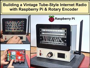 Building a Vintage Tube-Style Internet Radio with Raspberry Pi & Rotary Encoder
Internet radio (also known as web radio or net radio) is a digital audio service transmitted via th...
Building a Vintage Tube-Style Internet Radio with Raspberry Pi & Rotary Encoder
Internet radio (also known as web radio or net radio) is a digital audio service transmitted via th...
-
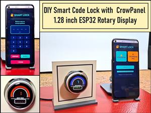 DIY Smart Code Lock with CrowPanel 1.28 ESP32 Rotary Display
A code lock is a keyless security device—either mechanical or electronic—that restricts access to d...
DIY Smart Code Lock with CrowPanel 1.28 ESP32 Rotary Display
A code lock is a keyless security device—either mechanical or electronic—that restricts access to d...
-
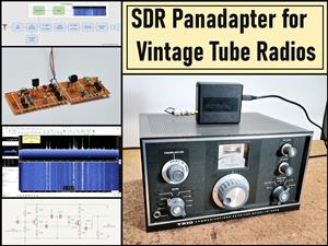 SDR Panadapter for Vintage Tube Radios – Step-by-Step Tutorial
A radio panadapter (or panoramic adapter) is a device or software tool used in amateur radio and ot...
SDR Panadapter for Vintage Tube Radios – Step-by-Step Tutorial
A radio panadapter (or panoramic adapter) is a device or software tool used in amateur radio and ot...
-
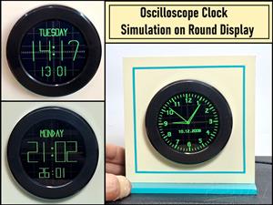 Oscilloscope Clock Simulation on a Round ESP32 Display
An oscilloscope clock is a circuit that turns an old analog oscilloscope into a stylish, retro-them...
Oscilloscope Clock Simulation on a Round ESP32 Display
An oscilloscope clock is a circuit that turns an old analog oscilloscope into a stylish, retro-them...
-
Programmable Mist Maker - XIAO / QT PY Extension
440 0 0 -
RadioHAT - Raspberry Pi radio development platform
342 0 1 -
-
-
-
-
ARPS-2 – Arduino-Compatible Robot Project Shield for Arduino UNO
2894 0 6 -
A Compact Charging Breakout Board For Waveshare ESP32-C3
3394 3 8 -
AI-driven LoRa & LLM-enabled Kiosk & Food Delivery System
3721 2 2


