


Clap Switch With PICO 2 and MAX9814
The idea here was to create a simple breadboard setup for testing with the MAX9814 microphone module and PICO. Setting up this breadboard version was critical in developing a Clap Switch Circuit, which will be developed soon.
In this article, we will explore the MAX9814 microphone sensor's setup guide and the preparation of a basic clap switch with it, utilizing an OLED screen and the PICO 2.
MAX9814
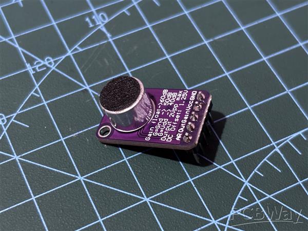
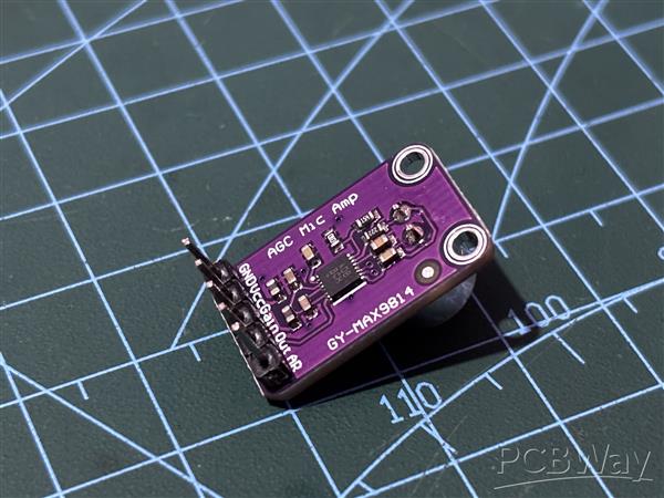
The MAX9814 is a high-performance microphone amplifier module designed for applications requiring precise audio capture and amplification. It features Automatic Gain Control (AGC), which dynamically adjusts the amplification level to accommodate varying audio input levels, ensuring consistent and high-quality output.
We use MAX9814 in our Clap Switch project because of the AGC, which dynamically adjusts the gain to ensure consistent audio output, even in varying noise environments. This means it can accurately detect claps regardless of background noise levels. Additionally, its low input-referred noise density and low Total Harmonic Distortion (THD) ensure that the audio signal is clear and precise, making the detection of clap sounds more reliable.
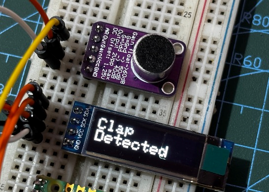
It operates on 2.7V to 5.5V, consumes around 3mA, and offers a 2V peak-to-peak output on a 1.25V DC bias, covering a frequency range from 20Hz to 20kHz. With a low input-referred noise density of 30 nV/√Hz and a THD of 0.04%, it ensures clear, high-fidelity audio. The amplifier supports programmable gain settings of 40dB, 50dB, and 60dB, provides a 2V microphone bias, and works in temperatures from -40°C to +85°C, packaged in a compact 14-pin TDFN.
PCBWAY GIFTSHOP
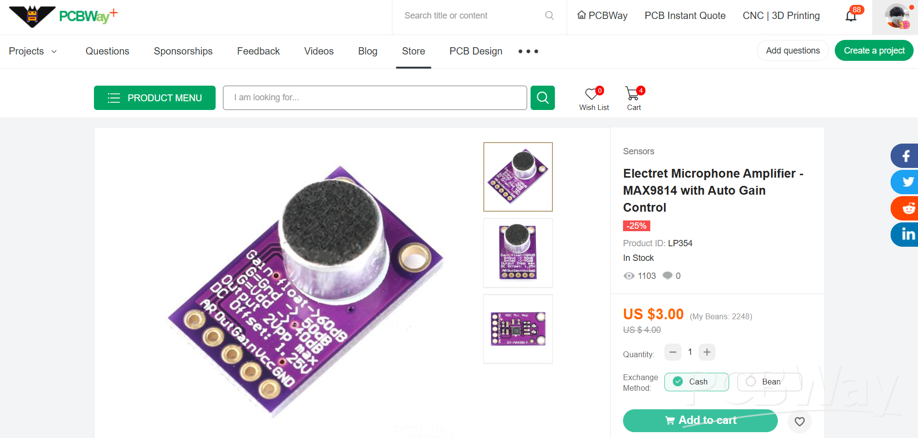
As for sourcing the MAX9814 Microphone Amplifier module along with PICO 2 we used in this project, we got them from PCBWAY's Giftshop.
https://www.pcbway.com/project/gifts_detail/Raspberry_Pi_Pico_2_a84bd81f.html
PCBWAY gift shop is an online marketplace where you can get a variety of electronics modules and boards for their genuine price, or you could use the PCBWAY currency, which is called beans.
You get beans after ordering something from PCBWAY as reward points, or you can also get them by posting any project in the PCBWAY community.
Also, PCBWay is hosting its 7th Project Design Contest, a global competition that invites electronics enthusiasts, engineers, and makers to showcase their innovative projects. The contest provides a platform for participants to share their creativity and technical expertise with the broader community.
This year’s competition includes three major categories: electronic project, mechanical project and SMT 32 project
With prizes awarded for the most exceptional designs, the contest aims to inspire and support innovation, making it an exciting opportunity for both professionals and hobbyists to gain recognition and connect with like-minded creators.
You guys can check out PCBWAY if you want great PCB service at an affordable rate.
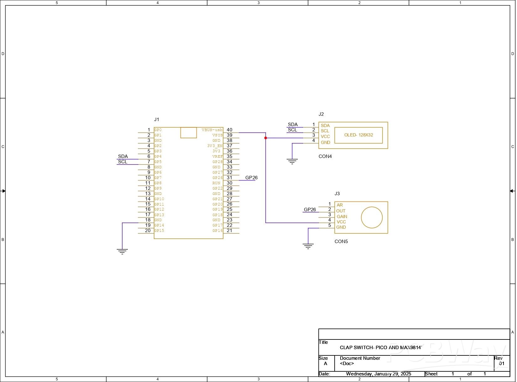
PICO and MAX9814 Wiring
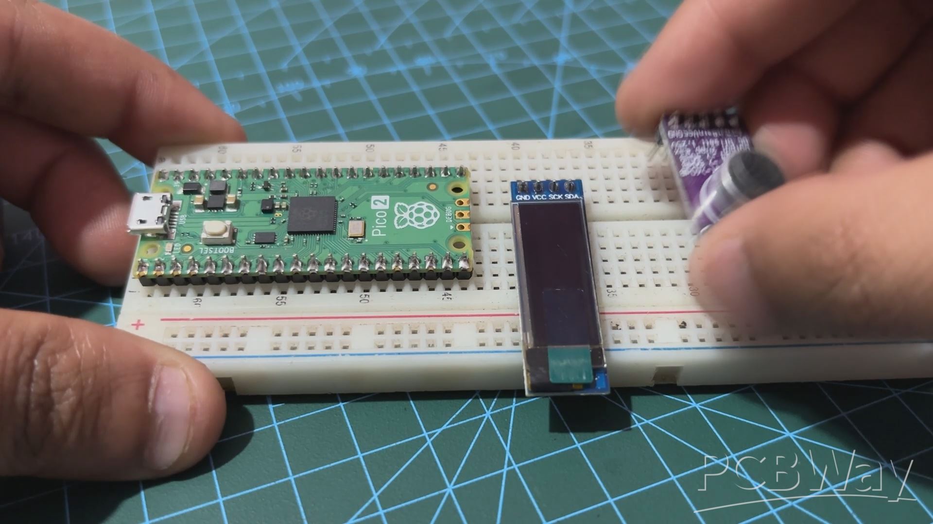
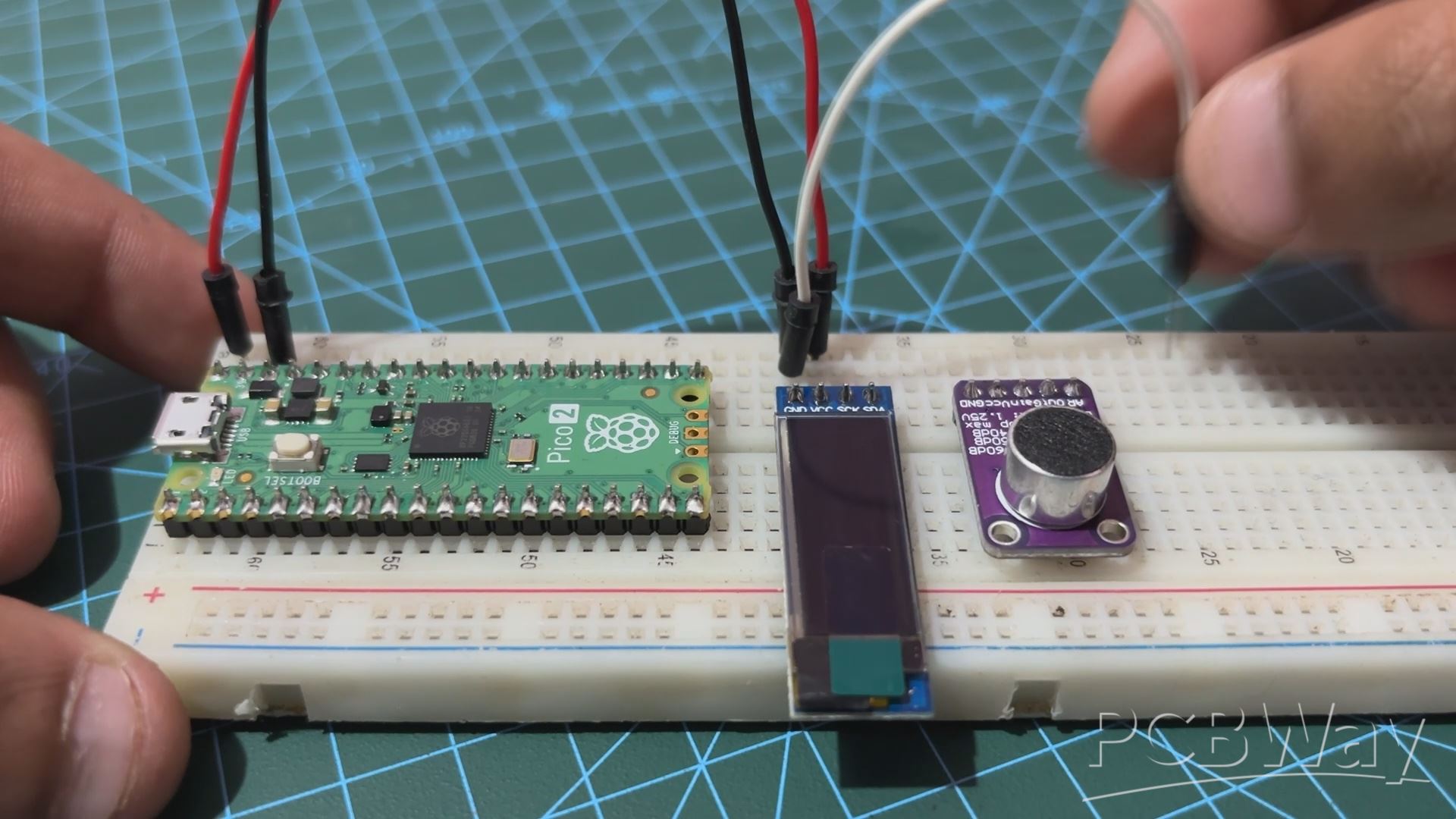
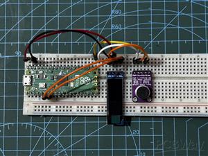
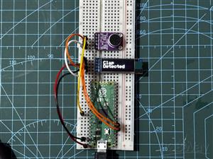
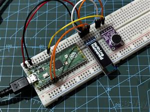
- We start the assembly process by placing all three components, which are the PICO 2, the SSD1306 OLED screen and the MAX9814 MIC Module, on the breadboard.
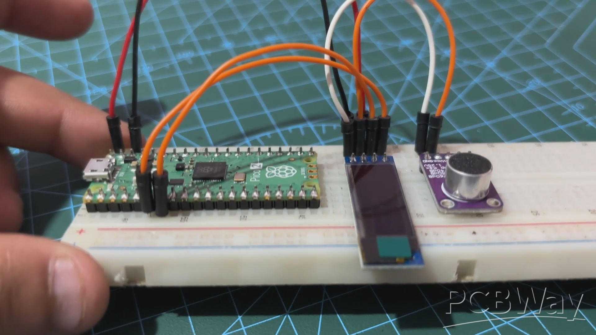
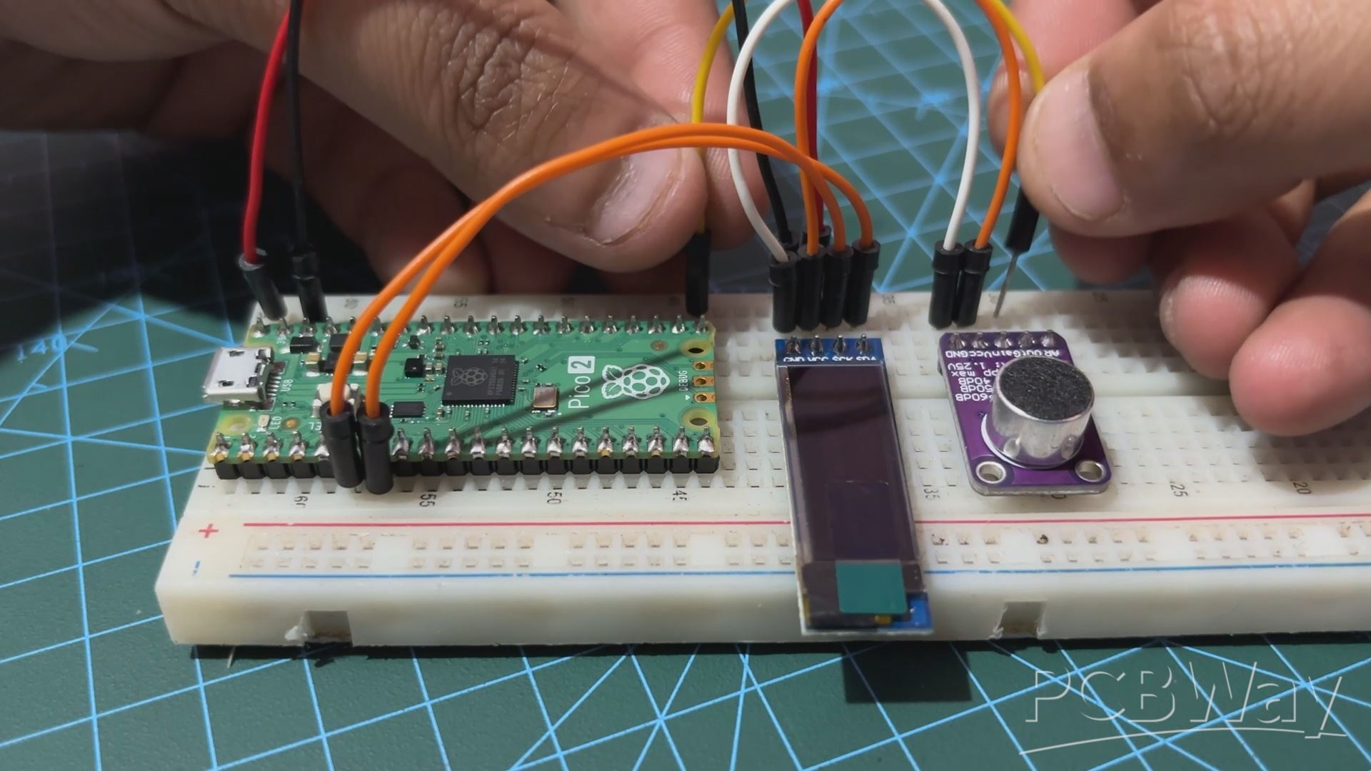
- Next, we first connected the VBUS of PICO 2 with the OLED's VCC and MAX Module's VCC, all three in parallel. GND of all three are also connected in parallel.
- We now connect the SDA and SCL of OLED with the GPIO4 and GPIO5 of the PICO.
- At last we connected the OUT pin of the MAX9814 module with GPIO26 of the PICO 2.
The wiring process has been completed.
CODE
We next uploaded the below sketch into the PICO 2.
#define SCREEN_WIDTH 128 // OLED display width, in pixels
#define SCREEN_HEIGHT 32 // OLED display height, in pixels
#define OLED_RESET    -1 // Reset pin # (or -1 if sharing Arduino reset pin)
#define OLED_ADDRESS 0x3C // I2C address for the SSD1306 OLED display
Adafruit_SSD1306 display(SCREEN_WIDTH, SCREEN_HEIGHT, &Wire, OLED_RESET);

#define MIC_PIN 26
#define CLAP_THRESHOLD 500 // Adjust based on your sensor's range
#define CLAP_DELAY 200 // Minimum delay between claps in milliseconds
#define CLAP_WINDOW 1000 // Time window for detecting second clap in milliseconds
#define DISPLAY_DURATION 5000 // Time to display "Clap Detected" message

unsigned long last_clap_time = 0;
unsigned long message_display_time = 0;
bool display_clap_message = false;

void setup() {
  // Initialize the serial communication for debugging
  Serial.begin(9600);

  // Initialize the OLED display
  if (!display.begin(SSD1306_SWITCHCAPVCC, OLED_ADDRESS)) {
    Serial.println(F("SSD1306 allocation failed"));
    for (;;);
  }
  display.clearDisplay();
  display.setTextSize(2);
  display.setTextColor(SSD1306_WHITE);
  display.setCursor(0, 0);
  display.display();
}

void loop() {
  int analog_val = analogRead(MIC_PIN); // Read microphone value
  unsigned long current_time = millis();

  // Debugging information
  Serial.print("Analog Value: ");
  Serial.println(analog_val);

  // Detect clap
  if (analog_val > CLAP_THRESHOLD) {
    if (current_time - last_clap_time > CLAP_DELAY) {
      Serial.println("Clap detected");
      display_clap_message = true;
      message_display_time = current_time;
      last_clap_time = current_time;
    }
  }

  // Update the OLED display
  display.clearDisplay();

  if (display_clap_message) {
    display.setCursor(0, 0);
    display.println("Clap");
    display.setCursor(0, 16); // Move to the second line
    display.println("Detected");
    if (current_time - message_display_time > DISPLAY_DURATION) {
      display_clap_message = false;
    }
  } else {
    display.setCursor(0, 0);
    display.println("Nothing");
    display.setCursor(0, 16); // Move to the second line
    display.println("happened");
  }

  display.display();

  // Short delay for stability
  delay(100);
}
Our Code Set up the OLED display and a microphone to detect claps and display corresponding messages.
The OLED is initialized with specific dimensions and an I2C address, and the microphone is connected to pin 26, with a clap detection threshold set at 500. When the microphone detects a sound above this threshold, it registers a clap, considering a minimum delay between claps and a defined window for detecting the second clap.
If a clap is detected, the OLED displays "Clap Detected" for five seconds; otherwise, it displays "Nothing happened." The code includes serial output for debugging, allowing for monitoring of analog values and confirming clap detection. This setup ensures effective and reliable clap detection with the appropriate message displayed on the OLED screen.
Make sure to install the OLED Library before using this sketch-
https://github.com/adafruit/Adafruit_SSD1306
Result
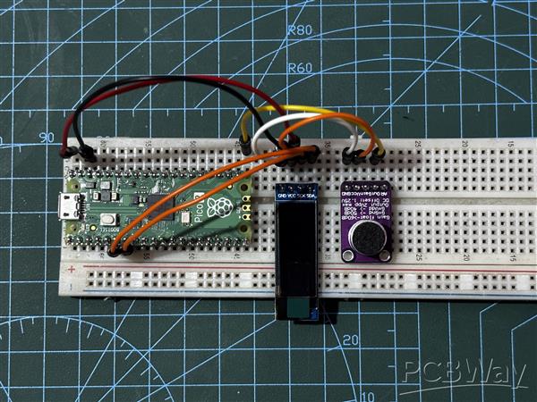
This is the end result of this straightforward but crucial build: a CLAP SENSOR configuration that uses the MAX9814 microphone module alongside with the PICO 2 and an OLED screen for displaying output. In order to turn on or off AC appliances—a room light with a clap—we will be developing a real CLAP switch, thus this setup is crucial.
Setting up the breadboard version of the project was crucial and informative because it helped us understand exactly how to prepare it.
Overall, this project was a success, and i will be back with the CLAP Switch project shortly.
In addition, we appreciate PCBWAY's support of this project. Visit them for a variety of PCB-related services, such as stencil and PCB assembly services, as well as 3D printing services.
Thanks for reaching this far. Peace
#define SCREEN_WIDTH 128 // OLED display width, in pixels
#define SCREEN_HEIGHT 32 // OLED display height, in pixels
#define OLED_RESET -1 // Reset pin # (or -1 if sharing Arduino reset pin)
#define OLED_ADDRESS 0x3C // I2C address for the SSD1306 OLED display
Adafruit_SSD1306 display(SCREEN_WIDTH, SCREEN_HEIGHT, &Wire, OLED_RESET);
#define MIC_PIN 26
#define CLAP_THRESHOLD 500 // Adjust based on your sensor's range
#define CLAP_DELAY 200 // Minimum delay between claps in milliseconds
#define CLAP_WINDOW 1000 // Time window for detecting second clap in milliseconds
#define DISPLAY_DURATION 5000 // Time to display "Clap Detected" message
unsigned long last_clap_time = 0;
unsigned long message_display_time = 0;
bool display_clap_message = false;
void setup() {
// Initialize the serial communication for debugging
Serial.begin(9600);
// Initialize the OLED display
if (!display.begin(SSD1306_SWITCHCAPVCC, OLED_ADDRESS)) {
Serial.println(F("SSD1306 allocation failed"));
for (;;);
}
display.clearDisplay();
display.setTextSize(2);
display.setTextColor(SSD1306_WHITE);
display.setCursor(0, 0);
display.display();
}
void loop() {
int analog_val = analogRead(MIC_PIN); // Read microphone value
unsigned long current_time = millis();
// Debugging information
Serial.print("Analog Value: ");
Serial.println(analog_val);
// Detect clap
if (analog_val > CLAP_THRESHOLD) {
if (current_time - last_clap_time > CLAP_DELAY) {
Serial.println("Clap detected");
display_clap_message = true;
message_display_time = current_time;
last_clap_time = current_time;
}
}
// Update the OLED display
display.clearDisplay();
if (display_clap_message) {
display.setCursor(0, 0);
display.println("Clap");
display.setCursor(0, 16); // Move to the second line
display.println("Detected");
if (current_time - message_display_time > DISPLAY_DURATION) {
display_clap_message = false;
}
} else {
display.setCursor(0, 0);
display.println("Nothing");
display.setCursor(0, 16); // Move to the second line
display.println("happened");
}
display.display();
// Short delay for stability
delay(100);
}
Clap Switch With PICO 2 and MAX9814


Raspberry Pi 5 7 Inch Touch Screen IPS 1024x600 HD LCD HDMI-compatible Display for RPI 4B 3B+ OPI 5 AIDA64 PC Secondary Screen(Without Speaker)
BUY NOW


- Comments(0)
- Likes(0)
More by Arnov Arnov sharma
-
 DIY XBOX Controller
Greetings everyone, and welcome back. Here's something fun and custom.This is my version of an Xbox ...
DIY XBOX Controller
Greetings everyone, and welcome back. Here's something fun and custom.This is my version of an Xbox ...
-
 Pocket SNES
Greetings everyone, and welcome back! Today, I’ve got something fun and tiny to share—the Pocket SNE...
Pocket SNES
Greetings everyone, and welcome back! Today, I’ve got something fun and tiny to share—the Pocket SNE...
-
 Batocera Arcade Box
Greetings everyone and welcome back, Here's something. Fun and nostalgic. Right now, we are using ou...
Batocera Arcade Box
Greetings everyone and welcome back, Here's something. Fun and nostalgic. Right now, we are using ou...
-
 64x32 Matrix Panel Setup with PICO 2
Greetings everyone and welcome back.So here's something fun and useful: a Raspberry Pi Pico 2-powere...
64x32 Matrix Panel Setup with PICO 2
Greetings everyone and welcome back.So here's something fun and useful: a Raspberry Pi Pico 2-powere...
-
 Portable Air Quality Meter
Hello everyone, and welcome back! Today, I have something incredibly useful for you—a Portable Air Q...
Portable Air Quality Meter
Hello everyone, and welcome back! Today, I have something incredibly useful for you—a Portable Air Q...
-
 WALKPi PCB Version
Greetings everyone and welcome back, This is the WalkPi, a homebrew audio player that plays music fr...
WALKPi PCB Version
Greetings everyone and welcome back, This is the WalkPi, a homebrew audio player that plays music fr...
-
 Delete Button XL
Greetings everyone and welcome back, and here's something fun and useful.In essence, the Delete Butt...
Delete Button XL
Greetings everyone and welcome back, and here's something fun and useful.In essence, the Delete Butt...
-
 Arduino Retro Game Controller
Greetings everyone and welcome back. Here's something fun.The Arduino Retro Game Controller was buil...
Arduino Retro Game Controller
Greetings everyone and welcome back. Here's something fun.The Arduino Retro Game Controller was buil...
-
 Super Power Buck Converter
Greetings everyone and welcome back!Here's something powerful, The SUPER POWER BUCK CONVERTER BOARD ...
Super Power Buck Converter
Greetings everyone and welcome back!Here's something powerful, The SUPER POWER BUCK CONVERTER BOARD ...
-
 Pocket Temp Meter
Greetings and welcome back.So here's something portable and useful: the Pocket TEMP Meter project.As...
Pocket Temp Meter
Greetings and welcome back.So here's something portable and useful: the Pocket TEMP Meter project.As...
-
 Pico Powered DC Fan Driver
Hello everyone and welcome back.So here's something cool: a 5V to 12V DC motor driver based around a...
Pico Powered DC Fan Driver
Hello everyone and welcome back.So here's something cool: a 5V to 12V DC motor driver based around a...
-
 Mini Solar Light Project with a Twist
Greetings.This is the Cube Light, a Small and compact cube-shaped emergency solar light that boasts ...
Mini Solar Light Project with a Twist
Greetings.This is the Cube Light, a Small and compact cube-shaped emergency solar light that boasts ...
-
 PALPi V5 Handheld Retro Game Console
Hey, Guys what's up?So this is PALPi which is a Raspberry Pi Zero W Based Handheld Retro Game Consol...
PALPi V5 Handheld Retro Game Console
Hey, Guys what's up?So this is PALPi which is a Raspberry Pi Zero W Based Handheld Retro Game Consol...
-
 DIY Thermometer with TTGO T Display and DS18B20
Greetings.So this is the DIY Thermometer made entirely from scratch using a TTGO T display board and...
DIY Thermometer with TTGO T Display and DS18B20
Greetings.So this is the DIY Thermometer made entirely from scratch using a TTGO T display board and...
-
 Motion Trigger Circuit with and without Microcontroller
GreetingsHere's a tutorial on how to use an HC-SR505 PIR Module with and without a microcontroller t...
Motion Trigger Circuit with and without Microcontroller
GreetingsHere's a tutorial on how to use an HC-SR505 PIR Module with and without a microcontroller t...
-
 Motor Driver Board Atmega328PU and HC01
Hey, what's up folks here's something super cool and useful if you're making a basic Robot Setup, A ...
Motor Driver Board Atmega328PU and HC01
Hey, what's up folks here's something super cool and useful if you're making a basic Robot Setup, A ...
-
 Power Block
Hey Everyone what's up!So this is Power block, a DIY UPS that can be used to power a bunch of 5V Ope...
Power Block
Hey Everyone what's up!So this is Power block, a DIY UPS that can be used to power a bunch of 5V Ope...
-
 Goku PCB Badge V2
Hey everyone what's up!So here's something SUPER cool, A PCB Board themed after Goku from Dragon Bal...
Goku PCB Badge V2
Hey everyone what's up!So here's something SUPER cool, A PCB Board themed after Goku from Dragon Bal...
-
Programmable Mist Maker - XIAO / QT PY Extension
1054 2 1 -
RadioHAT - Raspberry Pi radio development platform
850 0 2 -
-
-
-
-
ARPS-2 – Arduino-Compatible Robot Project Shield for Arduino UNO
3316 0 6 -
A Compact Charging Breakout Board For Waveshare ESP32-C3
3921 3 8 -
AI-driven LoRa & LLM-enabled Kiosk & Food Delivery System
4309 2 2


